2006 March (529kB) - Pacific Soaring Council
2006 March (529kB) - Pacific Soaring Council
2006 March (529kB) - Pacific Soaring Council

Create successful ePaper yourself
Turn your PDF publications into a flip-book with our unique Google optimized e-Paper software.
through the foot plate (already glasses in) required<br />
the use of coat hanger wire and plenty of tape to<br />
hour and to 1.5second duration maximum. I Hope<br />
this helps with your installation, and good luck!<br />
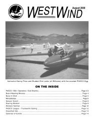
Parcel shelf hard mounts before reinforcement<br />
The unit prior to painting showing tapped base<br />
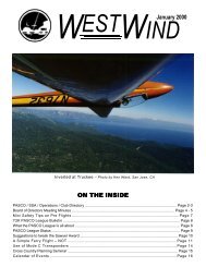
Assembled unit with antenna and bracket<br />
attach the connector to the hanger wire and use this<br />
to feed the cable through the extraordinarily small<br />
and awkward space near the rudder pedals so the<br />
cable could be run up the panel and canopy support<br />
arm in the nose up the instrument panel itself. RJ11<br />
connectors are small and brittle and so need plenty<br />
of tape to protect them when being pulled through<br />
an awkward confined space. Making space for the<br />
coax cable to go underneath the antenna and plate<br />
and up into the ELT itself required some spacers<br />
attached to the base plate to raise the plate enough<br />
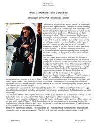
(see Fig 7-8) Drilling through the gear box for the<br />
cable was not an option as there was no clearance<br />
from the box to the gear and the risk of fouling the<br />
gear mechanism itself was too high. I key part of<br />
the installation is the use of an elbow adaptor for<br />
the antenna BNC cable – without this the unit would<br />
never have fit in the space available.<br />
Cramped space for the cable into the nose<br />
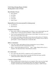
Finally, the installed unit is shown.. Test the unit<br />
before your final installation by monitoring 121.5<br />
while turning on briefly. Transmitter tests on the<br />
ground are restricted to the first 5 minutes of each<br />
11