RG-RELAYS - Panasonic Electric Works CZ
RG-RELAYS - Panasonic Electric Works CZ
RG-RELAYS - Panasonic Electric Works CZ

You also want an ePaper? Increase the reach of your titles
YUMPU automatically turns print PDFs into web optimized ePapers that Google loves.
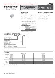
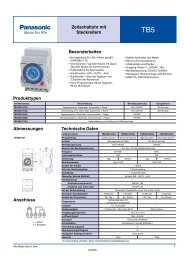
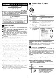
HIGH FREQUENCY<br />
<strong>RG</strong> <strong>RELAYS</strong> WITH 1C<br />
AND 2C CONTACTS<br />
<strong>RG</strong>-<strong>RELAYS</strong><br />
25<br />
.984<br />
19<br />
.748<br />
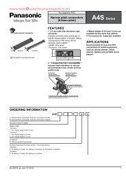
1 Form C<br />
10.4<br />
.409<br />
25<br />
.984<br />
23<br />
.906<br />
9.9<br />
.390<br />
• Excellent high frequency characteristics<br />
Isolation: Min. 65dB (at 900 MHz)<br />
Insertion loss: Max. 1.0 (at 900 MHz)<br />
• Wide selection<br />
Characteristic impedance: 50 Ω type and 75 Ω type<br />
Coil: Single side stable and latching type<br />
• 1 A 24 V DC switching capacity<br />
• Sealed construction for automatic cleaning<br />
• High sensitivity 350W (1 Form C) in small size<br />
SPECIFICATIONS<br />
Contact<br />
Arrangement<br />
Contact material<br />
Initial contact resistance, max.<br />
(By voltage drop 6 V DC 1 A)<br />
Max. switching power<br />
Max. switching voltage<br />
Max. switching current<br />
1 Form C, 2 Form C<br />
Gold-clad silver<br />
100 mΩ<br />
24 W<br />
Rating<br />
24 V DC<br />
(resistive)<br />
1 A<br />
Nominal switching capacity<br />
1 A 24 V DC<br />
High frequency characteristics<br />
(at 900 MHz)<br />
50 Ω<br />
75 Ω<br />
Isolation<br />
Min. 65 dB Min. 65 dB<br />
Insertion loss Max. 1 dB Max. 1 dB<br />
V.S.W.R. Max. 1.2 Max. 2.0<br />
Expected life Mechanical<br />
5×10 6<br />
(min. operations) <strong>Electric</strong>al 1 A 24 V DC<br />
10 5<br />
Coil (polarized) (at 25°C, 68°F)<br />
1 Form C 2 Form C<br />
Single side stable 350 mW 400 mW<br />
1 coil latching 175 mW 200 mW<br />
2 coil latching 350 mW 400 mW<br />
TYPICAL APPLICATIONS<br />
• Measuring instrument<br />
• Testing equipment<br />
• CATV converter<br />
• Audio visual equipment<br />
• TV game set<br />
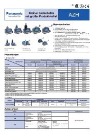
2 Form C<br />
mm inch<br />
Characteristics<br />
Initial insulation resistance* 1<br />
Between open contacts<br />
Initial<br />
breakdown<br />
Between contacts and coil<br />
voltage* 2 Between contacts and<br />
earth terminal<br />
Operate time* 3 (at nominal voltage)<br />
Release time* 3 (at nominal voltage)(without diode)<br />
Set time* 3 (at nominal voltage)<br />
Reset time* 3 (at nominal voltage)<br />
Temperature rise (at 20°C)<br />
Shock resistance<br />
Vibration resistance<br />
Conditions for operation,<br />
transport and storage<br />
(Not freezing and condensing<br />
at low temperature)<br />
Unit weight<br />
Functional* 4<br />
Destructive* 5<br />
Functional* 6<br />
Destructive<br />
Ambient<br />
temp.<br />
Humidity<br />
1 C type<br />
2 C type<br />
Min. 100 MΩ at 500 V DC<br />
1,000 Vrms<br />
2,000 Vrms<br />
500 Vrms<br />
Approx. 10 ms<br />
Approx. 5 ms<br />
Approx. 7 ms<br />
Approx. 7 ms<br />
Max. 55°C with nominal coil voltage<br />
across coil and at nominal switching capacity<br />
Min. 196 m/s 2 {20 G}<br />
Min. 980 m/s 2 {100 G}<br />
10 to 55 Hz<br />
at double amplitude of 2 mm<br />
10 to 55 Hz<br />
at double amplitude of 2 mm<br />
–50°C to 60°C<br />
–58°F to 140°F<br />
5 to 85%R.H.<br />
Approx. 8 g .282 oz<br />
Approx. 10 g .353 oz<br />
Remarks<br />
* Specifications will vary with foreign standards certification ratings.<br />
* 1 Measurement at same location as “Intial breakdown voltage” section<br />
* 2 Detection current: 10mA<br />
* 3 Excluding contact bounce time<br />
* 4 Half-wave pulse of sine wave: 11ms; detection time: 10µs<br />
* 5 Half-wave pulse of sine wave: 6ms<br />
* 6 Detection time: 10µs<br />
ORDERING INFORMATION<br />
Ex. <strong>RG</strong><br />
1 T L 5V<br />
Contact arrangement Characteristic impedance Operating function Coil voltage<br />
1:1 Form C<br />
2:2 Form C<br />
Nil: 75 Ω<br />
T: 50 Ω<br />
Nil: Single side<br />
Nil: stable<br />
L: 1 coil latching<br />
L2: 2 coil latching<br />
DC: 3, 5, 6,<br />
9, 12, 24,<br />
48 V<br />
Note: Standard packing; Carton: 50 pcs. Case 500 pcs.<br />
1
<strong>RG</strong><br />
TYPES ANE COIL DATA (at 20°C 68°F)<br />
1 Form C<br />
Single side stable<br />
Part No.<br />
<strong>RG</strong>1-3V<br />
<strong>RG</strong>1T-3V<br />
<strong>RG</strong>1-5V<br />
<strong>RG</strong>1T-5V<br />
<strong>RG</strong>1-6V<br />
<strong>RG</strong>1T-6V<br />
<strong>RG</strong>1-9V<br />
<strong>RG</strong>1T-9V<br />
<strong>RG</strong>1-12V<br />
<strong>RG</strong>1T-12V<br />
<strong>RG</strong>1-24V<br />
<strong>RG</strong>1T-24V<br />
<strong>RG</strong>1-48V<br />
<strong>RG</strong>1T-48V<br />
Nominal<br />
voltage<br />
V DC<br />
3<br />
5<br />
6<br />
9<br />
12<br />
24<br />
48<br />
Pick-up<br />
voltage, max.<br />
V DC<br />
2.4<br />
4.0<br />
4.8<br />
7.2<br />
9.6<br />
19.2<br />
38.4<br />
Drop-out<br />
voltage, min.<br />
V DC<br />
0.3<br />
0.5<br />
0.6<br />
0.9<br />
1.2<br />
2.4<br />
4.8<br />
Coil<br />
resistance,<br />
Ω (±10%)<br />
25.7<br />
71.4<br />
103<br />
231<br />
411<br />
1,646<br />
6,583<br />
Nominal<br />
operating<br />
current, mA<br />
117.3<br />
70.3<br />
58.3<br />
38.9<br />
29.2<br />
14.6<br />
7.3<br />
Nominal<br />
operating<br />
power, mW<br />
350<br />
350<br />
350<br />
350<br />
350<br />
350<br />
350<br />
Maximum<br />
allowable<br />
voltage, V DC<br />
(40°C 104°F)<br />
3.6<br />
6.0<br />
7.2<br />
10.8<br />
14.4<br />
28.8<br />
57.6<br />
1 coil latching<br />
Part No.<br />
<strong>RG</strong>1-L-3V<br />
<strong>RG</strong>1T-L-3V<br />
<strong>RG</strong>1-L-5V<br />
<strong>RG</strong>1T-L-5V<br />
<strong>RG</strong>1-L-6V<br />
<strong>RG</strong>1T-L-6V<br />
<strong>RG</strong>1-L-9V<br />
<strong>RG</strong>1T-L-9V<br />
<strong>RG</strong>1-L-12V<br />
<strong>RG</strong>1T-L-12V<br />
<strong>RG</strong>1-L-24V<br />
<strong>RG</strong>1T-L-24V<br />
<strong>RG</strong>1-L-48V<br />
<strong>RG</strong>1T-L-48V<br />
Nominal<br />
voltage<br />
V DC<br />
3<br />
5<br />
6<br />
9<br />
12<br />
24<br />
48<br />
Set and reset<br />
voltage,<br />
V DC (max.)<br />
2.4<br />
4.0<br />
4.8<br />
7.2<br />
9.6<br />
19.2<br />
38.4<br />
Coil<br />
resistance,<br />
Ω (±10%)<br />
51.4<br />
142.8<br />
206.8<br />
462.8<br />
822.8<br />
3,292.8<br />
13,166.8<br />
Nominal<br />
operating<br />
current, mA<br />
58.3<br />
35.8<br />
29.2<br />
19.4<br />
14.6<br />
7.3<br />
3.6<br />
Nominal<br />
operating<br />
power, mW<br />
175<br />
175<br />
175<br />
175<br />
175<br />
175<br />
175<br />
Maximum<br />
allowable<br />
voltage, V DC<br />
(40°C 104°F)<br />
3.6<br />
6.0<br />
7.2<br />
10.8<br />
14.4<br />
28.8<br />
57.6<br />
2 coil latching<br />
Part No.<br />
<strong>RG</strong>1-L2-3V<br />
<strong>RG</strong>1T-L2-3V<br />
<strong>RG</strong>1-L2-5V<br />
<strong>RG</strong>1T-L2-5V<br />
<strong>RG</strong>1-L2-6V<br />
<strong>RG</strong>1T-L2-6V<br />
<strong>RG</strong>1-L2-9V<br />
<strong>RG</strong>1T-L2-9V<br />
<strong>RG</strong>1-L2-12V<br />
<strong>RG</strong>1T-L2-12V<br />
<strong>RG</strong>1-L2-24V<br />
<strong>RG</strong>1T-L2-24V<br />
<strong>RG</strong>1-L2-48V<br />
<strong>RG</strong>1T-L2-48V<br />
Nominal<br />
voltage<br />
V DC<br />
3<br />
5<br />
6<br />
9<br />
12<br />
24<br />
48<br />
Set and reset Coil resistance, Ω (±10%)<br />
voltage,<br />
V DC (max.) Coil 1 Coil 2<br />
2.4<br />
25.7<br />
25.7<br />
4.0<br />
4.8<br />
7.2<br />
9.6<br />
19.2<br />
38.4<br />
71.4<br />
103<br />
231<br />
411<br />
1,646<br />
6,583<br />
71.4<br />
103<br />
231<br />
411<br />
1,646<br />
6,583<br />
Nominal<br />
operating<br />
current, mA<br />
117.8<br />
70.8<br />
58.3<br />
38.9<br />
29.2<br />
14.6<br />
7.3<br />
Nominal<br />
operating<br />
power, mW<br />
350<br />
350<br />
350<br />
350<br />
350<br />
350<br />
350<br />
Maximum<br />
allowable<br />
voltage, V DC<br />
(40°C 104°F)<br />
3.6<br />
6.0<br />
7.2<br />
10.8<br />
14.4<br />
28.8<br />
57.6<br />
2 Form C<br />
Single side stable<br />
Part No.<br />
<strong>RG</strong>2-3V<br />
<strong>RG</strong>2T-3V<br />
<strong>RG</strong>2-5V<br />
<strong>RG</strong>2T-5V<br />
<strong>RG</strong>2-6V<br />
<strong>RG</strong>2T-6V<br />
<strong>RG</strong>2-9V<br />
<strong>RG</strong>2T-9V<br />
<strong>RG</strong>2-12V<br />
<strong>RG</strong>2T-12V<br />
<strong>RG</strong>2-24V<br />
<strong>RG</strong>2T-24V<br />
<strong>RG</strong>2-48V<br />
<strong>RG</strong>2T-48V<br />
Nominal<br />
voltage<br />
V DC<br />
3<br />
5<br />
6<br />
9<br />
12<br />
24<br />
48<br />
Pick-up<br />
voltage, max.<br />
V DC<br />
2.4<br />
4.0<br />
4.8<br />
7.2<br />
9.6<br />
19.2<br />
38.4<br />
Drop-out<br />
voltage, min.<br />
V DC<br />
0.3<br />
0.5<br />
0.6<br />
0.9<br />
1.2<br />
2.4<br />
4.8<br />
Coil<br />
resistance,<br />
Ω (±10%)<br />
22.5<br />
62.5<br />
90<br />
202.5<br />
360<br />
1,440<br />
5,760<br />
Nominal<br />
operating<br />
current, mA<br />
133.8<br />
80.8<br />
66.7<br />
44.4<br />
33.3<br />
16.7<br />
8.3<br />
Nominal<br />
operating<br />
power, mW<br />
400<br />
400<br />
400<br />
400<br />
400<br />
400<br />
400<br />
Maximum<br />
allowable<br />
voltage, V DC<br />
(40°C 104°F)<br />
3.6<br />
6.0<br />
7.2<br />
10.8<br />
14.4<br />
28.8<br />
57.6<br />
2
<strong>RG</strong><br />
1 coil latching<br />
Part No.<br />
<strong>RG</strong>2-L-3V<br />
<strong>RG</strong>2T-L-3V<br />
<strong>RG</strong>2-L-5V<br />
<strong>RG</strong>2T-L-5V<br />
<strong>RG</strong>2-L-6V<br />
<strong>RG</strong>2T-L-6V<br />
<strong>RG</strong>2-L-9V<br />
<strong>RG</strong>2T-L-9V<br />
<strong>RG</strong>2-L-12V<br />
<strong>RG</strong>2T-L-12V<br />
<strong>RG</strong>2-L-24V<br />
<strong>RG</strong>2T-L-24V<br />
<strong>RG</strong>2-L-48V<br />
<strong>RG</strong>2T-L-48V<br />
Nominal<br />
voltage<br />
V DC<br />
3<br />
5<br />
6<br />
9<br />
12<br />
24<br />
48<br />
Set and reset<br />
voltage,<br />
V DC (max.)<br />
2.4<br />
4.0<br />
4.8<br />
7.2<br />
9.6<br />
19.2<br />
38.4<br />
Coil<br />
resistance,<br />
Ω (±10%)<br />
45<br />
125<br />
180<br />
405<br />
720<br />
2,880<br />
11,520<br />
Nominal<br />
operating<br />
current, mA<br />
66.7<br />
40.8<br />
33.3<br />
22.2<br />
16.7<br />
8.3<br />
4.2<br />
Nominal<br />
operating<br />
power, mW<br />
200<br />
200<br />
200<br />
200<br />
200<br />
200<br />
200<br />
Maximum<br />
allowable<br />
voltage, V DC<br />
(40°C 104°F)<br />
3.6<br />
6.0<br />
7.2<br />
10.8<br />
14.4<br />
28.8<br />
57.6<br />
2 coil latching<br />
Part No.<br />
<strong>RG</strong>2-L2-3V<br />
<strong>RG</strong>2T-L2-3V<br />
<strong>RG</strong>2-L2-5V<br />
<strong>RG</strong>2T-L2-5V<br />
<strong>RG</strong>2-L2-6V<br />
<strong>RG</strong>2T-L2-6V<br />
<strong>RG</strong>2-L2-9V<br />
<strong>RG</strong>2T-L2-9V<br />
<strong>RG</strong>2-L2-12V<br />
<strong>RG</strong>2T-L2-12V<br />
<strong>RG</strong>2-L2-24V<br />
<strong>RG</strong>2T-L2-24V<br />
<strong>RG</strong>2-L2-48V<br />
<strong>RG</strong>2T-L2-48V<br />
Nominal<br />
voltage<br />
V DC<br />
3<br />
5<br />
6<br />
9<br />
12<br />
24<br />
48<br />
Set and reset Coil resistance, Ω (±10%)<br />
voltage,<br />
V DC (max.) Coil 1 Coil 2<br />
2.4<br />
22.5<br />
22.5<br />
4.0<br />
4.8<br />
7.2<br />
9.6<br />
19.2<br />
38.4<br />
62.5<br />
90<br />
203<br />
360<br />
1,440<br />
5,760<br />
62.5<br />
90<br />
202.5<br />
360<br />
1,440<br />
5,760<br />
Nominal<br />
operating<br />
current, mA<br />
133.8<br />
80.8<br />
66.7<br />
44.4<br />
33.3<br />
16.7<br />
8.3<br />
Nominal<br />
operating<br />
power, mW<br />
400<br />
400<br />
400<br />
400<br />
400<br />
400<br />
400<br />
Maximum<br />
allowable<br />
voltage, V DC<br />
(40°C 104°F)<br />
3.6<br />
6.0<br />
7.2<br />
10.8<br />
14.4<br />
28.8<br />
57.6<br />
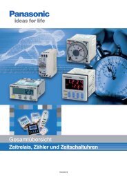
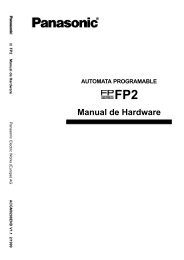
DIMENSIONS<br />
mm inch<br />
1 Form C type<br />
21<br />
.827<br />
5.08<br />
15.24 .200<br />
.600<br />
20.32<br />
.800 25<br />
.984<br />
3–0.5×0.4<br />
.020×.016<br />
2.61<br />
.103<br />
15<br />
.591<br />
7.62<br />
.300<br />
19<br />
.748<br />
2.54<br />
.100<br />
9.9<br />
.390<br />
0.5<br />
.020<br />
3.7<br />
.146<br />
PC board pattern (Copper-side view)<br />
2.54<br />
2.54<br />
.100<br />
.100<br />
11-1 DIA<br />
11-.039 DIA.<br />
Tolerance: ±0.1 ±.004<br />
Schematic (Bottom view)<br />
Deenergized condition Reset condition Reset condition<br />
4–0.4×0.25<br />
.016×.010<br />
4–0.4×0.4<br />
.016×.016<br />
Tolerance: ±0.3 ±.012<br />
1 2 3 4 5 6 7 1 2 3 4 5 6 7 1 2 3 4 5 6 7<br />
– 15<br />
17<br />
+ 15<br />
17<br />
– 15<br />
+ 16<br />
18<br />
– 16<br />
18<br />
Single side stable 1 coil latching 2 coil latching<br />
Set coil<br />
17<br />
+ 16<br />
18 –<br />
+<br />
Reset coil<br />
3
<strong>RG</strong><br />
2 Form C type<br />
mm inch<br />
21<br />
.827<br />
5.08<br />
15.24 .200<br />
.600<br />
20.32<br />
.800 25<br />
.984<br />
6–0.5×0.4<br />
.020×.016<br />
19<br />
.748<br />
2.54<br />
.100<br />
17.78<br />
.700<br />
23<br />
.906<br />
9.4<br />
.370<br />
0.5<br />
.020<br />
3.7<br />
.146<br />
PC board pattern (Copper-side view)<br />
2.54<br />
.100<br />
18-1 DIA<br />
18-.039 DIA.<br />
2.54<br />
.100<br />
Tolerance: ±0.1 ±.004<br />
8–0.4×0.25<br />
.016×.010<br />
4–0.4×0.4<br />
.016×.016<br />
Schematic (Bottom view)<br />
1 2 3 4 5 6 7 1 2 3 4 5 6 7<br />
– 15<br />
17<br />
+ 15<br />
17<br />
+ 16<br />
18<br />
– 16<br />
18<br />
Set coil<br />
1 2 3 4 5 6 7<br />
– 15<br />
17 +<br />
+ 16<br />
18 –<br />
Reset coil<br />
8 9 10 11 12 13 14<br />
8 9 10 11 12 13 14<br />
8 9 10 11 12 13 14<br />
General tolerance: ±0.3 ±.012<br />
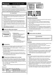
REFERENCE DATA<br />
1. Isolation<br />
<strong>RG</strong>2-12V<br />
75 Ω characteristic impedance<br />
100<br />
<strong>RG</strong>2T-12V<br />
50 Ω characteristic impedance<br />
100<br />
Single side stable<br />
1 coil latching 2 coil latching<br />
Deenergized condition Reset condition Reset condition<br />
Isolation, dB<br />
50<br />
Isolation, dB<br />
50<br />
0 500<br />
1000<br />
Frequency, MHz<br />
0 500<br />
1000<br />
Frequency, MHz<br />
2. Insertion loss<br />
<strong>RG</strong>2-12V<br />
75 Ω characteristic impedance<br />
<strong>RG</strong>2T-12V<br />
50 Ω characteristic impedance<br />
Insertion loss, dB<br />
5<br />
Insertion loss, dB<br />
5<br />
0<br />
0<br />
0 500<br />
1000<br />
Frequency, MHz<br />
0 500<br />
1000<br />
Frequency, MHz<br />
4
3. Return loss<br />
<strong>RG</strong>2-12V<br />
75 Ω characteristic impedance<br />
<strong>RG</strong>2T-12V<br />
50 Ω characteristic impedance<br />
<strong>RG</strong><br />
100<br />
100<br />
Return loss, dB<br />
50<br />
Return loss, dB<br />
50<br />
0 500<br />
1000<br />
Frequency, MHz<br />
0 500<br />
1000<br />
Frequency, MHz<br />
4-(1). Operate and release time (1C)<br />
<strong>RG</strong>1-12V 6 pcs.<br />
4-(2). Set and reset time (1C)<br />
<strong>RG</strong>1-L2-12V 6 pcs.<br />
4-(3). Operate and release time<br />
(Without diode) (2C)<br />
<strong>RG</strong>2-12V 6 pcs.<br />
Operate and release time, ms<br />
15<br />
10<br />
5<br />
Operate time<br />
Release time<br />
Max.<br />
Max.<br />
x<br />
Min.<br />
Min.<br />
Set and reset time, ms<br />
15<br />
10<br />
5<br />
Set time<br />
Reset time<br />
Max.<br />
Max.<br />
x<br />
Min.<br />
Min.<br />
Operate and release time, ms<br />
15<br />
10<br />
5<br />
Operate time<br />
Release time<br />
Max.<br />
Max.<br />
x<br />
Min.<br />
Min.<br />
0<br />
80<br />
100 120<br />
Coil voltage, %V<br />
0<br />
80 100 120<br />
Coil voltage, %V<br />
0<br />
80<br />
100 120<br />
Coil voltage, %V<br />
4-(4). Set and reset time (2C)<br />
<strong>RG</strong>2-L2-12V 6 pcs.<br />
5-(1). Bounce time (2C)<br />
<strong>RG</strong>2-12V 100 pcs.<br />
Nominal voltage is applied.<br />
Set and reset time, ms<br />
15<br />
10<br />
5<br />
Set time<br />
Reset time<br />
Max.<br />
Max.<br />
x<br />
Min.<br />
Min.<br />
Frequency<br />
100<br />
50<br />
Operate bounce<br />
Frequency<br />
100<br />
50<br />
Release bounce<br />
0<br />
80<br />
100 120<br />
Coil voltage, %V<br />
0<br />
0<br />
0.5 1.0 1.5 2.0 2.5<br />
Operate bounce, ms<br />
0 0 0.5 1.0 1.5 2.0 2.5<br />
Release bounce, ms<br />
5-(2). Bounce time (2C)<br />
<strong>RG</strong>2-L2-12V 100 pcs.<br />
Nominal voltage is applied.<br />
100<br />
Set bounce<br />
100<br />
Reset bounce<br />
Frequency<br />
50<br />
Frequency<br />
50<br />
0<br />
0<br />
0.5 1.0 1.5 2.0 2.5<br />
Set bounce, ms<br />
0<br />
0<br />
0.5 1.0 1.5 2.0 2.5<br />
Reset bounce, ms<br />
5
<strong>RG</strong><br />
6-(1). Mechanical life (1C)<br />
<strong>RG</strong>1-12V 12 pcs.<br />
6-(2). Mechanical life (1C latching type)<br />
<strong>RG</strong>1-L2-12V 6 pcs.<br />
Pick-up and drop-out voltage<br />
10<br />
8<br />
6<br />
4<br />
2<br />
0<br />
Pick-up voltage<br />
Drop-out voltage<br />
100 200 300 400<br />
No. of operations, ×10 4<br />
Max.<br />
x<br />
Min.<br />
Max.<br />
x<br />
Min.<br />
500<br />
Set and reset voltage, V<br />
10<br />
8<br />
6<br />
4<br />
2<br />
0<br />
Set voltage<br />
Reset voltage<br />
100 200 300 400 500<br />
No. of operations, ×10 4<br />
Max.<br />
Max.<br />
x<br />
Min.<br />
Min.<br />
7-(1). <strong>Electric</strong>al life (10 mA 24 V DC<br />
resistive load)<br />
<strong>RG</strong>2-12V 6 pcs.<br />
7-(2). <strong>Electric</strong>al life (1 A 24 V DC resistive<br />
load)<br />
<strong>RG</strong>2-12V 6 pcs.<br />
100<br />
100<br />
Contact resistance, mΩ<br />
80<br />
60<br />
40<br />
Max.<br />
x<br />
Min.<br />
Contact resistance, mΩ<br />
80<br />
60<br />
40<br />
Max.<br />
x<br />
Min.<br />
20<br />
20<br />
0<br />
2 4 6 8 10<br />
No. of operations, ×10 4<br />
0<br />
2 4 6 8 10<br />
No. of operations, ×10 4<br />
8-(1). Rate of change in pick-up and drop-out<br />
voltage (1C)<br />
<strong>RG</strong>1-12V 5 pcs.<br />
<strong>RG</strong>1-L2-12V 5 pcs.<br />
Rate of change, %<br />
40<br />
30<br />
20<br />
10<br />
0<br />
–10<br />
Pick-up voltage<br />
Drop-out voltage<br />
Rate of change, %<br />
40<br />
30<br />
20<br />
10<br />
0<br />
–10<br />
Set voltage<br />
Reset voltage<br />
–20<br />
–20<br />
–30<br />
–30<br />
–40 –20 0 20 40 60 80<br />
Ambient temperature, °C<br />
–40 –20 0 20 40 60 80<br />
Ambient temperature, °C<br />
8-(2). Rate of change in pick-up and drop-out<br />
voltage (2C)<br />
<strong>RG</strong>2-12V 5 pcs.<br />
<strong>RG</strong>2-L2-12V 5 pcs.<br />
40<br />
40<br />
Rate of change, %<br />
30<br />
20<br />
10<br />
0<br />
–10<br />
–20<br />
Pick-up voltage<br />
Drop-out voltage<br />
Rate of change, %<br />
30<br />
20<br />
10<br />
0<br />
–10<br />
–20<br />
Set voltage<br />
Reset voltage<br />
–30<br />
–30<br />
–40 –20 0 20 40 60 80<br />
Ambient temperature, °C<br />
–40 –20 0 20 40 60 80<br />
Ambient temperature, °C<br />
6
Test condition<br />
mm inch<br />
<strong>RG</strong><br />
Spectrum analyzer<br />
<strong>RG</strong> relay<br />
Measurement tool<br />
50 Ω or 75 Ω<br />
NM type connector<br />
1. Characteristic impedance of all the<br />
measuring devices (signal generator<br />
and cable) is 50Ω or 75Ω.<br />
2. The PC board for the test is double<br />
side copper clad phenolic paper<br />
laminate with thickness of 1.6 mm.<br />
3. Grounding terminal holes are plated<br />
through.<br />
4. Grounding terminal and one of the<br />
coil terminals are soldered to the PC<br />
board to be grounded.<br />
5. Connection with measurement instrument<br />
is made with semi-rigid cable<br />
(Uniform Tube UT 141A) and<br />
high frequency NM type connector.<br />
70 40<br />
2.756 1.575<br />
40<br />
1.575<br />
70<br />
2.756<br />
A<br />
PC board pattern<br />
1.5 dia.<br />
.059<br />
1.0 dia.<br />
.039<br />
2.5<br />
.098<br />
3.5<br />
.138<br />
Expanslon of A<br />
NOTES<br />
1. Soldering<br />
Perform soldering under the conditions<br />
below.<br />
• Within 10s at 250°C 482°F<br />
• Within 5s at 300°C 572°F<br />
• Within 3s at 350°C 662°F<br />
2. Counter voltage of DC relays<br />
If input is cut off in DC relays, a<br />
counter voltage is developed across<br />
the coil as a result of the collapse of<br />
the magnetic field. If the coil is used in<br />
a transistor circuit, the reverse voltage<br />
produced from the coil can cause a<br />
serious circuit malfunction.<br />
This counter voltage can be reduced<br />
considerably by connecting a capacitor<br />
or a diode in parallel with the coil.<br />
The level of reduction must be determined<br />
either by calculation if the coil<br />
data is available or by experiment.<br />
(1) Capacitor<br />
E<br />
SW<br />
Capacitor<br />
Relay Ry<br />
r<br />
(2) Diode<br />
SW<br />
Diode<br />
Relay Ry<br />
E<br />
3. Latching relay<br />
In order to assure proper operating<br />
regardless of changes in the ambient<br />
usage temperature and usage conditions,<br />
nominal operating voltage should be<br />
applied to the coil for more than 40 ms to<br />
set/reset the latching type relay.<br />
For Cautions for Use, see Relay Technical Information in catalog.<br />
7