PDF data sheet - Panasonic Electric Works Europe AG
PDF data sheet - Panasonic Electric Works Europe AG
PDF data sheet - Panasonic Electric Works Europe AG

You also want an ePaper? Increase the reach of your titles
YUMPU automatically turns print PDFs into web optimized ePapers that Google loves.
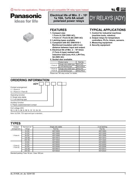
Not for new applications. Please order pin-compatible DK relay types instead.<br />
<strong>Electric</strong>al life of Min. 2 10 5<br />
1a 10A, 1a1b 8A small<br />
polarized power relays<br />
DY<br />
DY RELAYS (ADY)<br />
FEATURES<br />
1. Compact size:<br />
1 Form A (10A 250V AC),<br />
1 Form A 1 Form B (8A 250V AC)<br />
2. Latching types available<br />
3. Compliant with IEC EN61010-1.<br />
Reinforced insulation with 6 mm<br />
distance between input and output.<br />
4. <strong>Electric</strong>al life of Min. 2 10 5 times<br />
(1 Form A type) realized with<br />
inductive load (cos=0.4, L/R=7ms,<br />
5A 250V AC)<br />
5. Socket also available.<br />
Product name<br />
Part No.<br />
Single side stable type DK1a-PS<br />
1 Form A<br />
2 coil latching type DK1a-PSL2<br />
1 Form A Single side stable type DK2a-PS<br />
1 Form B 2 coil latching type DK2a-PSL2<br />
Please see “DK relay socket” for details.<br />
TYPICAL APPLICATIONS<br />
1. Control for industrial machines<br />
(machine tools, robotics)<br />
2. Output relays for temperature<br />
controllers, PLCs, timers, sensors.<br />
3. Measuring equipment<br />
4. Security equipment<br />
ORDERING INFORMATION<br />
Contact arrangement<br />
1: 1 Form A<br />
3: 1 Form A 1 Form B<br />
Operating function<br />
0: Single side stable<br />
2: 2 coil latching type<br />
ADY<br />
Auxiliary function<br />
0: Plastic sealed/standard contact<br />
Coil voltage (DC)<br />
03: 3, 05: 5, 06: 6, 09: 9, 12: 12, 24: 24<br />
Note: UL/CSA, TÜV approved type is standard.<br />
TYPES<br />
Contact<br />
arrangement<br />
1 Form A<br />
1 Form A<br />
1 Form B<br />
Nominal coil<br />
voltage<br />
Standard packing: Tube: 50 pcs.; Case: 500 pcs.<br />
Single side stable<br />
Part No.<br />
2 coil latching<br />
Part No.<br />
3V DC ADY10003 ADY12003<br />
5V DC ADY10005 ADY12005<br />
6V DC ADY10006 ADY12006<br />
12V DC ADY10012 ADY12012<br />
24V DC ADY10024 ADY12024<br />
3V DC ADY30003 ADY32003<br />
5V DC ADY30005 ADY32005<br />
6V DC ADY30006 ADY32006<br />
12V DC ADY30012 ADY32012<br />
24V DC ADY30024 ADY32024<br />
ds_61A06_en_dy: 020413D<br />
1
DY Not for new applications. Please order pin-compatible DK relay types instead.<br />
RATING<br />
1. Coil <strong>data</strong><br />
1) Single side stable<br />
Nominal coil<br />
voltage<br />
3V DC<br />
2) 2 coil latching<br />
2. Specifications<br />
Pick-up voltage<br />
(at 20C 68F)<br />
Drop-out voltage<br />
(at 20C 68F)<br />
Nominal operating<br />
current<br />
[10%] (at 20C 68F)<br />
66.6mA<br />
Coil resistance<br />
[10%] (at 20C 68F)<br />
45<br />
5V DC<br />
6V DC<br />
12V DC<br />
70%V or less of<br />
nominal voltage<br />
(Initial)<br />
10%V or more of<br />
nominal voltage<br />
(Initial)<br />
40mA<br />
33.3mA<br />
16.6mA<br />
125<br />
180<br />
720<br />
24V DC 8.3mA 2,880<br />
Nominal coil<br />
voltage<br />
Set voltage<br />
(at 20C 68F)<br />
Reset voltage<br />
(at 20C 68F)<br />
Nominal operating<br />
current<br />
[10%] (at 20C 68F)<br />
Coil resistance<br />
[10%] (at 20C 68F)<br />
Nominal operating<br />
power<br />
200mW<br />
Nominal operating<br />
power<br />
Set coil Reset coil Set coil Reset coil Set coil Reset coil<br />
3V DC<br />
5V DC<br />
6V DC<br />
12V DC<br />
70%V or less of<br />
nominal voltage<br />
(Initial)<br />
70%V or less of<br />
nominal voltage<br />
(Initial)<br />
66.6mA<br />
40mA<br />
33.3mA<br />
16.6mA<br />
66.6mA<br />
40mA<br />
33.3mA<br />
16.6mA<br />
45<br />
125<br />
180<br />
720<br />
45<br />
125<br />
180<br />
720<br />
200mW 200mW<br />
24V DC 8.3mA 8.3mA 2,880 2,880<br />
Max. allowable voltage<br />
(at 20C 68F)<br />
130%V of<br />
nominal voltage<br />
Max. allowable voltage<br />
(at 20C 68F)<br />
130%V of<br />
nominal voltage<br />
Characteristics Item Specifications<br />
Arrangement 1 Form A 1 Form A 1 Form B<br />
Contact<br />
Initial contact resistance, max. Max. 30 m (By voltage drop 6 V DC 1A)<br />
Contact material<br />
Au-flashed AgSnO2 type<br />
Resistive load 10A 250V AC, 10A 30V DC 8A 250V AC, 8A 30V DC<br />
Nominal switching<br />
capacity<br />
Inductive load<br />
5A 250V AC<br />
3.5A 250V AC<br />
(cos = 0.4, L/R = 7ms)<br />
Max. switching Resistive load 2,500V A, 300W 2,000V A, 240W<br />
Rating<br />
capacity<br />
Inductive load<br />
(Reference value) (cos = 0.4, L/R = 7ms)<br />
1,250V A 875V A<br />
Max. switching voltage<br />
380V AC, 125V DC<br />
Max. switching current 10 A 8 A<br />
Min. switching capacity (Reference value) *1<br />
5V 10mA<br />
Nominal operating power<br />
200 mW<br />
Insulation resistance (Initial)<br />
Min. 1,000M (at 500V DC)<br />
Measurement at same location as “Initial breakdown voltage” section.<br />
Breakdown voltage Between open contacts<br />
1,000 Vrms for 1 min. (Detection current: 10 mA)<br />
(Initial)<br />
Between contact and coil<br />
4,000 Vrms for 1 min. (Detection current: 10 mA)<br />
<strong>Electric</strong>al<br />
characteristics<br />
Mechanical<br />
characteristics<br />
Expected life<br />
Conditions<br />
Unit weight<br />
Notes<br />
Surge breakdown<br />
Between contact and coil<br />
voltage *2<br />
Temperature rise (at70C 158F)<br />
Operate time [Set time] (at 20C 68F)<br />
Release time [Reset time] (at 20C 68F)<br />
Shock resistance<br />
Functional<br />
Destructive<br />
10,000 V (initial)<br />
Max. 40C (By resistive method, nominal voltage applied to the coil; max. switching current)<br />
Max. 10 ms [10 ms] (Nominal voltage applied to the coil, excluding contact bounce time.)<br />
Max. 8 ms [10 ms] (Nominal voltage applied to the coil, excluding contact bounce time.)<br />
(without diode)<br />
Min. 98 m/s 2 (Half-wave pulse of sine wave: 11 ms; detection time: 10s.)<br />
Min. 980 m/s 2 (Half-wave pulse of sine wave: 6 ms.)<br />
Vibration resistance<br />
Functional 10 to 55 Hz at double amplitude of 1.5 mm (Detection time: 10s.)<br />
Destructive<br />
10 to 55 Hz at double amplitude of 3 mm<br />
Mechanical<br />
Min. 510 7 (at 300 times/min.)<br />
Min. 210 5 : 1 Form A inductive load (at 20 times/min.) (at rated load);<br />
<strong>Electric</strong>al<br />
Min. 10 5 : 1 Form A resistive load, 1 Form A 1 Form B resistive load, 1 Form A 1 Form B<br />
inductive load (at 20 times/min.) (at rated load)<br />
Conditions for operation, transport and storage *3<br />
Ambient temperature: –40C to +70C –40F to +158F;<br />
Humidity: 5 to 85% R.H. (Not freezing and condensing at low temperature)<br />
Max. operating speed (at rated load)<br />
20 (times/min.)<br />
Approx. 6g .21oz<br />
*1 This value can change due to the switching frequency, environmental conditions, and desired reliability level, therefore it is recommended to check this with the actual load<br />
*2 Wave is standard shock voltage of 1.250s according to JEC-212-1981.<br />
*3 Refer to “6. Usage, Storage and Transport Conditions“ in AMBIENT ENVIRONMENT section in Relay Technical Information.<br />
2 ds_61A06_en_dy: 020413D
Not for new applications. Please order pin-compatible DK relay types instead.<br />
REFERENCE DATA<br />
1-(1). Maximum switching capacity<br />
(1 Form A)<br />
Tested sample: ADY10024<br />
1-(2). Maximum switching capacity<br />
(1 Form A 1 Form B)<br />
Tested sample: ADY30024<br />
DY<br />
2. Life curve (1 Form A, 1 Form A 1 Form B)<br />
Tested sample: ADY10024 (1 Form A),<br />
ADY30024 (1 Form A 1 Form B)<br />
500<br />
Contact current, A<br />
10<br />
5<br />
1<br />
0.1<br />
DC resistive load<br />
DC inductive<br />
load<br />
(L/R=7ms)<br />
AC resistive load<br />
AC inductive<br />
load<br />
(cosϕ=0.4)<br />
10 100 1,000<br />
Contact voltage, V<br />
Contact current, A<br />
10<br />
5<br />
1<br />
0.1<br />
DC resistive load<br />
DC inductive<br />
load<br />
(L/R=7ms)<br />
AC resistive load<br />
AC inductive<br />
load<br />
(cosϕ=0.4)<br />
10 30 100 1,000<br />
Contact voltage, V<br />
Life, ×10 4<br />
100<br />
ADY30024<br />
250V AC resistive load<br />
30V DC resistive load<br />
ADY10024<br />
250V AC resistive load<br />
30V DC resistive load<br />
10 ADY30024<br />
AC250V inductive<br />
load<br />
ADY10024<br />
(cosϕ=0.4) 250V AC inductive load<br />
DC 30V inductive (cosϕ=0.4)<br />
load<br />
30V DC inductive load<br />
(L/R=7ms) (L/R=7ms)<br />
1<br />
0 1 2 3 4 5 6 7 8 9 10<br />
Contact current, A<br />
3-(1). Coil temperature rise<br />
(1 Form A)<br />
Tested sample: ADY10024, 6 pcs.<br />
Ambient temperature: 20C, 68F<br />
50<br />
3-(2). Coil temperature rise<br />
(1 Form A 1 Form B)<br />
Tested sample: ADY30024, 6 pcs.<br />
Ambient temperature: 20C, 68F<br />
50<br />
4-(1). Ambient temperature characteristics<br />
(1 Form A)<br />
Tested sample: ADY10024, 6 pcs.<br />
Ambient temperature: –40C to 70C –40F to 158F<br />
15<br />
Temperature rise, °C<br />
40<br />
30<br />
20<br />
10A<br />
0A<br />
Temperature rise, °C<br />
40<br />
30<br />
20<br />
8A<br />
0A<br />
-40<br />
-20<br />
Variation<br />
ratio, %<br />
10<br />
5<br />
0<br />
0 20<br />
-5<br />
Pick up voltage<br />
Drop out voltage<br />
40 60 80<br />
Ambient<br />
temperature, °C<br />
10<br />
10<br />
-10<br />
0<br />
80 90 100 110 120 130<br />
Coil applied voltage, %V<br />
0<br />
80 90 100 110 120 130<br />
Coil applied voltage, %V<br />
-15<br />
4-(2). Ambient temperature characteristics<br />
(1 Form A 1 Form B)<br />
Tested sample: ADY30024, 6 pcs.<br />
Ambient temperature: –40C to 70C –40F to 158F<br />
15<br />
Variation<br />
ratio, %<br />
10<br />
5<br />
Pick up voltage<br />
-40<br />
-20<br />
0<br />
0 20<br />
-5<br />
Drop out voltage<br />
40 60<br />
Ambient<br />
temperature, °C<br />
80<br />
-10<br />
-15<br />
ds_61A06_en_dy: 020413D<br />
3
DY Not for new applications. Please order pin-compatible DK relay types instead.<br />
DIMENSIONS(mm inch)<br />
Download<br />
CAD Data<br />
from our Web site.<br />
1. 1 Form A type<br />
CAD Data<br />
External dimensions<br />
Single side stable type<br />
9.7<br />
.382<br />
20 15<br />
.787 .591<br />
3.5<br />
0.3<br />
.138<br />
.012<br />
0.4<br />
.016<br />
0.8<br />
.031<br />
0.8<br />
.031<br />
0.4<br />
.016<br />
10.16 7.62 1.11 2.42 10.16<br />
.400 .300 .044 .095 .400<br />
PC board pattern<br />
(BOTTOM VIEW)<br />
Single side stable type<br />
2-0.9 dia.<br />
2-.035 dia.<br />
10.16<br />
.400<br />
10.16<br />
.400<br />
7.62<br />
.300<br />
4-1.1 dia.<br />
4-.043 dia.<br />
Schematic<br />
(BOTTOM VIEW)<br />
Single side stable<br />
1 3 4<br />
-<br />
+<br />
8<br />
(Deenergized condition)<br />
2 coil latching type<br />
20<br />
.787<br />
15<br />
.591<br />
2 coil latching type<br />
2-0.9 dia.<br />
2-.035 dia. 2.54 7.62<br />
.100 .300<br />
7.62<br />
.300<br />
5-1.1 dia.<br />
5-.043 dia.<br />
2 coil latching type<br />
1 3 4<br />
-<br />
9.7<br />
.382<br />
0.3<br />
.012<br />
0.4<br />
.016<br />
0.4<br />
.016<br />
0.8<br />
.031<br />
0.8<br />
.031<br />
2.54 7.62 7.62 1.11<br />
.100 .300 .300 .044<br />
3.5<br />
.138<br />
2.42<br />
.095<br />
10.16<br />
.400<br />
0.4<br />
.016<br />
10.16<br />
.400<br />
+ +<br />
8 7<br />
(Reset condition)<br />
Since this is a polarized relay,<br />
the connection to the coil<br />
should be done according to<br />
the above schematic.<br />
General tolerance: 0.3 .012<br />
Tolerance: 0.1 .004<br />
2. 1 Form A 1 Form B type<br />
External dimensions<br />
CAD Data Single side stable type<br />
9.7<br />
.382<br />
2 coil latching type<br />
20 15<br />
.787 .591<br />
3.5<br />
0.3<br />
.138<br />
.012<br />
0.4<br />
.016<br />
0.8<br />
.031<br />
0.8<br />
.031<br />
0.4<br />
.016<br />
10.16 7.62 1.11 2.42 10.16<br />
.400 .300 .044 .095 .400<br />
9.7<br />
.382<br />
20<br />
.787<br />
0.3<br />
.012<br />
0.4<br />
.016<br />
0.4<br />
.016<br />
0.8<br />
.031<br />
0.8<br />
.031<br />
2.54 7.62 7.62 1.11<br />
.100 .300 .300 .044<br />
3.5<br />
.138<br />
2.42<br />
.095<br />
15<br />
.591<br />
10.16<br />
.400<br />
0.4<br />
.016<br />
PC board pattern<br />
(BOTTOM VIEW)<br />
Single side stable type<br />
2-0.9 dia.<br />
2-.035 dia.<br />
10.16<br />
.400<br />
10.16<br />
.400<br />
2 coil latching type<br />
2-0.9 dia.<br />
2-.035 dia. 2.54<br />
.100<br />
10.16<br />
.400<br />
7.62<br />
.300<br />
7.62<br />
.300<br />
7.62<br />
.300<br />
4-1.1 dia.<br />
4-.043 dia.<br />
5-1.1 dia.<br />
5-.043 dia.<br />
Schematic<br />
(BOTTOM VIEW)<br />
Single side stable<br />
1 3 4<br />
-<br />
+<br />
8 6 5<br />
(Deenergized condition)<br />
2 coil latching type<br />
1 3 4<br />
-<br />
+ +<br />
8 7 6 5<br />
(Reset condition)<br />
Since this is a polarized relay,<br />
the connection to the coil<br />
should be done according to<br />
the above schematic.<br />
General tolerance: 0.3 .012<br />
Tolerance: 0.1 .004<br />
SAFETY STANDARDS<br />
1 Form A<br />
Item<br />
1 Form A 1 Form B<br />
UL/C-UL (Recognized) CSA (Certified) TÜV (Certified)<br />
File No. Contact rating File No. Contact rating File No. Rating<br />
E43028<br />
E43028<br />
10A 250V AC<br />
1<br />
/3HP 125, 250V AC<br />
10A 30V DC<br />
8A 250V AC<br />
1<br />
/4HP 125, 250V AC<br />
8A 30V DC<br />
LR26550<br />
etc.<br />
LR26550<br />
etc.<br />
10A 250V AC<br />
1<br />
/3HP 125, 250V AC<br />
10A 30V DC<br />
8A 250V AC<br />
1<br />
/4HP 125, 250V AC<br />
8A 30V DC<br />
B 04 06<br />
13461 038<br />
B 04 06<br />
13461 038<br />
10A 250V AC (cos=1.0)<br />
10A 30V DC (0ms)<br />
8A 250V AC (cos=1.0)<br />
8A 30V DC (0ms)<br />
4 ds_61A06_en_dy: 020413D
Not for new applications. Please order pin-compatible DK relay types instead.<br />
NOTES<br />
1. Soldering should be done under the<br />
following conditions:<br />
250C 482F within 10s<br />
300C 572F within 5s<br />
350C 662F within 3s<br />
Soldering depth: 2/3 terminal pitch<br />
2. External magnetic field<br />
Since DY relays are highly sensitive<br />
polarized relays, their characteristics will<br />
be affected by a strong external magnetic<br />
field. Avoid using the relay under that<br />
condition.<br />
3. When using, please be aware that<br />
the A contact and B contact sides of<br />
1 Form A and 1 Form B types may go<br />
on simultaneously at operate time and<br />
release time.<br />
For Cautions for Use, see Relay Technical Information.<br />
DY<br />
ds_61A06_en_dy: 020413D<br />
5