RG-RELAYS - Panasonic Electric Works CZ
RG-RELAYS - Panasonic Electric Works CZ
RG-RELAYS - Panasonic Electric Works CZ

Create successful ePaper yourself
Turn your PDF publications into a flip-book with our unique Google optimized e-Paper software.
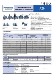
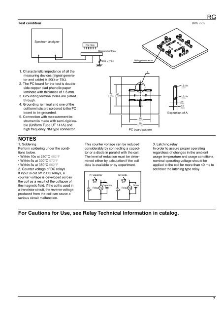
Test condition<br />
mm inch<br />
<strong>RG</strong><br />
Spectrum analyzer<br />
<strong>RG</strong> relay<br />
Measurement tool<br />
50 Ω or 75 Ω<br />
NM type connector<br />
1. Characteristic impedance of all the<br />
measuring devices (signal generator<br />
and cable) is 50Ω or 75Ω.<br />
2. The PC board for the test is double<br />
side copper clad phenolic paper<br />
laminate with thickness of 1.6 mm.<br />
3. Grounding terminal holes are plated<br />
through.<br />
4. Grounding terminal and one of the<br />
coil terminals are soldered to the PC<br />
board to be grounded.<br />
5. Connection with measurement instrument<br />
is made with semi-rigid cable<br />
(Uniform Tube UT 141A) and<br />
high frequency NM type connector.<br />
70 40<br />
2.756 1.575<br />
40<br />
1.575<br />
70<br />
2.756<br />
A<br />
PC board pattern<br />
1.5 dia.<br />
.059<br />
1.0 dia.<br />
.039<br />
2.5<br />
.098<br />
3.5<br />
.138<br />
Expanslon of A<br />
NOTES<br />
1. Soldering<br />
Perform soldering under the conditions<br />
below.<br />
• Within 10s at 250°C 482°F<br />
• Within 5s at 300°C 572°F<br />
• Within 3s at 350°C 662°F<br />
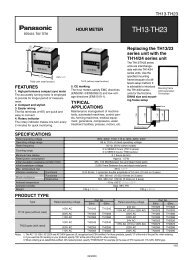
2. Counter voltage of DC relays<br />
If input is cut off in DC relays, a<br />
counter voltage is developed across<br />
the coil as a result of the collapse of<br />
the magnetic field. If the coil is used in<br />
a transistor circuit, the reverse voltage<br />
produced from the coil can cause a<br />
serious circuit malfunction.<br />
This counter voltage can be reduced<br />
considerably by connecting a capacitor<br />
or a diode in parallel with the coil.<br />
The level of reduction must be determined<br />
either by calculation if the coil<br />
data is available or by experiment.<br />
(1) Capacitor<br />
E<br />
SW<br />
Capacitor<br />
Relay Ry<br />
r<br />
(2) Diode<br />
SW<br />
Diode<br />
Relay Ry<br />
E<br />
3. Latching relay<br />
In order to assure proper operating<br />
regardless of changes in the ambient<br />
usage temperature and usage conditions,<br />
nominal operating voltage should be<br />
applied to the coil for more than 40 ms to<br />
set/reset the latching type relay.<br />
For Cautions for Use, see Relay Technical Information in catalog.<br />
7