6053/6055 Ethernet Communications Interface - Parker
6053/6055 Ethernet Communications Interface - Parker
6053/6055 Ethernet Communications Interface - Parker

You also want an ePaper? Increase the reach of your titles
YUMPU automatically turns print PDFs into web optimized ePapers that Google loves.
<strong>6053</strong>/<strong>6055</strong><br />
<strong>Ethernet</strong> <strong>Communications</strong><br />
<strong>Interface</strong><br />
Technical Manual<br />
HA468030U001 Issue 4<br />
Compatible with Version 1.x Software<br />
© Copyright 2011 <strong>Parker</strong> Hannifin Manufacturing Ltd<br />
All rights strictly reserved. No part of this document may be stored in a retrieval system, or transmitted in any<br />
form or by any means to persons not employed by a <strong>Parker</strong> Hannifin Manufacturing Limited without written<br />
permission from <strong>Parker</strong> Hannifin Manufacturing Limited. Although every effort has been taken to ensure the<br />
accuracy of this document it may be necessary, without notice, to make amendments or correct omissions.<br />
<strong>Parker</strong> Hannifin Manufacturing Limited cannot accept responsibility for damage, injury, or expenses resulting<br />
therefrom.<br />
WARRANTY<br />
Refer to <strong>Parker</strong> Hannifin Manufacturing Limited Terms and Conditions of Sale. These documents are available on<br />
request at www.parker.com.<br />
<strong>Parker</strong> Hannifin Manufacturing Limited reserves the right to change the content and product specification without<br />
notice.<br />
Cont.1
Safety Information<br />
!<br />
WARNING!<br />
During commissioning, remove the fuses (or trip the circuit breaker) on your 3-<br />
phase supply.<br />
Make sure the power is OFF, and that it cannot be switched on accidentally whilst you<br />
are working.<br />
REFER TO YOUR MAIN PRODUCT MANUAL FOR SPECIFIC SAFETY<br />
INFORMATION ABOUT THE DEVICE YOU ARE CONTROLLING<br />
IMPORTANT: Please read this information BEFORE installing the equipment.<br />
Intended Users<br />
This manual is to be made available to all persons who are required to install, configure or<br />
service equipment described herein, or any other associated operation.<br />
The information given is intended to highlight safety issues, EMC considerations, and to enable<br />
the user to obtain maximum benefit from the equipment.<br />
Application Area<br />
The equipment described is intended for industrial motor speed control.<br />
Personnel<br />
Installation, operation and maintenance of the equipment should be carried out by qualified<br />
personnel. A qualified person is someone who is technically competent and familiar with all<br />
safety information and established safety practices; with the installation process, operation and<br />
maintenance of this equipment; and with all the hazards involved.<br />
Safety<br />
All control and signal terminals are SELV, i.e. protected by double insulation.<br />
EMC<br />
In a domestic environment this product may cause radio interference in which case the user may<br />
be required to take adequate counter-measures.<br />
This equipment contains electrostatic discharge (ESD) sensitive parts. Observe static control<br />
precautions when handling, installing and servicing this product.<br />
Cont.2
Safety Information<br />
!<br />
CAUTION!<br />
At any time, there may be a loss of motor control and separate/independent application<br />
measures should be taken to ensure that such loss of motor control cannot present a safety<br />
hazard.<br />
RISK ASSESSMENT<br />
Under fault conditions, power loss or unintended operating conditions, the drive may not<br />
operate as intended. In particular:<br />
• Stored energy might not discharge to safe<br />
levels as quickly as suggested, and can still<br />
be present even though the drive appears to<br />
be switched off<br />
• The motor's direction of rotation might not<br />
be controlled<br />
• The motor speed might not be controlled<br />
• The motor might be energised<br />
A drive is a component within a drive system that may influence its operation or effects under<br />
a fault condition. Consideration must be given to:<br />
• Stored energy • Supply disconnects • Sequencing logic • Unintended<br />
operation<br />
Cont.3
Contents<br />
Contents<br />
Page<br />
ETHERNET TECHNOLOGY OPTION 1<br />
System Overview ............................................................................................. 1<br />
Product Features ........................................................................................................ 1<br />
Product Code and Contents........................................................................................ 1<br />
DSELite Requirements ................................................................................................. 1<br />
Hardware Installation ..................................................................................... 2<br />
Installing and Connecting the <strong>Ethernet</strong> Technology Option........................................... 2<br />
Connection Diagram.................................................................................................. 3<br />
Understanding the LED Indications................................................................. 4<br />
Initial Power-on Checks .............................................................................................. 4<br />
Configuring the Drive ...................................................................................... 5<br />
• The <strong>Ethernet</strong> MMI View............................................................................. 5<br />
• The Non-specific DSE-Lite & MMI View...................................................... 5<br />
• Parameter Descriptions ............................................................................ 6<br />
Commissioning the <strong>Ethernet</strong> Technology Option ............................................ 7<br />
Configuring the IP address ......................................................................................... 7<br />
• 590 + Point to Point I/O .......................................................................... 9<br />
• 690+ Point to Point I/O Connection ....................................................... 11<br />
Configuring the PLC/SCADA Supervisor .................................................................... 13<br />
• Modicon Momentum.............................................................................. 13<br />
• Allen Bradley ControlLogix ..................................................................... 15<br />
Appendix A: <strong>Ethernet</strong> Error Codes................................................................. 18<br />
Appendix B: Troubleshooting ........................................................................ 25<br />
• <strong>6053</strong>/<strong>6055</strong> <strong>Ethernet</strong> Technology Option Status LED ................................ 25<br />
Returning the Unit to <strong>Parker</strong> SSD Drives..................................................................... 26<br />
Disposal .................................................................................................................. 26<br />
Appendix C: External Control of the Drive .................................................... 27<br />
• 590+.................................................................................................... 27<br />
• 690+.................................................................................................... 30<br />
Appendix D Sample Configurations .............................................................. 34<br />
Cont.4
ETHERNET TECHNOLOGY OPTION<br />
System Overview<br />
1<br />
Product Features<br />
• Compact: 127mm (5) H x 76.2mm (3) W x 25.4mm (1) D - (inches)<br />
• Plug-in installation to drive<br />
• Suitable for use with drive models:<br />
590+ software version >7.1; 690+ software version >4.7<br />
• Connection using serial cable (shielded twisted pair)<br />
• LED’s to indicate board and communications status<br />
• 10 / 100 M bits/s<br />
• Default Slave Address allows switch selectable I/P address.<br />
• Slave Address can be set using MicroSoft Internet Explorer.<br />
• Supported protocols ModBus/TCP and <strong>Ethernet</strong>/IP<br />
Product Code and Contents<br />
The <strong>Parker</strong> SSD Drives’ product is fully identified using an alphanumeric code which records<br />
how the product was assembled, and its various settings when despatched from the factory.<br />
The Technology Option can be supplied with the drive product, or supplied separately:<br />
Product<br />
Product Code when supplied with the Drive Product Code when supplied separately<br />
690+B 690-xxxxxxxx-xxxxxx-xxxE<br />
US Model No. & Legacy Code <strong>6053</strong>-ENET-00 - plug-in Technology Box<br />
690PB/xxxx/xxx/x/x/xxxx/xx/x/ENET/x/x<br />
690+C-J 690-xxxxxxxx-xxxxxx-xxxE<br />
US Model No. & Legacy Code <strong>6055</strong>-ENET-00 - plug-in Technology Box<br />
690Px/xxxx/xxx/x/x/xxxx/xx/x/ENET/x/x<br />
590+ 590P-xxxxxxxx-xxx-xxxE<br />
US Model No. & Legacy Code <strong>6055</strong>-ENET-00 - plug-in Technology Box<br />
590P/xxxx/xxx/xxxx/xx/xxx/ENET/xxx/xxx<br />
591P<br />
DSELite Requirements<br />
All versions<br />
591P-xxxxxxxx-xxx-xxxE<br />
US Model No. & Legacy Code <strong>6055</strong>-ENET-00 - plug-in Technology Box<br />
591P/xxxx/xxx/xxxx/xx/xxx/ENET/xxx/xxx<br />
<strong>6053</strong>/<strong>6055</strong> <strong>Ethernet</strong> <strong>Communications</strong> <strong>Interface</strong>
2<br />
Hardware Installation<br />
Installing and Connecting the <strong>Ethernet</strong> Technology Option<br />
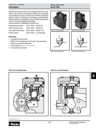
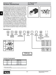
<strong>6053</strong>-ENET-00 TECHBOX <strong>6055</strong>-ENET-00 TECHBOX<br />
Figure 1. The <strong>Ethernet</strong> Technology Options<br />
WARNING!<br />
Prior to starting work ensure all sources of power are isolated.<br />
The <strong>Ethernet</strong> Technology Option plugs into the drive in the slot provided.<br />
Frame B<br />
Fit the Technology Option in place of the Keypad. Connect the supplied yellow/green wire<br />
between the Technology Option's metal case and one of the chassis earth pillars. Fit a 6052<br />
Remote Mounting Kit to use the keypad with the drive while the Technology Option is installed.<br />
Refer to Figure 2.<br />
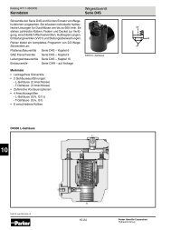
Frames C - J<br />
Fit the Technology Option in the right-hand "Comms Option" position. Refer to Figure 3.<br />
Technology<br />
Box<br />
screen connections<br />
Technology<br />
Box<br />
Captive Screw<br />
Figure 2. 690+ Frame B<br />
Figure 3. 690+ frames C-J, 605C, 590+,<br />
590+DRV (590+ 15A unit illustrated)<br />
<strong>6053</strong>/<strong>6055</strong> <strong>Ethernet</strong> <strong>Communications</strong> <strong>Interface</strong>
Connection Diagram<br />
3<br />
WARNING!<br />
Before installing, ensure that the drive wiring is electrically isolated and cannot be<br />
made "live" unintentionally by other personnel.<br />
Wait 5 minutes after disconnecting power before working on any part of the system<br />
or removing the covers from the drive.<br />
Connection to the drive(s) from a PC, or PLC for example, is made using a cable fitted with<br />
standard RJ45 connectors at both ends. The cable plugs into the PLC, for example, and into the<br />
socket on the <strong>Ethernet</strong> techbox.<br />
Note:<br />
When connecting to one drive direct from PC/PLC, you must use a crossover cable.<br />
PLC<br />
PLC<br />
Switch/Hub<br />
RJ45 (Standard) Pin Details<br />
Pin Signal<br />
1 TD+<br />
2 TD-<br />
3 RD+<br />
4 Termination<br />
5 Termination<br />
6 RD-<br />
7 Termination<br />
8 Termination<br />
Cable Specifications<br />
Cable Type Maximum Node-to-Node Distance<br />
(m)<br />
CAT5 100<br />
CAT5E 100<br />
<strong>6053</strong>/<strong>6055</strong> <strong>Ethernet</strong> <strong>Communications</strong> <strong>Interface</strong>
4<br />
Understanding the LED Indications<br />
Network LED<br />
Indicates the state of the connected<br />
network.<br />
The states indicated are those produced<br />
by the NET STATE parameter of the TEC<br />
OPTION function block.<br />
Module LED<br />
Indicates the set-up state of the<br />
Technology Option.<br />
The states indicated are those produced<br />
by the FAULT parameter of the<br />
TEC OPTION function block.<br />
Network LED<br />
Indication<br />
NET STATE<br />
Parameter<br />
Module LED<br />
Indication<br />
FAULT Parameter<br />
ON<br />
0 CONNECTED<br />
ON<br />
0 NONE<br />
LONG FLASH<br />
1 reserved<br />
LONG FLASH<br />
1 PARAMETER<br />
FLASH<br />
2 reserved<br />
FLASH<br />
2 TYPE MISMATCH<br />
SHORT FLASH<br />
3 NOT CONNECTED<br />
SHORT FLASH<br />
3 SELF TEST<br />
OFF<br />
4 DISABLED<br />
OFF<br />
4 HARDWARE<br />
5 INITIALISING<br />
Figure 4. LED Status Indication<br />
Note: The NETWORK LED is always in the OFF State when the MODULE LED is not ON.<br />
Initial Power-on Checks<br />
With the TechBox correctly fitted and configured the MODULE LED will be ON continuously<br />
and the NETWORK LED will flash to indicate the Not Connected state.<br />
<strong>6053</strong>/<strong>6055</strong> <strong>Ethernet</strong> <strong>Communications</strong> <strong>Interface</strong>
Configuring the Drive<br />
5<br />
Begin by configuring the drive to accept the Technology Option. Use the keypad (MMI), or<br />
DSE Lite to configure the TEC OPTION function block parameters inside the drive before<br />
commissioning the <strong>Ethernet</strong> technology option.<br />
The parameter names and functions in this function block are inter-dependent and will change<br />
with different parameter values and various Options that can be fitted.<br />
Fit the <strong>Ethernet</strong> option to the drive:<br />
• Navigate to the VIEW LEVEL parameter and select<br />
ADVANCED. This allows you to view the SETUP<br />
PARAMETERS menu.<br />
690+MMI<br />
Menu Map<br />
1 QUICK SETUP<br />
VIEW LEVEL<br />
• In the SETUP PARAMETERS menu, navigate to the TEC OPTION menu and set the<br />
TYPE parameter to "ETHERNET".<br />
Note:<br />
When using the MMI, remember to save the set-up via the Parameter Save or Config<br />
Save menu.<br />
The <strong>Ethernet</strong> MMI View<br />
With the <strong>Ethernet</strong> option correctly installed, the TEC OPTION<br />
function block will contain the following parameter names when<br />
viewed using the MMI.<br />
Tec Option<br />
FAULT [756] – NONE<br />
VERSION [757] – 0103<br />
NET STATE [758] – NOT CONNECTED<br />
UNUSED 5 [759] – 0000<br />
ETHERNET – [750] TYPE –<br />
FALSE – [751] BYTE SWAP –<br />
0 – [752] UNUSED 1 –<br />
0 – [753] UNUSED 2 –<br />
0 – [754] UNUSED 3 –<br />
0 – [755] UNUSED 4 –<br />
<strong>Ethernet</strong> MMI View<br />
The Non-specific DSE-Lite & MMI View<br />
This is how the TEC OPTION function block looks when viewed<br />
using DSE-Lite.<br />
The MMI also displays these non-specific parameter names when<br />
the <strong>Ethernet</strong> option is not yet installed into the drive, or an<br />
incorrect TYPE is selected for the fitted Option.<br />
Tec Option<br />
FAULT [756] – NONE<br />
VERSION [757] – 0000<br />
OUTPUT 1 [758] – 0000<br />
OUTPUT 2 [759] – 0000<br />
ETHERNET – [750] TYPE –<br />
0 – [751] INPUT 1 –<br />
0 – [752] INPUT 2 –<br />
0 – [753] INPUT 3 –<br />
0 – [754] INPUT 4 –<br />
0 – [755] INPUT 5 –<br />
Non-specific DSE-Lite & MMI view<br />
690+ MMI<br />
Menu Map<br />
1 SETUP PARAMETERS<br />
2 COMMUNICATIONS<br />
3 TEC OPTION<br />
TYPE<br />
BYTE SWAP<br />
UNUSED 1<br />
UNUSED 2<br />
UNUSED 3<br />
UNUSED 4<br />
FAULT<br />
VERSION<br />
NET STATE<br />
UNUSED 5<br />
690+ MMI<br />
Menu Map<br />
1 SETUP PARAMETERS<br />
2 COMMUNICATIONS<br />
3 TEC OPTION<br />
TYPE<br />
INPUT 1<br />
INPUT 2<br />
INPUT 3<br />
INPUT 4<br />
INPUT 5<br />
FAULT<br />
VERSION<br />
OUTPUT 1<br />
OUTPUT 2<br />
<strong>6053</strong>/<strong>6055</strong> <strong>Ethernet</strong> <strong>Communications</strong> <strong>Interface</strong>
6<br />
Parameter Descriptions<br />
TYPE<br />
Range: Enumerated - see below<br />
Selects the type of Technology Option. Select ETHERNET for this parameter.<br />
Enumerated Value : Technology Option<br />
0 : NONE<br />
1 : RS485<br />
2 : PROFIBUS DP<br />
3 : LINK<br />
4 : DEVICENET<br />
5 : CANOPEN<br />
6 : LONWORKS<br />
7 : CONTROLNET<br />
8 : MODBUS PLUS<br />
9 : ETHERNET<br />
BYTE SWAP<br />
Range: FALSE / TRUE<br />
When this parameter to set TRUE, the byte order is swapped for each 16-bit value<br />
being transferred. This typically is required when using the ETHERNET/IP protocol<br />
connected to an Allen Bradley PLC.<br />
When using MODBUS TCP/IP protocol, set this parameter to FALSE.<br />
UNUSED 1-4<br />
Reserved for future use.<br />
FAULT<br />
Range: Enumerated - see below<br />
The fault state of the Technology Option.<br />
Enumerated Value : FAULT state<br />
0 : NONE no faults<br />
1 : PARAMETER parameter out-of-range<br />
2 : TYPE MISMATCH TYPE parameter not set to ETHERNET<br />
3 : SELF TEST hardware fault - internal<br />
4 : HARDWARE hardware fault - external<br />
5 : MISSING no option fitted<br />
VERSION<br />
Range: 0000 to FFFF<br />
The version of the Technology Option card. If no option is fitted then the version is<br />
reset to zero. For example, 0103 is version 1.3.<br />
NET STATE<br />
Range: Enumerated - see below<br />
State of the <strong>Ethernet</strong> network connection.<br />
Enumerated Value : NET STATE<br />
0 : CONNECTED<br />
1 : NOT CONNECTED<br />
2 : DISABLED<br />
UNUSED 5<br />
Reserved for future use.<br />
Note: You can use the functionality of any of the drive's internal Function Blocks with the<br />
Technology Option. In some cases, the 590+ drive may require you to use the<br />
MiniLINK function block to achieve proper triggering of other function blocks.<br />
IMPORTANT: When using DSE Lite, install the configuration into the drive through the P3 port<br />
(RS232 configuration port) using the Command/Install pull-down menu. The<br />
configuration is saved directly to the Drive’s internal memory. For more details on<br />
installing a configuration, refer to the DSE Lite Instruction Manual (HA471486U001).<br />
<strong>6053</strong>/<strong>6055</strong> <strong>Ethernet</strong> <strong>Communications</strong> <strong>Interface</strong>
Commissioning the <strong>Ethernet</strong> Technology Option<br />
7<br />
Configuring the IP address<br />
When the Technology Option is shipped from the factory, all the switches are in the OFF<br />
position. The Technology Option will read the switches during initialization. The position<br />
of these switches determine how the IP address can be configured.<br />
The IP address can be configured using one of three methods:<br />
1 Configure IP Address using DIL Switches<br />
If the switches are set to a non-zero value the address will come from the DIL switches.<br />
The Subnet mask and Gateway addresses are fixed to the following values:<br />
Subnet mask: 255.255.255.0<br />
Gateway address: 0.0.0.0<br />
The eight position DIL switch represents the binary<br />
value of the last byte of the IP address:<br />
Example IP address: 192.168.0.20 where the<br />
switches are set to 00010100 (decimal 20)<br />
1 2 3 4 5 6 7 8<br />
ON<br />
(MSB)<br />
(LSB)<br />
Figure 3. IP Address Selector Switch<br />
2 Configure IP Address using<br />
Internet Explorer<br />
Note: The IP address can be configured via the intranet using Internet Explorer (version<br />
5.5 or higher). It is possible to use other web browsers, but for our example we will<br />
be using Internet Explorer version 6.<br />
If all switches are in the OFF position (zero value), the IP address will be read from the<br />
flash memory that is configured with Internet Explorer.<br />
1. Set a temporary IP address using the DIL switches. This provides an IP address on the<br />
Technology Option. For example, set IP address 192.168.0.20. Refer to Figure 3.<br />
2. Temporarily change the computer’s Internet protocol properties to gain access to the<br />
intranet that is used with Technology Option. This example will use IP address<br />
192.168.0.1. Refer to Figure 4.<br />
Figure 4. Internet Protocol Properties<br />
<strong>6053</strong>/<strong>6055</strong> <strong>Ethernet</strong> <strong>Communications</strong> <strong>Interface</strong>
8<br />
3. Launch Internet Explorer.<br />
4. Go to the intranet address that was set by the DIL switches. The screen shown in<br />
Figure 5 will be displayed. Input the desired IP address and Store Configuration.<br />
Note: The Gateway address will need to be set if access from another subnetwork<br />
is required.<br />
Figure 5. Configuration Web Page<br />
5. Restore all the DIL switches to the OFF position (zero value).<br />
The flash memory in the Technology Box is now programmed. When the Technology Box<br />
is initialised on the next power-up cycle, the IP address will come from flash memory,<br />
provided that the DIL switches are set to the OFF position (zero value).<br />
3 Using the Address Resolution Protocol (ARP)<br />
The IP address can be changed during runtime using the ARP command from a PC. The<br />
new IP address will be stored in the FLASH.<br />
Below is an example on how to change the IP address from a MS DOS window:<br />
arp -s <br />
ping <br />
arp -d <br />
The arp -s command will store the IP and MAC addresses in the PC’s ARP table. When the<br />
ping command is executed, the PC sends this information to the module using the MAC<br />
address. The module detects that it was addressed with the correct MAC address and adopts<br />
the IP address sent by the PC. (The arp -d command is optional, but it removes the static<br />
route from the PC ARP table).<br />
This method can be used to reconfigure modules that have already been configured, or even<br />
to reconfigure modules outside the host’s subnet.<br />
The MAC address is printed on a label on the bottom side of the module.<br />
Note: As the Arp command automatically configures the subnet mask to 255.255.255.0,<br />
the first three bytes of the IP address must be the same as for the PC executing the<br />
command.<br />
Example:<br />
PC - 10.10.12.67<br />
Module- 10.10.12.x (Where x is a value between 1 and 254)<br />
<strong>6053</strong>/<strong>6055</strong> <strong>Ethernet</strong> <strong>Communications</strong> <strong>Interface</strong>
590 + Point to Point I/O<br />
Point-to-Point I/O connections enable several parameter values to be passed in one transaction.<br />
The connections are predefined sets of parameters.<br />
<strong>Parker</strong> SSD Drives has predefined an assembly object. They are defined on the following<br />
pages. These sets are specific to <strong>Parker</strong> SSD Drives products.<br />
The following table provides a summary of the bytes that are transferred.<br />
Read/Write Number of bytes transferred Drives applicable<br />
Read 20 590+<br />
Write 20 590+<br />
9<br />
Access: Read from Technology Option<br />
590+<br />
Bytes<br />
Description<br />
Drive Tag Range<br />
Number<br />
0, 1 Sequence Status 537 0000 - FFFF<br />
2 Bit-field:<br />
Bit Number:<br />
0 User Defined Logic 1 (PNO 112) Indirect 312 1 Binary<br />
1 User Defined Logic 2 (PNO 113) Indirect 313 1 Binary<br />
2 User Defined Logic 3 (PNO 114) Indirect 314 1 Binary<br />
3 User Defined Logic 4 (PNO 115) Indirect 315 1 Binary<br />
4 User Defined Logic 5 (PNO 116) Indirect 316 1 Binary<br />
5 User Defined Logic 6 (PNO 117) Indirect 317 1 Binary<br />
6 User Defined Logic 7 (PNO 118) Indirect 318 1 Binary<br />
7 User Defined Logic 8 (PNO 119) Indirect 319 1 Binary<br />
3 Reserved<br />
4, 5 User Defined Value 1 (PNO 120) Indirect 320 1 Tag Dependent<br />
6, 7 User Defined Value 2 (PNO 121) Indirect 321 1 Tag Dependent<br />
8, 9 User Defined Value 3 (PNO 122) Indirect 322 1 Tag Dependent<br />
10, 11 User Defined Value 4 (PNO 123) Indirect 323 1 Tag Dependent<br />
12, 13 User Defined Value 5 (PNO 124) Indirect 324 1 Tag Dependent<br />
14, 15 User Defined Value 6 (PNO 125) Indirect 325 1 Tag Dependent<br />
16, 17 User Defined Value 7 (PNO 126) Indirect 326 1 Tag Dependent<br />
18, 19 User Defined Value 8 (PNO 127) Indirect 327 1 Tag Dependent<br />
1. Tags 312 to 323 are indirect parameters. Their values are destination tag numbers for<br />
<strong>Ethernet</strong> data. For example, if the value of Tag 320 (PNO 120) is 2, then the value of User<br />
Defined Value 1 (bytes 4,5) will be read from Tag 2 (RAMP ACCEL TIME). If some of the<br />
User Defined parameters are not required, the corresponding destination tag numbers<br />
should be set to 0.<br />
2. Refer to Appendix C for Sequence Status and Remote Sequence details.<br />
<strong>6053</strong>/<strong>6055</strong> <strong>Ethernet</strong> <strong>Communications</strong> <strong>Interface</strong>
10<br />
Access: Write to Technology Option<br />
Bytes<br />
Description<br />
590+<br />
Drive Tag<br />
Number<br />
Range<br />
0, 1 Remote Sequence 536 1 0000 to FFFF<br />
2 Bit-field:<br />
Bit Number<br />
0 User Defined Logic 1<br />
(miniLINK LOGIC 1)<br />
1 User Defined Logic 2<br />
(miniLINK LOGIC 2)<br />
2 User Defined Logic 3<br />
(miniLINK LOGIC 3)<br />
3 User Defined Logic 4<br />
(miniLINK LOGIC 4)<br />
4 User Defined Logic 5<br />
(miniLINK LOGIC 5)<br />
5 User Defined Logic 6<br />
(miniLINK LOGIC 6)<br />
6 User Defined Logic 7<br />
(miniLINK LOGIC 7)<br />
7 User Defined Logic 8<br />
(miniLINK LOGIC 8)<br />
3 Reserved<br />
4, 5 User Defined Value 1 (miniLINK<br />
VALUE 1)<br />
6, 7 User Defined Value 2 (miniLINK<br />
VALUE 2)<br />
8, 9 User Defined Value 3 (miniLINK<br />
VALUE 3)<br />
10, 11 User Defined Value 4 (miniLINK<br />
VALUE 4)<br />
12, 13 User Defined Value 5 (miniLINK<br />
VALUE 5)<br />
14, 15 User Defined Value 6 (miniLINK<br />
VALUE 6)<br />
16, 17 User Defined Value 7 (miniLINK<br />
VALUE 7)<br />
18, 19 User Defined Value 8 (miniLINK<br />
VALUE 8)<br />
346 Binary<br />
347 Binary<br />
348 Binary<br />
349 Binary<br />
350 Binary<br />
351 Binary<br />
352 Binary<br />
353 Binary<br />
339 ± 100%<br />
340 ± 100%<br />
341 ± 100%<br />
342 ± 100%<br />
343 ± 100%<br />
344 ± 100%<br />
345 ± 100%<br />
379 ± 100%<br />
1. Tag 536 functions only when REM SEQ ENABLE (Tag 535) is TRUE.<br />
2. Refer to Appendix C for Sequence Status and Remote Sequence details.<br />
<strong>6053</strong>/<strong>6055</strong> <strong>Ethernet</strong> <strong>Communications</strong> <strong>Interface</strong>
11<br />
690+ Point to Point I/O Connection<br />
Point-to-Point I/O connections enable several parameter values to be passed in one transaction.<br />
Lists of parameters to be written to the drive and read from it are predefined.<br />
TechBox parameters are detailed below; the parameters are specific to <strong>Parker</strong> SSD Drives<br />
products. These indicate the drive tag number that is accessed in each case.<br />
The following table provides a summary of the bytes that are transferred.<br />
Read/Write Number of bytes transferred Drives applicable<br />
Read 36 690+<br />
Write 36 690+<br />
Lists of parameters to be written to and from the drive are accessed through Preset Block 5,<br />
Preset Block 6, Preset blocks 7, Preset 8, Demux block 1 and Mux block 1. The user is able to<br />
link these function blocks to achieve the desired operation. The following tables provide a<br />
description of the parameters that are accessed.<br />
Refer to Appendix C for Comms Status and Comms Command details.<br />
Access: Read from TechBox<br />
690+<br />
Bytes<br />
Description<br />
Drive Tag Range<br />
Number<br />
0,1 Comms Status 272 0000 to FFFF<br />
2,3 Mux 1 Output 598 0000 to FFFF<br />
4,5 Preset 7::Input 0 543 -327.68 to 327.67<br />
6,7 Preset 7::Input 1 544 -327.68 to 327.67<br />
8,9 Preset 7::Input 2 545 -327.68 to 327.67<br />
10,11 Preset 7::Input 3 546 -327.68 to 327.67<br />
12,13 Preset 7::Input 4 547 -327.68 to 327.67<br />
14,15 Preset 7::Input 5 548 -327.68 to 327.67<br />
16,17 Preset 7::Input 6 549 -327.68 to 327.67<br />
18,19 Preset 7::Input 7 550 -327.68 to 327.67<br />
20,21 Preset 5::Input 0 521 -327.68 to 327.67<br />
22,23 Preset 5::Input 1 522 -327.68 to 327.67<br />
24,25 Preset 5::Input 2 523 -327.68 to 327.67<br />
26,27 Preset 5::Input 3 524 -327.68 to 327.67<br />
28,29 Preset 5::Input 4 525 -327.68 to 327.67<br />
30,31 Preset 5::Input 5 526 -327.68 to 327.67<br />
32,33 Preset 5::Input 6 527 -327.68 to 327.67<br />
34,35 Preset 5::Input 7 528 -327.68 to 327.67<br />
Refer to Appendix C for Comms Status and Comms Command details.<br />
<strong>6053</strong>/<strong>6055</strong> <strong>Ethernet</strong> <strong>Communications</strong> <strong>Interface</strong>
12<br />
Access: Write to TechBox<br />
Bytes<br />
Description<br />
690+<br />
Drive Tag<br />
Number<br />
Range<br />
0,1 Comms Command 271 0000 to FFFF<br />
2,3 Demux 1::Input 599 0000 to FFFF<br />
4,5 Preset 8::Input 0 554 -327.68 to 327.67<br />
6,7 Preset 8::Input 1 555 -327.68 to 327.67<br />
8,9 Preset 8::Input 2 556 -327.68 to 327.67<br />
10,11 Preset 8::Input 3 557 -327.68 to 327.67<br />
12,13 Preset 8::Input 4 558 -327.68 to 327.67<br />
14,15 Preset 8::Input 5 559 -327.68 to 327.67<br />
16,17 Preset 8::Input 6 560 -327.68 to 327.67<br />
18,19 Preset 8::Input 7 561 -327.68 to 327.67<br />
20,21 Preset 6::Input 0 532 -327.68 to 327.67<br />
22,23 Preset 6::Input 1 533 -327.68 to 327.67<br />
24,25 Preset 6::Input 2 534 -327.68 to 327.67<br />
26,27 Preset 6::Input 3 535 -327.68 to 327.67<br />
28,29 Preset 6::Input 4 536 -327.68 to 327.67<br />
30,31 Preset 6::Input 5 537 -327.68 to 327.67<br />
32,33 Preset 6::Input 6 538 -327.68 to 327.67<br />
34,35 Preset 6::Input 7 539 -327.68 to 327.67<br />
Refer to Appendix C for Comms Status and Comms Command details.<br />
Network Break Strategy<br />
You can select what the “Write to TechBox” parameters are set to when the network is<br />
disconnected.<br />
Set the behaviour using the COMMS TIMEOUT parameter in the COMMS CONTROL<br />
Function Block. Also refer to the 690+ Software Product Manual.<br />
COMMS TIMEOUT = 0 Secs<br />
COMMS TIMEOUT > 0 Secs<br />
When the connection is broken, all parameters being<br />
written to the Inverter from the PLC will be set to zero.<br />
The Inverter will not Trip.<br />
When the connection is broken, all parameters being<br />
written to the Inverter from the PLC will freeze at their<br />
last value. After the time specified by the COMMS<br />
TIMEOUT parameter has elapsed, the Inverter will Trip<br />
(COMMS TIMEOUT Trip).<br />
<strong>6053</strong>/<strong>6055</strong> <strong>Ethernet</strong> <strong>Communications</strong> <strong>Interface</strong>
Configuring the PLC/SCADA Supervisor<br />
This chapter contains examples for configuring a Modicon and an Allen-Bradley PLC. The<br />
<strong>Ethernet</strong> Technology Box supports the ModBus/TCP protocol and the <strong>Ethernet</strong>/IP protocol.<br />
Modicon Momentum<br />
1. Start a new program and select<br />
the PLC processor and chassis<br />
type used in your project. Our<br />
example uses an M1 980-20<br />
Momentum PLC. Stay offline<br />
until you are ready to download<br />
the program.<br />
2. Place an MSTR block in the<br />
ladder logic. MSTR blocks move<br />
data from the PLC data table to<br />
the drive or from the drive to the<br />
PLC data table. Two MSTR<br />
blocks are necessary for a Read<br />
and Write operation.<br />
3. Right click over the MSTR block.<br />
This will access the Register<br />
Editor. Use the Register Editor to<br />
configure the block. The MSTR<br />
block has two types of<br />
operations: Read or Write. The<br />
first register defines the type of<br />
operation. In our case address<br />
40100 is used for write command<br />
and address 40200 is used for<br />
read command. A value of 1 in<br />
Figure 6. PLC Ladder Logic<br />
the data column defines a Write<br />
showing MSTR Blocks<br />
operation. A value of 2 in the data column defines a Read operation.<br />
13<br />
Figure 7. Read Registers<br />
<strong>6053</strong>/<strong>6055</strong> <strong>Ethernet</strong> <strong>Communications</strong> <strong>Interface</strong>
14<br />
Figure 8 Write Registers<br />
4. The second register contains the error status. Refer to Appendix A for a list of the<br />
error codes. The PLC software also has help files that contain a list of error codes.<br />
5. The third register defines the data length (address 40102 or address 40202). The value<br />
in the data column depends on which parameter set that has been selected in the drive.<br />
The value can be smaller than or equal to the selected parameter set.<br />
6. The fourth register defines the Read and Write locations of the data in the PLC (address<br />
40103 or address 40203). For a Read function, this value is set to 1, and for a Write<br />
function this value is set to 1025.<br />
7. Registers 5, 6, 7 and 8 define the IP address on the <strong>Ethernet</strong> network (address 40104 or<br />
address 40204). Our example shows the data registers starting at locations 40150 and<br />
40250.<br />
8. When using the ModBus/TCP protocol the TechBox needs to be programmed with the<br />
“BYTE SWAP” FALSE. This applies to Modicon products and other manufactures<br />
using the ModBus/TCP protocol.<br />
<strong>6053</strong>/<strong>6055</strong> <strong>Ethernet</strong> <strong>Communications</strong> <strong>Interface</strong>
15<br />
Allen Bradley ControlLogix<br />
9. Start a new program and select the PLC processor and chassis type that is used in your<br />
project. Our example uses a 1756-L55A processor and 1756-A7/B rack. Remain Offline<br />
until you are ready to download the program.<br />
10. Using the I/O Configuration insert the <strong>Ethernet</strong> interface that will be installed. Right click<br />
on the I/O Configuration, select New Module. Our example uses 1756-ENBT/A. Input the<br />
desired IP address and slot in the PLC. Refer to Figures 9 and 10.<br />
Controller <strong>Parker</strong>_SSD_<strong>Ethernet</strong>_TechBox<br />
Figure 9. <strong>Ethernet</strong> <strong>Interface</strong> Selection<br />
Controller <strong>Parker</strong>_SSD_<strong>Ethernet</strong>_TechBox<br />
Figure 10. <strong>Ethernet</strong> <strong>Interface</strong> Setup<br />
<strong>6053</strong>/<strong>6055</strong> <strong>Ethernet</strong> <strong>Communications</strong> <strong>Interface</strong>
16<br />
11. Right click on the <strong>Ethernet</strong> <strong>Interface</strong> Module, select New Module. This screen will allow<br />
the selection of the Generic <strong>Ethernet</strong> Module. Refer to Figure 11.<br />
Controller <strong>Parker</strong>_SSD_<strong>Ethernet</strong>_TechBox<br />
Figure 11. Generic <strong>Ethernet</strong> Module Select<br />
12. Input the desired module name and IP address. The Comms format will be DATA Int. (16<br />
bit). The Input Assembly Instance is 100 and the Output Assembly Instance is 150. The<br />
data size for the 590 Plus is 10 words and the data size for the 690 Plus is 18 words. Refer<br />
to Figure 12.<br />
13. Click on Next to change the Requested Packet Interval (RPI). The default value of 10ms<br />
should be sufficient. If The RPI is set below 5ms unreliable communications will be<br />
experienced. Refer to Figure 12.<br />
Figure 12. Generic <strong>Ethernet</strong> Module Setup<br />
<strong>6053</strong>/<strong>6055</strong> <strong>Ethernet</strong> <strong>Communications</strong> <strong>Interface</strong>
17<br />
14. When completed with the setup of the Generic <strong>Ethernet</strong> Module it can be downloaded to<br />
the PLC. For testing purposes it is not necessary to program Ladder Logic in the PLC. The<br />
data can be accessed and monitored via Controller Tags. Refer to Figure 13.<br />
<strong>Parker</strong>_SSD_<strong>Ethernet</strong>_TechBox<br />
Figure 13. Controller Tags<br />
15. When using the <strong>Ethernet</strong>/IP protocol the Technology Box needs to be programmed with the<br />
“BYTE SWAP” TRUE. This applies to Allen Bradley products and other manufactures<br />
using the <strong>Ethernet</strong>/IP protocol.<br />
<strong>6053</strong>/<strong>6055</strong> <strong>Ethernet</strong> <strong>Communications</strong> <strong>Interface</strong>
18<br />
Appendix A: <strong>Ethernet</strong> Error Codes<br />
Error Codes (Modbus Plus & SY/MAX <strong>Ethernet</strong>)<br />
Error Status Register: 4xxxx + 1 (HEX)<br />
Error Coding: Mmss where M = major code, m = minor code, ss = sub code<br />
n<br />
n<br />
n<br />
n<br />
n<br />
n<br />
n<br />
16#1001: User initiated abort.<br />
16#20ss: Invalid command errors.<br />
16#30ss: Modbus slave exception response.<br />
16#4001: Inconsistent Modbus slave response.<br />
16#5001: Inconsistent network response.<br />
16#6mss: Routing failure.<br />
16#F001: Selected S985 option is not present.<br />
Invalid Command Errors<br />
Error Status Register: 4xxxx+1 (HEX)<br />
Error Coding: Mmss where M = major code, m = minor code, ss = sub code<br />
n<br />
n<br />
n<br />
n<br />
n<br />
n<br />
n<br />
n<br />
n<br />
2001: Invalid operation type.<br />
2002: User parameter changed.<br />
2003: Invalid length.<br />
2004: Invalid offset.<br />
2005: Invalid length + offset.<br />
2006: Invalid SDDA (Slave Device Data Area).<br />
2007: Invalid SDNA (Slave Device Network Address).<br />
2008: Invalid SDNR (Slave Device Network Routing).<br />
2009: Invalid route ( = own address).<br />
n<br />
n<br />
n<br />
n<br />
200A: Global read request > available.<br />
200B: Peer Cop conflict on write/read global data.<br />
200C: Bad pattern for change address request.<br />
200D: Bad address for change address request.<br />
<strong>Ethernet</strong>/Modbus Slave Exception Response<br />
Error Status Register: 4xxxx+1 (HEX)<br />
Error Coding: Mmss where M = major code, m = minor code, ss = sub code<br />
n<br />
n<br />
n<br />
n<br />
n<br />
n<br />
n<br />
3001: Illegal function request (not available in slave).<br />
3002: Illegal data address (not configured in slave).<br />
3003: Illegal data value (Read/Write data not valid).<br />
3004: Not used (unknown error).<br />
3005: Slave accepted long duration program command.<br />
3006: Requested function cannot be performed due to long command in progress.<br />
3007: Slave rejected long program command.<br />
<strong>6053</strong>/<strong>6055</strong> <strong>Ethernet</strong> <strong>Communications</strong> <strong>Interface</strong>
Routing Failures<br />
Error Status Register: 4xxxx + 1 (HEX)<br />
Error Coding: Mmss where M = major code, m = minor code, ss = sub code<br />
Routing failure error code: 6mjj<br />
19<br />
n<br />
n<br />
n<br />
n<br />
n<br />
n<br />
n<br />
n<br />
n<br />
n<br />
6m01: No response.<br />
6m02: Program access denied.<br />
6m03: Node is offline and unable to communicate.<br />
6m04: Exception response received.<br />
6m05: Route node data paths busy.<br />
6m06: Slave device down.<br />
6m07: Bad destination address.<br />
6m08: Invalid node type in routing.<br />
6m10: Slave rejected the Modbus command.<br />
6m20: Slave forgot initiated translation.<br />
n<br />
n<br />
6m40: Unexpected master output path received.<br />
6m80: Unexpected response received.<br />
Note: m = index to location in the routing information where routing problem was discovered.<br />
0 = local network station<br />
1 = first device in route<br />
2 = second device in route, etc.<br />
<strong>Ethernet</strong>/Modbus Slave Exception Response<br />
Error Status Register: 4xxxx+1 (HEX)<br />
Error Coding: Mmss where M = major code, m = minor code, ss = sub code<br />
n 3001: Illegal function request (not available in slave).<br />
n 3002: Illegal data address (not configured in slave).<br />
n 3003: Illegal data value (Read/Write data not valid).<br />
n 3004: Not used (unknown error).<br />
n 3005: Slave accepted long duration program command.<br />
n 3006: Requested function cannot be performed due to long command in progress.<br />
n 3007: Slave rejected long program command.<br />
<strong>6053</strong>/<strong>6055</strong> <strong>Ethernet</strong> <strong>Communications</strong> <strong>Interface</strong>
20<br />
Error Codes (Allen Bradley Communication Modules)<br />
Module Faults: 16#0001 - 16#00ff<br />
Code: String: Explanation and Possible Causes/Solutions:<br />
16#0004 Connection Request<br />
Error: Bad Segment<br />
16#0005 Connection Request<br />
Error: Bad Class<br />
16#0008 Service Request Error:<br />
Unsupported Service<br />
16#0009 Module Configuration<br />
Invalid: parameter<br />
error.<br />
Note: Additional Error<br />
Information for this<br />
fault will be displayed<br />
as a hex code on the<br />
Connection Tab.<br />
16#000c Service Request Error:<br />
Invalid mode/state for<br />
service request<br />
16#0013 Module Configuration<br />
Invalid: data size too<br />
small.<br />
16#0015 Module Configuration<br />
Invalid: data size too<br />
large.<br />
16#0016 Service Request Error:<br />
Unknown Object<br />
The controller is attempting to make a connection to the module and has<br />
received an error.<br />
The controller is attempting to make a connection to the module and has<br />
received an error<br />
The controller is attempting to request a service from the module and<br />
has received an error.<br />
The configuration for the module is invalid.<br />
The module configuration may have been changed in the Tag Monitor<br />
or programmatically. Verify that the configuration is valid by using the<br />
module configuration software to validate your configuration.<br />
The controller is attempting to request a service from the module and<br />
has received an error.Ensure that the module is not faulted. §<br />
For a Discrete I/O module, this indicates that the module still has limited<br />
communications, but has a Major Fault or is currently being Flash<br />
Updated. Refer to the Module Info tab to determine the exact cause.<br />
The configuration for the module is invalid – not enough configuration<br />
data was sent.<br />
The configuration for the module is invalid – too much configuration<br />
data was sent.<br />
The controller is attempting to request a service from the module and<br />
has received an error.<br />
Module Faults: 16#0100 - 16#01ff<br />
Code: String: Explanation and Possible Causes/Solutions:<br />
16#0100 Connection Request<br />
Error: Module in Use.<br />
The controller is attempting to make a specific connection to a module<br />
and the module cannot support more than one of these connections.<br />
16#0103 Service Request Error:<br />
CIP transport class not<br />
supported.<br />
16#0106 Connection Request<br />
Error: Module owned<br />
and configured by<br />
another controller.<br />
16#0108 Connection Request<br />
Error: Connection type<br />
not supported.<br />
The controller is requesting services not supported by the module.<br />
The Connection Request to this module has been rejected due to an<br />
Ownership conflict with another Owner (e.g., another Controller). This<br />
may occur with modules such as output modules which only allow a<br />
single Owner to configure and control its outputs.<br />
The controller is requesting a connection type not supported by the<br />
module.<br />
<strong>6053</strong>/<strong>6055</strong> <strong>Ethernet</strong> <strong>Communications</strong> <strong>Interface</strong>
21<br />
Module Faults: 16#0100 - 16#01ff<br />
Code: String: Explanation and Possible Causes/Solutions:<br />
16#0109 Connection Request<br />
Error: Invalid<br />
connection size<br />
Note: Additional Error<br />
Information for this<br />
fault will be displayed<br />
as the tag name<br />
associated with the<br />
connection instance<br />
number that has the<br />
fault.<br />
The controller is attempting to set up a connection with the module and<br />
cannot – the size of the connection is invalid.<br />
The controller may be attempting to connect to a tag in a producing<br />
controller whose size does not match the tag in this controller.<br />
16#0110 Connection Request<br />
Error: Module not<br />
configured<br />
The controller is attempting to set up a Listen Only connection with the<br />
module and cannot – the module has not been configured and<br />
connected to by an Owner (e.g., another Controller).<br />
This controller is not an Owner of this module since it is attempting to<br />
establish a Listen-Only connection, which requires no module<br />
configuration. It cannot connect until an Owner configures and connects<br />
to the module first.<br />
16#0111 Requested Packet<br />
Interval (RPI) out of<br />
range.<br />
16#0113 Connection Request<br />
Error: Module<br />
connection limit<br />
exceeded.<br />
16#0114 Electronic Keying<br />
Mismatch: Electronic<br />
Keying product code<br />
mismatch.<br />
16#0115 Electronic Keying<br />
Mismatch: Electronic<br />
Keying product type<br />
mismatch.<br />
16#0116 Electronic Keying<br />
Mismatch: Major<br />
and/or Minor revision<br />
invalid or incorrect<br />
The Requested Packet Interval (RPI) specified is invalid for this module or<br />
for a module in the path to this module.<br />
For Listen-Only connections: the RPI set by the owner of this module is<br />
slower than the one requested. Either increase the requested RPI or<br />
decrease the RPI the owner controller is using. See the Connection tab<br />
for valid RPI values.<br />
This module (or a module in the path to this module) has exceeded its<br />
connection capacity. Reduce the total number of connections used by<br />
this module.<br />
The Product Code of the actual module hardware does not match the<br />
Product Code of the module created in the software.<br />
Electronic Keying failed for this module. You may have a mismatch<br />
between the module created in the software and the actual module<br />
hardware.<br />
The Product Type of the actual module hardware does not match the<br />
Product Type of the module created in the software.<br />
Electronic Keying failed for this module. You may have a mismatch<br />
between the module created in the software and the actual module<br />
hardware.<br />
The Major and/or Minor revisions of the module do not match the Major<br />
and/or Minor revisions of the module created in the software.<br />
Ensure that you have specified the correct Major and Minor Revision if<br />
you have chosen Compatible Module or Exact Match keying.<br />
Electronic Keying failed for this module. You may have a mismatch<br />
between the module created in the software and the actual module<br />
hardware.<br />
<strong>6053</strong>/<strong>6055</strong> <strong>Ethernet</strong> <strong>Communications</strong> <strong>Interface</strong>
22<br />
Module Faults: 16#0100 - 16#01ff<br />
Code: String: Explanation and Possible Causes/Solutions:<br />
16#0117 Connection Request<br />
Error: Invalid<br />
Connection Point.<br />
Note: Additional Error<br />
Information for this<br />
fault appears as the<br />
tag name associated<br />
with the controller to<br />
controller (C2C) that<br />
has the fault.<br />
The controller is attempting to make a connection to the module and has<br />
received an error.<br />
Another controller owns this module and has connected with a<br />
<strong>Communications</strong> Format different than the one chosen by this controller.<br />
Ensure that the <strong>Communications</strong> Format chosen is identical to that<br />
chosen by the first owner controller of the module.<br />
The controller may be attempting to connect to a non-existent tag in a<br />
producing controller.<br />
16#0118 Module Configuration<br />
Invalid: format error<br />
16#0119 Connection Request<br />
Error: Module does not<br />
have an owner<br />
16#011a Connection Request<br />
Error: Out of<br />
Connection Resources<br />
The configuration for the module is invalid.<br />
The controller is attempting to set up a listen-only connection with the<br />
module and cannot – the module does not have an owner.<br />
This fault may temporarily occur when the system is powered up and will<br />
be cleared when an owner controller connects to and configures the<br />
module.<br />
The controller is attempting to set up a connection with the module and<br />
cannot – resources required are unavailable.<br />
Module Faults: 16#0200 - 16#02ff<br />
Code: String: Explanation and Possible Causes/Solutions:<br />
16#0203 Connection timed out. The connection to this module has been interrupted causing a loss of<br />
communication.<br />
Ensure that the module has not been removed and is still functioning<br />
and is receiving power.<br />
Ensure that the network connection to this module has not been<br />
interrupted.<br />
Note: If a connection to an output module times out and the output<br />
module supports Fault Mode and the output module is still functioning,<br />
its outputs will transition to the configured Fault Mode.<br />
16#0204 Connection Request<br />
Error: Connection<br />
request timed out.<br />
The controller is attempting to make a connection to the module and the<br />
module is not responding.<br />
The controller is not able to communicate with the module. Ensure that<br />
the module has not been removed and is still functioning and is<br />
receiving power.<br />
Ensure you have entered the correct slot number. Ensure that the<br />
network connection to the module has not been interrupted.<br />
16#0205 Connection Request<br />
Error: Invalid<br />
parameter.<br />
16#0206 Connection Request<br />
Error: request size too<br />
large.<br />
The controller is attempting to set up a connection with the module and<br />
has received an error – a parameter is in error.<br />
The controller is attempting to set up a connection with the module and<br />
has received an error – the request size is too large.<br />
Ensure that the path to this module is sufficiently close to the controller.<br />
<strong>6053</strong>/<strong>6055</strong> <strong>Ethernet</strong> <strong>Communications</strong> <strong>Interface</strong>
23<br />
Module Faults: 16#0300 - 16#03ff<br />
Code: String: Explanation and Possible Causes/Solutions:<br />
16#0301 Connection Request<br />
Error: Out of buffer<br />
memory.<br />
The controller is attempting to set up a connection with the module and<br />
has received an error – a module in the path is out of memory.<br />
The controller may be attempting to connect to a tag in a producing<br />
controller that is not marked as being produced.<br />
The controller may be attempting to connect to a tag in a producing<br />
controller. That tag may not be configured to allow enough<br />
consumers.§ Reduce the size or number of connections through this<br />
module.<br />
One of the network modules between the module and the controller may<br />
be out of memory. Check network configuration of the system.<br />
The module may be out of memory. Check system configuration and<br />
capabilities of module.<br />
16#0302 Connection Request<br />
Error: Out of<br />
communication<br />
bandwidth.<br />
The controller is attempting to set up a connection with the module and<br />
has received an error – a module in the path has exceeded its<br />
communication bandwidth capacity. Increase the Requested Packet<br />
Interval (RPI).<br />
Distribute the load on another bridge module.<br />
16#0303 Connection Request<br />
Error: No bridge<br />
available.<br />
16#0311 Connection Request<br />
Error: Invalid port.<br />
16#0312 Connection Request<br />
Error: Invalid link<br />
address.<br />
The controller is attempting to set up a connection with the module and<br />
has received an error – a module in the path has exceeded its<br />
communication bandwidth capacity. Distribute the load on another<br />
bridge module.<br />
The controller is attempting to set up a connection with the module and<br />
has received an error.<br />
The controller is attempting to set up a connection with the module and<br />
has received an error – an invalid link address has been specified. A<br />
link address can be a slot number, a network address, or the Remote<br />
I/O Rack number and starting group.<br />
Ensure that the chosen slot number for this module is not greater than<br />
the size of the rack.<br />
16#0315 Connection Request<br />
Error: Invalid segment<br />
type.<br />
16#0317 Connection Request<br />
Error: Connection not<br />
scheduled.<br />
16#0319 Connection Request<br />
Error: No secondary<br />
resources available in<br />
redundant chassis.<br />
16#031d Connection Request<br />
Error: Tag not<br />
published.<br />
The controller is attempting to set up a connection with the module and<br />
has received an error – the connection request is invalid.<br />
The controller is attempting to set up a connection with the module and<br />
has received an error.<br />
The controller is attempting to set up a connection with the module and<br />
has received an error – the redundant module does not have the<br />
necessary resources to support the connection.<br />
Reduce the size or number of connections through this module or add<br />
another Controller.<br />
The controller is attempting to connect to a tag in a producing controller<br />
and has received an error.<br />
The controller may be attempting to connect to a tag in a producing<br />
controller and that tag is not marked as ‘published.<br />
<strong>6053</strong>/<strong>6055</strong> <strong>Ethernet</strong> <strong>Communications</strong> <strong>Interface</strong>
24<br />
Module Faults: 16#0300 - 16#03ff<br />
Code: String: Explanation and Possible Causes/Solutions:<br />
16#031e Connection Request<br />
Error: Cannot<br />
consume tag.<br />
The controller is attempting to connect to a tag in a producing controller<br />
and has received an error.<br />
The controller is attempting to connect to a tag in a producing controller<br />
and that tag has already been used by too many consumers. Increase<br />
the maximum number of consumers on the tag.<br />
<strong>6053</strong>/<strong>6055</strong> <strong>Ethernet</strong> <strong>Communications</strong> <strong>Interface</strong>
Appendix B: Troubleshooting<br />
25<br />
<strong>6053</strong>/<strong>6055</strong> <strong>Ethernet</strong> Technology Option Status LED<br />
LED Indications Cause/Symptom Remedy<br />
NETWORK MODULE<br />
No power at the drive.<br />
Check and apply power to the drive.<br />
(OFF)<br />
Technology Option not installed<br />
correctly.<br />
Hardware fault.<br />
690B WARNING: Remove the<br />
terminal cover and the Technology<br />
Option whilst connected to see the<br />
drive’s HEALTH and RUN LEDs.<br />
BEWARE OF ELECTRIC SHOCK.<br />
Self test failed<br />
Check connections between Technology Option and<br />
drive. On 690B, check the ribbon cable.<br />
If HEALTH and RUN LEDS are OFF, replace the drive,<br />
or replace the Technology Option.<br />
Commission the Technology Option correctly<br />
Hardware fault<br />
Incorrect Technology Option fitted<br />
or selected<br />
No network connection. Disabled or<br />
initialising.<br />
No network connection<br />
Select the matching value for the TYPE parameter in<br />
the TEC OPTION function block. (TYPE = ETHERNET).<br />
Valid set-up, ready for external communications<br />
Connection refused - scanner problems<br />
Foced listen mode<br />
Checking for moderator<br />
Duplicate Node ID<br />
Network Connection; no faults<br />
Normal operating state.<br />
<strong>6053</strong>/<strong>6055</strong> <strong>Ethernet</strong> <strong>Communications</strong> <strong>Interface</strong>
26<br />
Returning the Unit to <strong>Parker</strong> SSD Drives<br />
Please have the following information available:<br />
• The model and serial number - see the unit’s rating label<br />
• Details of the fault<br />
Contact your nearest <strong>Parker</strong> SSD Drives Service Centre to arrange return of the item.<br />
You will be given a Returned Material Authorisation. Use this as a reference on all paperwork<br />
you return with the faulty item. Pack and despatch the item in the original packing materials; or<br />
at least an anti-static enclosure. Do not allow packaging chips to enter the unit.<br />
Disposal<br />
This product contains materials which are consignable waste under the Special Waste<br />
Regulations 1996 which complies with the EC Hazardous Waste Directive - Directive<br />
91/689/EEC.<br />
We recommend you dispose of the appropriate materials in accordance with the valid<br />
environmental control laws. The following table shows which materials can be recycled and<br />
which have to be disposed of in a special way.<br />
Material Recycle Disposal<br />
metal yes no<br />
plastics material yes no<br />
printed circuit board no yes<br />
The printed circuit board should be disposed of in one of two ways:<br />
1. High temperature incineration (minimum temperature 1200°C) by an incinerator authorised<br />
under parts A or B of the Environmental Protection Act<br />
2. Disposal in an engineered land fill site that is licensed to take aluminium electrolytic<br />
capacitors. Do not dispose of in a land fill site set aside for domestic waste.<br />
Packaging<br />
During transport our products are protected by suitable packaging. This is entirely<br />
environmentally compatible and should be taken for central disposal as secondary raw material.<br />
<strong>6053</strong>/<strong>6055</strong> <strong>Ethernet</strong> <strong>Communications</strong> <strong>Interface</strong>
27<br />
Appendix C: External Control of the Drive<br />
590+<br />
REM. SEQUENCE<br />
Tag 536, Mnemonic "ow" EI ASCII, Default = 0x0000<br />
Reserved bits are undefined when read and should be set Zero when written.<br />
Bit Number Mask Name Comment<br />
0 (lsb) 0x0001 Remote Enable<br />
1 0x0002 Remote Start<br />
2 0x0004 Remote Jog<br />
3 0x0008 Remote Jog Mode Selects Jog Speed<br />
4 0x0010 Reserved<br />
5 0x0020 Reserved<br />
6 0x0040 Reserved<br />
7 0x0080 Reserved<br />
8 0x0100 Remote Alarm Ack Alarm Acknowledge<br />
9 0x0200 Remote/Remote<br />
Trip<br />
Remote Trip (High for OK)<br />
10 0x0400 Reserved<br />
11 0x0800 Reserved<br />
12 0x1000 Reserved<br />
13 0x2000 Reserved<br />
14 0x4000 Reserved<br />
15 0x8000 Reserved<br />
Useful commands using EI-ASCII - REM. SEQUENCE<br />
Tag 536, Mnemonic "ow", Default = 0x0C07<br />
/Remote<br />
Trip<br />
Alarm<br />
Ack<br />
Jog<br />
Mode<br />
Jog Start Enable Command<br />
Start Drive 1 0 X 0 1 1 0x0203<br />
Stop Drive 1 0 X 0 0 1 0x0201<br />
Disable Drive 1 0 X X X 0 0x0200<br />
Jog Setpoint 1 1 0 0 1 0 1 0x0205<br />
Jog Setpoint 2 1 0 1 1 0 1 0x020C<br />
Remote Trip 0 0 X X X X 0x0000<br />
Reset Alarm a) 1 1 0 0 0 0 0x0300<br />
Reset Alarm b)<br />
Healthy<br />
Output<br />
Bit 11<br />
Reset Alarm c) 1 0 50 0 0 0 0x0200<br />
<strong>6053</strong>/<strong>6055</strong> <strong>Ethernet</strong> <strong>Communications</strong> <strong>Interface</strong>
28<br />
Drive Enable<br />
To enable the drive in remote mode the following parameters must be TRUE:<br />
REM.SEQ.ENABLE [535] and REM SEQUENCE [536] BIT 1.<br />
Drive Start<br />
To start the drive in remote mode the following parameters must be TRUE:<br />
REM.SEQ.ENABLE [535] and REM SEQUENCE [536] BIT 0.<br />
Drive Jog<br />
To jog the drive in remote mode the following parameters must be TRUE:<br />
REM.SEQ.ENABLE [535] and REM SEQUENCE [536] BIT 3.<br />
Jog Mode<br />
To select the jog setpoint in remote mode the following parameters must be TRUE:<br />
REM.SEQ.ENABLE [535] and REM SEQUENCE [536] BIT 4.<br />
ACK Alarm<br />
To acknowledge an alarm the following parameter must be TRUE:<br />
REM SEQUENCE [536] BIT 8.<br />
NOTE: if remote sequencing is not enabled then REM SEQUENCE [536] BIT 8 is forced TRUE.<br />
SEQ STATUS<br />
Tag 537, Mnemonic "ox" – EI ASCII (Read Only) , Default = 0x0000<br />
Reserved bits are undefined when read.<br />
Bit Number Mask Name Comment<br />
0 (lsb) 0x0001 Coast Stop Coast Stop demanded<br />
1 0x0002 Program Stop Program (Fast) Stop demanded<br />
2 0x0004 Disable /Enable demanded<br />
3 0x0008 Run Drive Start demanded<br />
4 0x0010 Jog Drive Jog demanded<br />
5 0x0020 Reserved Undefined<br />
6 0x0040 Alarm Unacknowledged alarm<br />
(Health Store! = 0)<br />
7 0x0080 Reserved Undefined<br />
8 0x0100 Running Contactor in and drive ready to be<br />
enabled<br />
9 0x0200 Enabled Drive is enabled.<br />
10 0x0400 Zero Speed Zero speed Output TAG 17<br />
11 0x0800 Healthy Output Healthy Output TAG 12<br />
12 0x1000 Ready Ready Output TAG 559<br />
13 0x2000 Reserved Undefined<br />
14 0x4000 Reserved Undefined<br />
15 0x8000 Reserved Undefined<br />
<strong>6053</strong>/<strong>6055</strong> <strong>Ethernet</strong> <strong>Communications</strong> <strong>Interface</strong>
29<br />
Useful Bit Patterns and Status Words<br />
Sequence Status Status Words Comment<br />
Binary Decimal Hexadecimal<br />
0001 1011 0000 1011 6923 0x1B0B Running<br />
0000 0100 0100 1011 1099 0x044B Tripped, Run High<br />
0000 0100 0100 0111 1095 0x0447 Tripped, Run Low, Enable Low<br />
0000 1100 0100 0111 3143 0x0C47 Trip Acknowledged, Healthy<br />
o/p TRUE Alarm stays high until<br />
drive is restarted.<br />
Remote Trip Alarm<br />
The Remote trip alarm is designed to signal a network fault to the drive. When using the<br />
<strong>Ethernet</strong> interface, all outputs are set to zero on link fail. If one of the outputs is REM<br />
SEQUENCE [536] the drive will trip after a delay specified by REM TRIP DELAY (541). The<br />
Drive will then need a low - > high transition on ACK Alarm and Start before the drive may run<br />
again.<br />
REM TRIP INHIBIT [540] REM TRIP DELAY [541] REMOTE TRIP [542]<br />
Disable remote trip.<br />
Delay before trip<br />
becomes active after bit<br />
being cleared.<br />
Status of the Remote trip alarm,<br />
OK, Warning (Remote Seq Bit 9<br />
FALSE and delay not expired),<br />
Active (Trip active, timer expired<br />
and remote not inhibited).<br />
<strong>6053</strong>/<strong>6055</strong> <strong>Ethernet</strong> <strong>Communications</strong> <strong>Interface</strong>
30<br />
690+<br />
<strong>Communications</strong> Command<br />
When sequencing is in the Remote Comms mode, the sequencing of the Inverter is controlled by<br />
writing to the hidden parameter COMMS COMMAND (Tag 271). This parameter can only be<br />
written to using a communications interface. The output parameter (Tag 273) COMMS<br />
COMMAND of the COMMS CONTROL function block is provided as a diagnostic.<br />
The COMMS COMMAND parameter is a 16-bit word based on standard fieldbus drive profiles.<br />
Some bits are not implemented in this release (see “Supported” column of the table below).<br />
Bit Name Description Supported Required<br />
Value<br />
0 Switch On OFF1 Operational √<br />
1 (Not) Disable OFF2 Coast Stop<br />
√<br />
Voltage<br />
2 (Not) Quick Stop OFF3 Fast Stop √<br />
3 Enable Operation √<br />
4 Enable Ramp =0 to set ramp output to zero 1<br />
Output<br />
5 Enable Ramp =0 to hold ramp 1<br />
6 Enable Ramp Input =0 to set ramp input to zero 1<br />
7 Reset Fault Reset on 0 to 1 transition √<br />
8 0<br />
9 0<br />
10 Remote =1 to control remotely 1<br />
11 0<br />
12 0<br />
13 0<br />
14 0<br />
15 0<br />
Switch On<br />
Replaces the RUN FWD, RUN REV and NOT STOP parameters of the SEQUENCING LOGIC<br />
function block. When Set (=1) is the same as:<br />
RUN FWD = TRUE<br />
RUN REV = FALSE<br />
NOT STOP = FALSE<br />
When Cleared (= 0) is the same as :<br />
RUN FWD = FALSE<br />
RUN REV = FALSE<br />
NOT STOP = FALSE<br />
<strong>6053</strong>/<strong>6055</strong> <strong>Ethernet</strong> <strong>Communications</strong> <strong>Interface</strong>
31<br />
(Not) Disable Voltage<br />
ANDed with the NOT COAST STOP parameter of the SEQUENCING LOGIC function block.<br />
When both are Set (=1) is the same as:<br />
= TRUE<br />
When either or both Cleared (= 0) is the same as:<br />
NOT COAST STOP = FALSE<br />
(Not) Quick Stop<br />
ANDed with the NOT FAST STOP parameter on the SEQUENCING LOGIC function block.<br />
When both are Set (=1) is the same as:<br />
NOT FAST STOP = TRUE<br />
When either or both Cleared (= 0) is the same as:<br />
NOT FAST STOP = FALSE<br />
Enable Operation<br />
ANDed with the DRIVE ENABLE parameter on the SEQUENCING LOGIC function block.<br />
When both are Set (=1) is the same as:<br />
DRIVE ENABLE = TRUE<br />
When either or both Cleared (= 0) is the same as:<br />
DRIVE ENABLE = FALSE<br />
Enable Ramp Output, Enable Ramp, Enable Ramp Input<br />
Not implemented. The state of these bits must be set (=1) to allow this feature to be added in the<br />
future.<br />
Reset Fault<br />
Replaces the REM TRIP RESET parameter on the SEQUENCING LOCIC function block.<br />
When Set (=1) is the same as:<br />
REM TRIP RESET = TRUE<br />
When Cleared (= 0) is the same as:<br />
REM TRIP RESET = FALSE<br />
Remote<br />
Not implemented. It is intended to allow the PLC to toggle between local and remote. The state<br />
of this must be set (=1) to allow this feature to be added in the future.<br />
Example Commands<br />
RUN 0x047F<br />
STOP 0x047E<br />
<strong>6053</strong>/<strong>6055</strong> <strong>Ethernet</strong> <strong>Communications</strong> <strong>Interface</strong>
32<br />
<strong>Communications</strong> Status<br />
The COMMS STATUS parameter (Tag 272) in the COMMS CONTROL function block<br />
monitors the sequencing of the Inverter. It is a 16-bit word based on standard fieldbus drive<br />
profiles. Some bits are not implemented in the initial release and are set to 0 (see “Supported”<br />
column of the table below).<br />
Bit Name Description Supporte<br />
d<br />
0 Ready To Switch On √<br />
1 Switched On Ready for operation (refer control bit 0) √<br />
2 Operation Enabled (refer control bit 3) √<br />
3 Fault Tripped √<br />
4 (Not) Voltage<br />
OFF 2 Command pending<br />
√<br />
Disabled<br />
5 (Not) Quick Stop OFF 3 Command pending √<br />
6 Switch On Disable Switch On Inhibited √<br />
7 Warning<br />
8 SP / PV in Range<br />
9 Remote = 1 if Drive will accept Command Word √<br />
10 Target Reached = 1 if at Setpoint √ (v5.6<br />
onwards)<br />
11 Internal Limit Active = 1 if current or torque limiting √ (v5.6<br />
onwards)<br />
12<br />
13<br />
14<br />
15<br />
Ready To Switch On<br />
Same as the SWITCH ON ENABLE output parameter of the SEQUENCING LOGIC function<br />
block.<br />
Switched On<br />
Same as the SWITCHED ON output parameter of the SEQUENCING LOGIC function block.<br />
Operation Enabled<br />
Same as the RUNNING output parameter of the SEQUENCING LOGIC function block.<br />
Fault<br />
Same as the TRIPPED output parameter of the SEQUENCING LOGIC function block.<br />
(Not) Voltage Disabled<br />
If in Remote Comms mode, this is the same as Bit 1 of the COMMS COMMAND parameter.<br />
Otherwise it is the same as the NOT COAST STOP input parameter of the SEQUENCING<br />
LOGIC function block.<br />
(Not) Quick Stop<br />
If in Remote Comms mode, this is the same as Bit 2 of the COMMS COMMAND parameter.<br />
Otherwise it is the same as the NOT FAST STOP input parameter of the SEQUENCING<br />
LOGIC function block.<br />
Switch On Disable<br />
Set (=1) only when in START DISABLED state; refer to the product software manual Section 4<br />
Sequencing Logic States.<br />
<strong>6053</strong>/<strong>6055</strong> <strong>Ethernet</strong> <strong>Communications</strong> <strong>Interface</strong>
33<br />
Remote<br />
This bit is set (= 1) if the Inverter is in Remote mode AND the parameter REMOTE COMMS<br />
SEL of the COMMS CONTROL function block is Set (= 1).<br />
Target Reached<br />
This bit is set (= 1) if the Inverter is at Speed Setpoint. It is also set when the Inverter is in the<br />
Stopped state.<br />
Internal limit Active<br />
This bit is set (= 1) if the Inverter is in current or torque limit.<br />
<strong>6053</strong>/<strong>6055</strong> <strong>Ethernet</strong> <strong>Communications</strong> <strong>Interface</strong>
34<br />
Appendix D Sample Configurations<br />
590+ Sample Configuration<br />
<strong>6053</strong>/<strong>6055</strong> <strong>Ethernet</strong> <strong>Communications</strong> <strong>Interface</strong>
<strong>6053</strong>/<strong>6055</strong> <strong>Ethernet</strong> <strong>Communications</strong> <strong>Interface</strong><br />
35