Analyzer Pressure Regulation and Vent Recovery System - Parker
Analyzer Pressure Regulation and Vent Recovery System - Parker
Analyzer Pressure Regulation and Vent Recovery System - Parker

You also want an ePaper? Increase the reach of your titles
YUMPU automatically turns print PDFs into web optimized ePapers that Google loves.
427-R2K-V-SS-3<br />
21TJ<br />
MADE IN USA<br />
<strong>Analyzer</strong> <strong>Pressure</strong> <strong>Regulation</strong><br />
<strong>and</strong> <strong>Vent</strong> <strong>Recovery</strong> <strong>System</strong><br />
Bulletin 4141-VR<br />
November 2001<br />
SAMPLE INLET<br />
INSTRUMENTATION VALVE DIVISION<br />
JACKSONVILLE, ALABAMA, USA<br />
MODEL VRAZ-3-34-42-S1-V-SS<br />
NUMBER A649971<br />
ZERO<br />
SAMPLE RETURN<br />
CALIBRATION<br />
COMMON<br />
VENT<br />
RETURN<br />
OUTLET<br />
STREAM 1 BY-PASS FLOW<br />
ANALYZER FLOW<br />
ANALYZER<br />
PRESSURE<br />
REGULATOR<br />
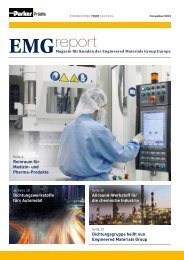
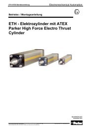
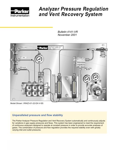
Model Shown: VRAZ3-01-22-DX-V-SS<br />
Unparalleled pressure <strong>and</strong> flow stability<br />
The <strong>Parker</strong> <strong>Analyzer</strong> <strong>Pressure</strong> <strong>Regulation</strong> <strong>and</strong> <strong>Vent</strong> <strong>Recovery</strong> <strong>System</strong> automatically <strong>and</strong> continuously adjusts<br />
for variations in gas supply pressures <strong>and</strong> flows. This system has been engineered to meet the requirement<br />
of continuous analyzers designed to operate at constant pressure in order to provide accurate analyses of<br />
gases. The combination of pressure <strong>and</strong> flow regulation provides the required stability even with greatly<br />
varying inlet <strong>and</strong> outlet pressures.
<strong>Analyzer</strong> <strong>Pressure</strong> <strong>Regulation</strong> <strong>and</strong> <strong>Vent</strong> <strong>Recovery</strong> <strong>System</strong><br />
Features<br />
• Designed for a zero, a calibration, <strong>and</strong> up to two<br />
sample streams<br />
• Capabilities<br />
Stream switching<br />
Sample filtering<br />
Flow <strong>and</strong> pressure regulation<br />
• Regulator controls analyzer pressure<br />
• Metering valves control<br />
<strong>Analyzer</strong> flow<br />
Stream by-pass flow<br />
• Flowmeters indicate stability of<br />
<strong>Analyzer</strong> flow<br />
Stream by-pass flow<br />
• <strong>Pressure</strong> gauges indicate<br />
Sample inlet pressure<br />
<strong>Pressure</strong> to the analyzer<br />
<strong>Pressure</strong> from the filter<br />
• Utilizes <strong>Parker</strong><br />
R-Max Stream Switching <strong>System</strong><br />
MB Series Ball Valves<br />
HR Series Metering Valves<br />
IR5000 <strong>Pressure</strong> Regulator<br />
SC Flow Controller<br />
Balston ® Particulate Filtration<br />
CPI Connectors<br />
• 100% Factory Tested<br />
• Patent Pending<br />
• Custom Engineered <strong>System</strong>s Available<br />
Operating Conditions<br />
• <strong>Pressure</strong> Rating:<br />
200 psig (14 bar) maximum<br />
• Temperature Rating:<br />
Media -40 °F to 200 °F (-40 °C to 93 °C)<br />
Ambient -40 °F to 140 °F (-40 °C to 60 °C)<br />
Functional Performance<br />
• <strong>Pressure</strong> Ratings:<br />
IR5000 <strong>Pressure</strong> Regulator<br />
3500 psig (241 bar)<br />
MB Series Ball Valve<br />
3000 psig (207 bar)<br />
R-Max Stream Switching <strong>System</strong><br />
500 psig (34 bar)<br />
HR Series Metering Valve<br />
250 psig (17 bar)<br />
Flowmeter<br />
200 psig (14 bar)<br />
SC Flow Controller<br />
150 psig (10 bar)<br />
Materials of Construction*<br />
Wetted<br />
R-Max <strong>System</strong><br />
Base, Body <strong>and</strong> Stems ............. 316 Stainless Steel<br />
Upper <strong>and</strong> Lower Seats ............................... PCTFE<br />
Seals ...................................... Fluorocarbon Rubber<br />
IR5000 Regulator<br />
Body ........................................ 316L Stainless Steel<br />
Diaphragm ...................................... Hastelloy C-22 ®<br />
Compression Member ................................ Inconel ®<br />
Poppet ......................................................... Elgiloy ®<br />
Poppet Spring ............................................. Inconel ®<br />
Carrier .............................................. Stainless Steel<br />
Seat ............................................................. PCTFE<br />
Back-up O-ring ...................... Fluorocarbon Rubber<br />
Inlet Screen/Filter ................... 316L Stainless Steel<br />
MB Ball Valves<br />
Body <strong>and</strong> Stem ......................... 316 Stainless Steel<br />
Seat/Packing......................... Perfluoroalkoxy (PFA)<br />
HR Metering Valves<br />
Cartridge Components ............. 316 Stainless Steel<br />
Orifice Liner ................................. Mica Filled PTFE<br />
Stem Seals ............................ Fluorocarbon Rubber<br />
SC Controller<br />
Body <strong>and</strong> Piston ..................... 316L Stainless Steel<br />
Seat <strong>and</strong> Seals ...................... Fluorocarbon Rubber<br />
Diaphragm ...................................... Hastelloy C-22 ®<br />
Flowmeters<br />
Body .......................................... 316 Stainless Steel<br />
Tube ............................................ Borosilicate Glass<br />
Float ................................................................ Glass<br />
Float Stops...................................................... PTFE<br />
Gauges<br />
Body .......................................... 316 Stainless Steel<br />
Bourdon Tube ........................... 316 Stainless Steel<br />
Fittings ......................................... 316 Stainless Steel<br />
Tubing .......................................... 316 Stainless Steel<br />
Non-wetted<br />
Panel ............................................ 304 Stainless Steel<br />
Brackets ....................................... 304 Stainless Steel<br />
Hardware ............................................ Stainless Steel<br />
Operating H<strong>and</strong>les .................. ABS Plastic, Nylon 6/6<br />
Gauge <strong>and</strong> Flowmeter Shields ............ Polycarbonate<br />
* Materials of construction for stainless steel systems.<br />
Consult factory for optional materials of construction.<br />
Hastelloy C-22 is a registered trademark of Haynes International, Inc.<br />
Inconel is a registered trademark of Inco Alloys International<br />
Elgiloy is a registered trademark of Elgiloy Company<br />
© Copyright 2001, <strong>Parker</strong> Hannifin Corporation. All Rights Reserved.<br />
2<br />
<strong>Parker</strong> Hannifin Corporation<br />
Instrumentation Valve Division<br />
Jacksonville, Alabama
<strong>Analyzer</strong> <strong>Pressure</strong> <strong>Regulation</strong> <strong>and</strong> <strong>Vent</strong> <strong>Recovery</strong> <strong>System</strong><br />
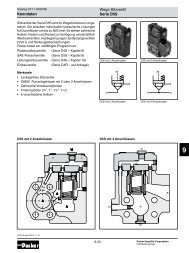
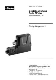
Typical Two Stream <strong>Vent</strong> <strong>Recovery</strong> <strong>System</strong><br />
Performance Example 1 - Varying<br />
Inlet <strong>Pressure</strong> with Constant<br />
Outlet <strong>Pressure</strong><br />
Performance Example 2 - Varying<br />
Outlet <strong>Pressure</strong> with Constant<br />
Inlet <strong>Pressure</strong><br />
<strong>Analyzer</strong> <strong>Pressure</strong> set to 5 psig (0.3 bar);<br />
Supply <strong>Pressure</strong> varied from 20 to 90 psig (1.4 to 6.2 bar)<br />
Options<br />
<strong>Analyzer</strong> <strong>Pressure</strong> set to 12.7 psia (0.87 bar);<br />
Supply <strong>Pressure</strong> set to 14.5 psia (1.01 bar);<br />
Outlet <strong>Pressure</strong> varied from 1 to 11 psia (0.07 to 0.76 bar)<br />
By-pass Filter - Approximately 90% of the inlet flow by-passes the cartridge filter <strong>and</strong> exists the filter bowl. This<br />
provides three benefits: 1) It reduces the transport time of the sample stream from the process line to the analyzer;<br />
2) Provides a continuous flushing action on the filter element; <strong>and</strong>, 3) The life of the filter element is greatly<br />
extended since only a small percentage of the flow is filtered - <strong>and</strong> only when the stream is selected for analysis.<br />
Manual Stream Switching - The R-Max Stream Switching <strong>System</strong> is replaced with two-way <strong>and</strong> three-way<br />
MB Series manual Ball Valves. The optional By-pass Filter(s), if ordered, is mounted as a st<strong>and</strong>-alone unit<br />
downstream of the sample inlet MB Series manual Ball Valve(s).<br />
Integral Aspirator - A <strong>Parker</strong> VC Vacuum Generator is added between the Flow Controller <strong>and</strong> MB Series Ball<br />
Valve on the Sample Return line. A <strong>Parker</strong> IR4000 <strong>Pressure</strong> Regulator is also added to control the vacuum<br />
generated.<br />
Filter Purge Valve - A three-way MB Series manual Ball Valve is placed upstream of the Filter to enable switching<br />
between sample <strong>and</strong> purge gas.<br />
Aspirator <strong>and</strong> Filter Purge Valve - Adds both the Integral Aspirator <strong>and</strong> the Filter Purge components to the<br />
panel.<br />
3<br />
<strong>Parker</strong> Hannifin Corporation<br />
Instrumentation Valve Division<br />
Jacksonville, Alabama
<strong>Analyzer</strong> <strong>Pressure</strong> <strong>Regulation</strong> <strong>and</strong> <strong>Vent</strong> <strong>Recovery</strong> <strong>System</strong><br />
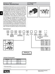
How to Order<br />
VRA Z 3 - 3 4 - 4 2 - S1 - V - SS<br />
<strong>System</strong> Series<br />
VRA = Automatic Stream Switch<br />
VRM = Manual Stream Switch<br />
<strong>System</strong> Options<br />
A = Integral Aspirator<br />
B = Filter Purge Valve<br />
C = Aspirator & Filter Purge Valve<br />
Z = None of the above<br />
Number of Streams<br />
3 = Three<br />
4 = Four<br />
Inlet <strong>Pressure</strong> Gauge<br />
0 = 30 psig<br />
1 = 60 psig<br />
2 = 100 psig<br />
3 = 200 psig<br />
<strong>Pressure</strong> Regulator<br />
0 = 0 - 5 psig<br />
1 = 1 - 30 psig<br />
2 = 1 - 60 psig<br />
3 = 2 - 100 psig<br />
4 = 2 - 250 psig<br />
* <strong>System</strong>s without a By-pass Filter will have a Tee branching from<br />
the Sample Stream Switch inlet to the By-pass Flowmeter.<br />
Component Materials<br />
SS = Stainless Steel<br />
Seal Material<br />
V = Fluorocarbon Rubber<br />
By-pass Filter<br />
0 - No Filter*<br />
S5 - 5 Micron Sintered Metal<br />
S1 - 10 Micron Sintered Metal<br />
S2 - 20 Micron Sintered Metal<br />
S4 - 40 Micron Sintered Metal<br />
S7 - 70 Micron Sintered Metal<br />
S0 - 100 Micron Sintered Metal<br />
DQ - 93% Microfibre @ 0.01 Micron<br />
DX - 99.999% Microfibre @ 0.01 Micron<br />
<strong>Analyzer</strong> Flowmeter Range (LPM)<br />
0 = 0 - 2.2<br />
2 = 0 - 4.5<br />
4 = 0 - 6.1<br />
6 = 0 - 10.7<br />
By-pass Flowmeter Range (LPM)<br />
0 = 0 - 2.2<br />
2 = 0 - 4.5<br />
4 = 0 - 6.1<br />
6 = 0 - 10.7<br />
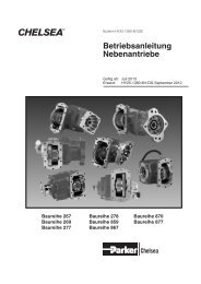
Dimensions**<br />
** For a three or four stream VRAZ <strong>System</strong> Series. Subject to change without notice.<br />
( ) Denotes dimensions in millimeters<br />
Bulletin 4141-VR, 5M, 11/01<br />
<strong>Parker</strong> Hannifin Corporation<br />
Instrumentation Valve Division<br />
2651 Alabama Highway 21 North<br />
Jacksonville, AL 36265-9681<br />
Phone: (256) 435-2130<br />
Fax: (256) 435-7718<br />
www.parker.com/IVD