Gasoline and Diesel Fuel Injection: Operation ... - Pearson Canada
Gasoline and Diesel Fuel Injection: Operation ... - Pearson Canada
Gasoline and Diesel Fuel Injection: Operation ... - Pearson Canada

You also want an ePaper? Increase the reach of your titles
YUMPU automatically turns print PDFs into web optimized ePapers that Google loves.
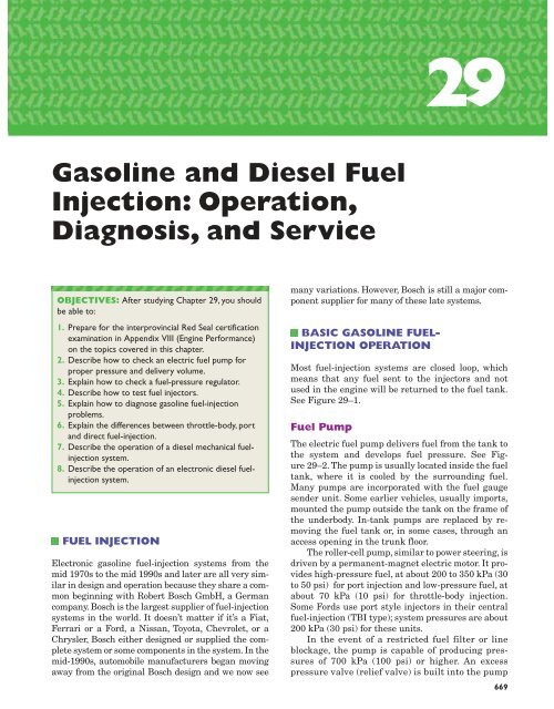
29<br />
<strong>Gasoline</strong> <strong>and</strong> <strong>Diesel</strong> <strong>Fuel</strong><br />
<strong>Injection</strong>: <strong>Operation</strong>,<br />
Diagnosis, <strong>and</strong> Service<br />
OBJECTIVES: After studying Chapter 29, you should<br />
be able to:<br />
1. Prepare for the interprovincial Red Seal certification<br />
examination in Appendix VIII (Engine Performance)<br />
on the topics covered in this chapter.<br />
2. Describe how to check an electric fuel pump for<br />
proper pressure <strong>and</strong> delivery volume.<br />
3. Explain how to check a fuel-pressure regulator.<br />
4. Describe how to test fuel injectors.<br />
5. Explain how to diagnose gasoline fuel-injection<br />
problems.<br />
6. Explain the differences between throttle-body, port<br />
<strong>and</strong> direct fuel-injection.<br />
7. Describe the operation of a diesel mechanical fuelinjection<br />
system.<br />
8. Describe the operation of an electronic diesel fuelinjection<br />
system.<br />
FUEL INJECTION<br />
Electronic gasoline fuel-injection systems from the<br />
mid 1970s to the mid 1990s <strong>and</strong> later are all very similar<br />
in design <strong>and</strong> operation because they share a common<br />
beginning with Robert Bosch GmbH, a German<br />
company. Bosch is the largest supplier of fuel-injection<br />
systems in the world. It doesn’t matter if it’s a Fiat,<br />
Ferrari or a Ford, a Nissan, Toyota, Chevrolet, or a<br />
Chrysler, Bosch either designed or supplied the complete<br />
system or some components in the system. In the<br />
mid-1990s, automobile manufacturers began moving<br />
away from the original Bosch design <strong>and</strong> we now see<br />
many variations. However, Bosch is still a major component<br />
supplier for many of these late systems.<br />
BASIC GASOLINE FUEL-<br />
INJECTION OPERATION<br />
Most fuel-injection systems are closed loop, which<br />
means that any fuel sent to the injectors <strong>and</strong> not<br />
used in the engine will be returned to the fuel tank.<br />
See Figure 29–1.<br />
<strong>Fuel</strong> Pump<br />
The electric fuel pump delivers fuel from the tank to<br />
the system <strong>and</strong> develops fuel pressure. See Figure<br />
29–2. The pump is usually located inside the fuel<br />
tank, where it is cooled by the surrounding fuel.<br />
Many pumps are incorporated with the fuel gauge<br />
sender unit. Some earlier vehicles, usually imports,<br />
mounted the pump outside the tank on the frame of<br />
the underbody. In-tank pumps are replaced by removing<br />
the fuel tank or, in some cases, through an<br />
access opening in the trunk floor.<br />
The roller-cell pump, similar to power steering, is<br />
driven by a permanent-magnet electric motor. It provides<br />
high-pressure fuel, at about 200 to 350 kPa (30<br />
to 50 psi) for port injection <strong>and</strong> low-pressure fuel, at<br />
about 70 kPa (10 psi) for throttle-body injection.<br />
Some Fords use port style injectors in their central<br />
fuel-injection (TBI type); system pressures are about<br />
200 kPa (30 psi) for these units.<br />
In the event of a restricted fuel filter or line<br />
blockage, the pump is capable of producing pressures<br />
of 700 kPa (100 psi) or higher. An excess<br />
pressure valve (relief valve) is built into the pump<br />
669
670 CHAPTER 29<br />
Figure 29–1 Typical port fuel-injection system, indicating the location of various<br />
components. Notice that the fuel pressure regulator is located on the fuel return side of<br />
the system. The computer does not control fuel pressure, but does control the<br />
operation of the electric fuel pump (on most systems) <strong>and</strong> the pulsing on <strong>and</strong> off of the<br />
injectors.<br />
Figure 29–2 Schematic of a roller-cell fuel pump. Note #5 non-return valve, which prevents fuel pressure from bleeding<br />
back through the pump, <strong>and</strong> #2 pressure limiter (relief) valve, which acts as a safety valve if the fuel filter or line is restricted.<br />
(Courtesy Robert Bosch)
<strong>Gasoline</strong> <strong>and</strong> <strong>Diesel</strong> <strong>Fuel</strong> <strong>Injection</strong>: <strong>Operation</strong>, Diagnosis, <strong>and</strong> Service 671<br />
Figure 29–3 The fuel filter is located between the fuel<br />
pump <strong>and</strong> the fuel rail. Many filters are directional <strong>and</strong> have<br />
an arrow (or different sized fittings) to prevent incorrect<br />
installation. Most systems also have a filter “sock” at the<br />
fuel tank pick-up. (Courtesy Robert Bosch)<br />
as a safety feature. A one-way check valve is also<br />
built into the pump outlet to prevent any fuel pressure<br />
in the lines or rail from bleeding back through<br />
the pump.<br />
<strong>Fuel</strong> Filter<br />
The fuel filter is a very important service item. See<br />
Figure 29–3. It prevents any rust or dirt in the fuel<br />
from reaching the fuel injectors where damage<br />
would occur; injector blockage, sticking or leakage<br />
are the usual result.<br />
The filter is directional <strong>and</strong> may have an arrow<br />
or different sized fittings to prevent mounting backwards.<br />
Filters are normally replaced after a given<br />
number of kilometres or whenever major service is<br />
performed, e.g., fuel pump replacement or injector<br />
cleaning. <strong>Fuel</strong> system pressures must be released<br />
<strong>and</strong> the fuel tank cap removed before loosening filter<br />
lines. Pressurized fuel can spray for a long distance,<br />
causing personal injury or a fire.<br />
<strong>Fuel</strong> Rail (Port <strong>Injection</strong>)<br />
The fuel rail (or ring) acts as a manifold supplying<br />
fuel to each injector. See Figure 29–4. It also acts<br />
as a mounting point for the fuel-pressure regulator.<br />
Some domestic vehicles have the regulator riveted<br />
to the fuel rail; both are supplied if either<br />
needs replacing. The fuel injectors are sealed with<br />
O rings where they mount to the rail; the O rings<br />
should be replaced whenever the rail is removed<br />
from the injectors.<br />
Domestic fuel rails usually have a fuel-pressure<br />
test fitting (Schrader valve) mounted on the rail,<br />
which makes servicing much easier. Many imported<br />
vehicles do not use Schrader valves <strong>and</strong> require special<br />
adaptors to test system pressures <strong>and</strong> fuel volume.<br />
Figure 29–4 The fuel rail is a hollow manifold that<br />
supplies fuel to the injectors. Excess fuel not used in the<br />
engine flows through a pressure regulator (usually<br />
mounted on the rail) <strong>and</strong> returns to the tank. (Courtesy<br />
DaimlerChrysler Corporation)<br />
<strong>Fuel</strong> Injectors<br />
Electronic fuel injectors are liquid-control solenoids<br />
that open when electrically activated. See Figure<br />
29–5. The injectors are pulsed on <strong>and</strong> off to control<br />
fuel volume. The longer the injectors are held open,<br />
the greater the amount of fuel injected into the manifold<br />
or intake port. Injectors are never operated at a<br />
100% duty cycle. “On” time is called “pulse width”;<br />
the longer the pulse width, the greater the fuel flow;<br />
“on” time is usually in the 5 to 15 millisecond range.<br />
Port <strong>Injection</strong><br />
Port injection systems used on gasoline-powered engines<br />
inject a fine mist of fuel into the intake manifold<br />
just above the intake valve. The pressure in the<br />
intake manifold is below atmospheric pressure on a<br />
running engine, <strong>and</strong> the manifold is therefore a vacuum.<br />
See Figure 29–6.<br />
One major advantage of using port injection instead<br />
of the simpler throttle-body injection is that intake<br />
manifolds on port-injected engines only contain<br />
air, not a mixture of air <strong>and</strong> fuel. No pre-heating of<br />
the manifold is required to vaporize the fuel. This allows<br />
a cooler charge of intake air, which increases<br />
power. Another advantage is the equal volume of<br />
fuel provided to each cylinder. These “dry” manifolds<br />
also allow the engine design engineer the opportunity<br />
to design long, tuned intake-manifold runners<br />
that help the engine produce increased torque at<br />
lower engine speeds.
672 CHAPTER 29<br />
Figure 29–5 Cross-section of a typical port fuel-injection nozzle assembly. These injectors are serviced as an assembly<br />
only; no part replacement or service is possible other than cleaning or external O-ring replacement. Contamination at the<br />
needle valve area is a common problem, especially with older type injectors. Later injectors, called deposit-resistant, changed<br />
the tip design to reduce the formation of injector deposits.<br />
Figure 29–6 A typical port-injection system squirts fuel<br />
into the low pressure (vacuum) of the intake manifold,<br />
about 75 mm (3 in.) from the intake valve. A buildup of<br />
soft carbon on the intake valve often resulted from this<br />
design. The petroleum industry responded in the mid-<br />
1990s by increasing the percentage of detergent in<br />
gasoline. The detergent also reduced injector<br />
contamination.<br />
NOTE: Some port-injection systems used on engines<br />
with four or more valves per cylinder may use two injectors<br />
per cylinder. One injector is used all the time,<br />
<strong>and</strong> the second injector is operated by the computer<br />
when high engine speed <strong>and</strong> high-load conditions are<br />
detected by the computer. Typically, the second injector<br />
injects fuel into the high-speed intake ports of the manifold.<br />
This system permits good low-speed power <strong>and</strong><br />
throttle response as well as superior high-speed power.<br />
<strong>Fuel</strong> Pressure Regulator:<br />
Port <strong>Injection</strong><br />
<strong>Fuel</strong> injectors that inject fuel into the intake port<br />
are influenced by intake manifold vacuum. At idle,<br />
manifold vacuum is very strong <strong>and</strong> a given<br />
amount of fuel flows. As the throttle opens, manifold<br />
vacuum diminishes (pressure in the manifold<br />
rises) <strong>and</strong> less fuel will flow because of the higher<br />
pressure at the injector tip. Vacuum-modulated<br />
pressure regulators increase fuel pressure about<br />
35 kPa (5 psi) as the throttle is opened. See Figure<br />
29–7. This compensates for the increase in manifold<br />
pressure.<br />
Any excess fuel not injected into the engine returns<br />
to the tank via a return line.<br />
The pressure regulator also prevents fuel pressure<br />
from bleeding into the return line when the engine<br />
is shut off; this maintains pressurized fuel at<br />
the rail <strong>and</strong> injectors for faster starting.
<strong>Gasoline</strong> <strong>and</strong> <strong>Diesel</strong> <strong>Fuel</strong> <strong>Injection</strong>: <strong>Operation</strong>, Diagnosis, <strong>and</strong> Service 673<br />
Figure 29–7 The vacuum-modulated pressure regulator<br />
controls system fuel pressure with a spring-loaded<br />
diaphragm. (a) Strong manifold vacuum (closed throttle)<br />
works against the spring <strong>and</strong> fuel pressure decreases. (b) As<br />
manifold vacuum drops (throttle opens), full spring pressure<br />
is now exerted on the diaphragm <strong>and</strong> fuel pressure rises.<br />
(Courtesy DaimlerChrysler Corporation)<br />
Injector Firing Strategy<br />
<strong>Fuel</strong> injectors have a number of operating strategies.<br />
They can all be fired at the same time (see Figure<br />
29–8) with only one driver transistor. This is<br />
known as simultaneous injection; it is not timed.<br />
Some systems operate with two driver transistors;<br />
half of the injectors fire on one revolution, the other<br />
half fire on the second revolution; they also are not<br />
timed. Sequential injection, which requires a separate<br />
ground wire <strong>and</strong> transistor for each injector<br />
(ground side controlled), is timed. <strong>Injection</strong> usually<br />
occurs at the end of the exhaust stroke as the intake<br />
valve is opening.<br />
Sequential injection has a number of advantages<br />
over simultaneous injection: 1) Emissions<br />
are reduced during low RPM <strong>and</strong> idle conditions.<br />
2) It works with waste spark ignitions that fire the<br />
spark plug every revolution. 3) OBD II systems<br />
have the ability to cancel fuel delivery to any cylinder<br />
that is misfiring. This protects the catalytic<br />
converter.<br />
Many imported vehicles use a resistor, which reduces<br />
the voltage at the injectors to approximately<br />
one-quarter of source voltage. This allows the use of<br />
low resistance injectors, which improves injector response.<br />
Domestic vehicles operate the injectors at<br />
source voltage <strong>and</strong> regulate injector response with<br />
the PCM.<br />
Overspeed protection is also built into most computer<br />
programs. If the engine is operated above red<br />
line or is over-revved in neutral, the computer cuts<br />
off every second injector (or similar strategy) to bring<br />
the RPM down to a safe level.<br />
<strong>Fuel</strong> Pump Electrical Circuits<br />
The computer usually controls the operation of the<br />
electric fuel pump, located in (or near) the fuel tank.<br />
When the ignition switch is first turned on, the computer<br />
energizes the fuel pump relay <strong>and</strong> the pump<br />
operates. See Figure 29–9. If the computer does not<br />
receive a signal that the engine is rotating, the pump<br />
will be shut off after 2 to 3 seconds. When the computer<br />
receives information that the engine is being<br />
cranked, or has started, it continues to energize the<br />
fuel pump. The signal may come from one or more of<br />
the following:<br />
■ Movement inside the vane airflow sensor from<br />
air entering the engine.<br />
■ Oil pressure is noted at the oil pressure sender.<br />
■ An ignition tach signal (RPM) is present; this is<br />
the most common.<br />
Figure 29–8 Wiring schematic<br />
for a simultaneous injection<br />
system. (Courtesy Toyota<br />
<strong>Canada</strong> Inc.)
674 CHAPTER 29<br />
Figure 29–9 Schematic of a Ford<br />
fuel pump electrical circuit. After<br />
2 to 3 seconds of pump operation,<br />
the computer (ECA) must receive<br />
an ignition signal (indicating the<br />
engine is rotating) or it will shut<br />
down the fuel pump relay. Note<br />
the inertia safety switch in the<br />
pump circuit. (Courtesy Ford<br />
Motor Co.)<br />
Figure 29–10 The inertia switch is used to shut off the electric fuel pump in case of an accident. Do not reset the switch<br />
before checking for fuel leaks at the tank, lines, or engine compartment. (Courtesy Ford Motor Co.)<br />
NOTE: This is a safety feature: if the engine stalls <strong>and</strong><br />
the tachometer (engine speed) signal is lost, the computer<br />
will shut off (de-energize) the fuel pump relay<br />
<strong>and</strong> stop the fuel pump.<br />
Inertia Safety Switch<br />
Ford, Jaguar <strong>and</strong> Fiat use an inertia switch in the<br />
fuel pump circuit to shut off the fuel pump in case of<br />
an accident. See Figure 29–10. A permanent magnet<br />
holds a steel ball in place; if an accident, or sharp impact,<br />
occurs, the steel ball breaks free <strong>and</strong> strikes a<br />
target plate, which opens the switch contacts, shut-<br />
ting off power to the pump. The switch is reset manually<br />
by depressing the reset button. Switch locations<br />
vary between vehicles; the switch may be in the<br />
trunk, on the firewall or behind a kick panel. Check<br />
the manual for location.<br />
THROTTLE BODY INJECTION<br />
Throttle-body injection (TBI) is also known as Central<br />
<strong>Fuel</strong> <strong>Injection</strong> (CFI) or Single-Point <strong>Injection</strong>.<br />
Throttle-body type of fuel injection uses one or two injectors<br />
(nozzles) to spray atomized fuel into the throttle<br />
body, which is similar to the base of a carburetor.
<strong>Gasoline</strong> <strong>and</strong> <strong>Diesel</strong> <strong>Fuel</strong> <strong>Injection</strong>: <strong>Operation</strong>, Diagnosis, <strong>and</strong> Service 675<br />
Figure 29–11 <strong>Fuel</strong> is injected<br />
above the throttle plate in this<br />
CFI system. The pressure<br />
regulator is not vacuummodulated,<br />
as intake manifold<br />
vacuum does not have a major<br />
influence on injection rates.<br />
(Courtesy Ford Motor Co.)<br />
Figure 29–12 <strong>Fuel</strong> delivery <strong>and</strong> return lines on this TBI system are similar to port fuel injection. (Courtesy General<br />
Motors)<br />
Air <strong>and</strong> fuel mix in the throttle-body unit <strong>and</strong> flow as<br />
a mixture down the intake manifold to the intake<br />
valves. See Figure 29–11. The fuel pump, filter, <strong>and</strong><br />
lines are essentially the same as port injection. See<br />
Figure 29–12. Because fuel is injected above the<br />
throttle plate, intake manifold vacuum has no major<br />
influence on the injector. <strong>Fuel</strong> pressure regulators are<br />
not vacuum-modulated; fuel pressure is constant at<br />
70 to 105 kPa (10 to 15 psi) depending on the model.<br />
The ball-type tip of the TBI/CFI fuel injector is<br />
much larger than the needle tips of port injectors<br />
<strong>and</strong> it is prone to drip after the engine is shut off. See<br />
Figure 29–13. Some TBI pressure regulators (GM,<br />
Renault) have a bleed groove built into the pressureregulator<br />
valve seat to relieve fuel pressure after the<br />
engine is turned off. Be aware of this condition when<br />
testing residual fuel pressure; there will be no pressure<br />
remaining after a few seconds.<br />
A typical TBI system uses a throttle-position (TP)<br />
sensor <strong>and</strong> an idle air-control (IAC) valve. The TP is<br />
an input to the computer <strong>and</strong> the IAC is an output<br />
from the computer. The throttle-body injection unit<br />
costs less to manufacture, because it only uses one or<br />
two injectors (nozzles), whereas port-injection systems<br />
require an injector for every cylinder plus the additional<br />
computer capabilities to control all the injectors.<br />
Throttle body injection provides better driveability<br />
<strong>and</strong> fuel economy than a mechanical (or electronically<br />
controlled) carburetor, however all of the distribution<br />
<strong>and</strong> vaporization problems associated with<br />
carburetted systems apply, as both air <strong>and</strong> fuel flow<br />
through the manifold. Unlike a port-injection system,<br />
many TBI units require that heated air be used<br />
with a heated intake manifold system to help vaporize<br />
the fuel that is injected into the incoming air inside<br />
the throttle-body unit.
676 CHAPTER 29<br />
Figure 29–13 A low-pressure TBI/CFI fuel injector feeds all cylinders<br />
compared to a port fuel injector, which feeds only one cylinder. The<br />
larger ball-type injector tip is prone to leak or drip when the engine has<br />
been shut off. (Courtesy Ford Motor Co.)<br />
BOSCH CONTINUOUS<br />
INJECTION (CIS)<br />
Bosch continuous injection systems are also known as<br />
K-Jetronic injection: K st<strong>and</strong>s for konstant in German.<br />
They are found on many 1970s to 1990s European<br />
vehicles (i.e., Audi, BMW, Mercedes, Volkswagen<br />
<strong>and</strong> Volvo, never on Asian or domestic automobiles).<br />
Early CIS systems were mechanically operated;<br />
there is no computer. See Figure 29–14. Later systems,<br />
known as CIS-E, used a computer, a lambda (oxygen)<br />
sensor <strong>and</strong> a frequency valve to trim fuel mixtures.<br />
The frequency valve changes internal fuel pressures<br />
inside the fuel distributor to vary the mixture.<br />
Figure 29–14 Schematic of a Bosch CIS mechanical injection system. These units are found only on European vehicles.<br />
(Courtesy Robert Bosch)
<strong>Gasoline</strong> <strong>and</strong> <strong>Diesel</strong> <strong>Fuel</strong> <strong>Injection</strong>: <strong>Operation</strong>, Diagnosis, <strong>and</strong> Service 677<br />
System <strong>Operation</strong><br />
Filtered fuel is pumped to the lower chamber of the<br />
mixture control unit where it is regulated to about<br />
500 kPa (75 psi) by the pressure regulator. Excess<br />
fuel is returned to the tank.<br />
Basic fuel control begins with an airflow sensor<br />
plate mounted next to the mixture control unit. Air<br />
entering the engine lifts the sensor plate; the<br />
greater the flow of air, the higher the plate is lifted.<br />
The arm on the airflow sensor plate contacts a fuel<br />
control valve called a control plunger. As the sensor<br />
plate lifts, it pushes on the control plunger, which<br />
also lifts, increasing fuel delivery. See Figure 29–15.<br />
<strong>Fuel</strong> flows from the mixture control unit to springloaded<br />
mechanical fuel injectors that open automatically<br />
when fuel pressure reaches 330 kPa (50 psi).<br />
CENTRAL PORT INJECTION<br />
The General Motors CPI system is a combination of<br />
a single electronic TBI-type injector <strong>and</strong> mechanical<br />
spring-loaded fuel injectors. See the manifold design<br />
in Chapter 9, Figure 9–42A.<br />
The CPI fuel system is located inside a two-piece<br />
split intake manifold. <strong>Fuel</strong> arriving at the CPI unit<br />
is regulated by a built-in pressure regulator that<br />
returns unused fuel to the tank. The single maxiinjector<br />
(computer activated) injects fuel into a base,<br />
which contains six nylon tubes connected to six nylon<br />
fuel injectors (poppet nozzles). <strong>Fuel</strong> pressure at<br />
the injectors overcomes spring tension <strong>and</strong> fuel is injected<br />
into the ports. See Figure 29–16.<br />
Figure 29–15 <strong>Fuel</strong> delivery in a<br />
Bosch CIS fuel distributor is metered<br />
by a control plunger, which is lifted<br />
by airflow at the sensor plate.<br />
(Courtesy Robert Bosch)<br />
Figure 29–16 Central port injection (CPI) operation. (Courtesy General Motors)
678 CHAPTER 29<br />
Later designs use separate injector solenoids<br />
for each poppet valve, rather than a single maxiinjector.<br />
These systems are used primarily with V-<br />
6 <strong>and</strong> V-8 light truck engines.<br />
RETURNLESS FUEL INJECTION<br />
The most common injection system found from the<br />
mid 1990s to date is returnless fuel injection. An<br />
in-tank fuel pump module contains the pump, filter,<br />
pressure regulator, <strong>and</strong> fuel gauge, all in one<br />
unit. See Figure 29–17. There is nothing outside<br />
the tank, other than a single fuel line, rail, <strong>and</strong> injectors.<br />
See Figure 29–18. The extra computing<br />
memory of the OBD II processor allows fuel volume<br />
to be tailored to dem<strong>and</strong>, regardless of changes in<br />
manifold vacuum.<br />
Removing the rear seat (or trunk mat) <strong>and</strong> servicehole<br />
cover allows access to the unit without removing<br />
the tank in most instances.<br />
DaimlerChrysler was one of the first (mid-1990s)<br />
to use returnless injection with their V-8 <strong>and</strong> V-10<br />
engines. Since then it has been adopted by many domestic<br />
<strong>and</strong> import manufacturers <strong>and</strong> has become<br />
the st<strong>and</strong>ard around the world.<br />
Figure 29–17 The fuel pump, gauge, <strong>and</strong> pressure regulator are all mounted<br />
inside the tank with returnless fuel injection. (Courtesy Toyota <strong>Canada</strong> Inc.)
<strong>Gasoline</strong> <strong>and</strong> <strong>Diesel</strong> <strong>Fuel</strong> <strong>Injection</strong>: <strong>Operation</strong>, Diagnosis, <strong>and</strong> Service 679<br />
Figure 29–18 <strong>Fuel</strong> rails with returnless fuel<br />
injection contain an inlet fitting <strong>and</strong><br />
pressure-gauge port. There is no return<br />
line. Pressure remains constant at 275 kPa<br />
(40 psi). (Courtesy DaimlerChrysler<br />
Corporation)<br />
DIRECT FUEL INJECTION<br />
A few Asian manufacturers—Mitsubishi, Toyota,<br />
<strong>and</strong> Isuzu—are using gasoline direct injection (GDI)<br />
with selected models. GDI sprays high-pressure fuel<br />
(8000 to 13 000 kPa, 1200 to 1950 psi) into the combustion<br />
chamber as the piston approaches the top of<br />
the compression stroke. See Figure 29–19.<br />
The combination of high-pressure swirl injectors,<br />
with almost instant vaporization, <strong>and</strong> modified<br />
combustion chamber <strong>and</strong> port design allows the engine<br />
to run with a much leaner air/fuel mixture than<br />
conventional intake port injection. <strong>Fuel</strong> economy has<br />
shown a major improvement <strong>and</strong> engine emissions<br />
have been reduced.<br />
Lean-burn engines traditionally lower hydrocarbon<br />
(HC) <strong>and</strong> carbon monoxide (CO) emissions; however,<br />
oxides of nitrogen (NO x ) emissions rise because<br />
of the elevated combustion temperatures created by<br />
lean mixtures. Increasing the amount of exhaust gas<br />
(EGR) fed into the incoming air <strong>and</strong> a special catalytic<br />
converter reduces NO x to a very low level. It is<br />
expected that GDI engines will become more common<br />
as emission <strong>and</strong> fuel economy st<strong>and</strong>ards become<br />
more stringent.<br />
Diagnosing Electronic<br />
<strong>Fuel</strong>-<strong>Injection</strong> Problems<br />
Using Visual Inspection<br />
All fuel-injection systems require the proper amount<br />
of clean fuel delivered to the system at the proper<br />
pressure <strong>and</strong> the correct amount of filtered air. The<br />
following items should be carefully inspected before<br />
proceeding to more detailed tests.<br />
■ Check the air filter <strong>and</strong> replace as needed.<br />
■ Check the air induction system for obstructions.<br />
T E C H T I P<br />
✔<br />
No Spark, No Squirt<br />
Most electronic fuel-injection computer systems use the<br />
ignition primary (pickup coil or crank sensor) pulse as the<br />
trigger for when to inject (squirt) fuel from the injectors<br />
(nozzles). If this signal were not present, no fuel would be<br />
injected. Because this pulse is also necessary to trigger<br />
the module to create a spark from the coil, it can be said<br />
that “no spark” could also mean “no squirt.” Therefore, if<br />
the cause of a no-start condition is observed to be a lack<br />
of fuel injection, do not start testing or replacing fuelsystem<br />
components until the ignition system is checked<br />
for proper operation.<br />
■ Check the condition of all vacuum hoses. Replace<br />
any hose that is split, soft (mushy), or brittle. Be<br />
sure to use the correct type of hose designed for<br />
use on a vacuum system. Using fuel line hose<br />
instead of vacuum hose can cause the hose to be<br />
sucked closed, creating more problems. This is<br />
especially true for the PCV valve hose.<br />
■ Check the positive crankcase ventilation (PCV)<br />
valve for proper operation or replacement as<br />
needed.<br />
NOTE: The use of an incorrect PCV valve can cause a<br />
rough idle or stalling.<br />
■ Check all fuel-injection electrical connections for<br />
corrosion or damage.<br />
■ Check for gasoline at the vacuum port of the fuel<br />
pressure regulator if the vehicle is so equipped.<br />
<strong>Gasoline</strong> in the vacuum hose at the fuel pressure
680 CHAPTER 29<br />
Figure 29–19 <strong>Gasoline</strong> direct injection (GDI). Note the high-pressure swirl fuel injector at the combustion chamber.<br />
(Courtesy Toyota <strong>Canada</strong> Inc.)<br />
T E C H T I P<br />
✔<br />
The Ear Test<br />
No,this is not a test of your hearing,but rather using your<br />
ear to check that the electric fuel pump is operating. The<br />
electric fuel pump inside the fuel tank is often difficult to<br />
hear running, especially in a noisy shop environment. A<br />
commonly used trick to better hear the pump is to use a<br />
funnel in the fuel filter neck.<br />
regulator indicates that the regulator is defective<br />
<strong>and</strong> requires replacement.<br />
Test Connectors<br />
Many vehicles have test procedures that allow the<br />
technician to operate the electric fuel pump without<br />
starting the engine; these vary between makes, but<br />
the following is typical:<br />
■ Open the meter plate at the vane airflow sensor.<br />
See Figure 29–20.<br />
■ Jumper two test terminals at the airflow sensor.<br />
■ Jumper specified terminals at the fuel pump relay.<br />
■ Ground the fuel-pump test connector (activates<br />
the relay).<br />
Figure 29–20 The vane airflow meter plate should open<br />
with light pressure to the fully open position <strong>and</strong> return to<br />
rest without dragging or binding. Many European <strong>and</strong> Asian<br />
vehicles (to mid-1990s) also incorporate fuel-pump safety<br />
contacts; opening the plate with a finger (engine key “on”) will<br />
activate the fuel pump. Domestic vehicles with this type of<br />
meter use a tach signal, instead of contacts, for pump control.<br />
(Courtesy Robert Bosch)<br />
■ Power the test connector (powers the fuel pump).<br />
■ Activate the fuel pump relay with a scan tool.<br />
Follow the manufacturer’s instructions exactly; a<br />
wrong connection could ruin the computer, wiring or<br />
relay. See Figure 29–21.
<strong>Gasoline</strong> <strong>and</strong> <strong>Diesel</strong> <strong>Fuel</strong> <strong>Injection</strong>: <strong>Operation</strong>, Diagnosis, <strong>and</strong> Service 681<br />
DIAGNOSTIC STORY<br />
Figure 29–21 Most General Motors fuel-injected<br />
vehicles are equipped with a fuel pump test connector.<br />
The operation of the fuel pump can be checked by<br />
connecting a 12 volt test light to the positive ()<br />
terminal of the battery <strong>and</strong> the point of the test light to<br />
the test connector. Turn the ignition to on (engine off).<br />
The light should either go out or come on for 2 seconds.<br />
This is a simple test to check to see if the computer can<br />
control the fuel pump relay.<br />
Port <strong>Fuel</strong>-<strong>Injection</strong><br />
System Diagnosis<br />
To determine if a port fuel-injection system, including<br />
the fuel pump, injectors, <strong>and</strong> fuel pressure regulator,<br />
are operating okay, follow these steps:<br />
1. Attach a fuel pressure gauge to the Schrader<br />
valve on the fuel rail.<br />
NOTE: Some fuel rails may not have a Schrader<br />
valve on the rail <strong>and</strong> therefore, special adapters may<br />
be required.<br />
2. Turn the ignition key on or start the engine to<br />
build up the fuel pump pressure (it should be<br />
about 210 to 350 kPa [30 to 50 psi]).<br />
3. Wait 20 minutes <strong>and</strong> observe the fuel pressure<br />
retained in the fuel rail <strong>and</strong> note the value.<br />
(The fuel pressure should not drop more than<br />
140 kPa [20 psi] in 20 minutes.) If the drop is<br />
less than 140 kPa (20 psi) in 20 minutes,<br />
everything is okay. If the drop is greater than<br />
140 kPa (20 psi) in 20 minutes, there is a<br />
possible problem with:<br />
• The check valve in the fuel pump<br />
• Leaking injectors<br />
• A defective (leaking) fuel pressure<br />
regulator<br />
To determine which unit is defective, perform<br />
the following with the gauges still connected:<br />
The Quad Four Story<br />
A service technician was diagnosing a rough-running condition<br />
on a General Motors Quad Four engine. The paper<br />
test indicated a cylinder miss. To help determine<br />
which cylinder was possibly causing the problem, the<br />
technician disconnected the fuel-injector connectors one<br />
at a time. When the injector was disconnected from<br />
cylinder #2, the engine did not change in the way it was<br />
running. A compression test indicated that the cylinder<br />
had good compression. The technician removed the ignition<br />
cover <strong>and</strong> used conventional spark plug wires to<br />
connect the coils to the spark plugs. The technician then<br />
connected short lengths of rubber vacuum hose to each<br />
of the plugs. The technician then touched each rubber<br />
hose with a grounded test light to ground out each cylinder.<br />
Again, cylinder #2 was found to be completely dead.<br />
Then the technician made a mistake by assuming<br />
that the fault had to be a defective fuel injector. A replacement<br />
fuel injector did not solve the problem. Further<br />
testing of the injectors revealed that injector #3<br />
was shorted. Because both injectors #2 <strong>and</strong> #3 share<br />
the same driver inside the computer, the injector that<br />
was shorted electrically required more current than the<br />
normal good injector. Because the computer driver circuit<br />
controls <strong>and</strong> limits current flow, the defective<br />
(shorted) injector would fire (squirt), whereas the good<br />
injector did not have enough current to work.<br />
CAUTION: The use of fuel-injector cleaner may damage<br />
the electrical windings of the fuel injector. <strong>Gasoline</strong> flows over<br />
the copper coil windings of an injector to help keep it cool. If<br />
a strong solvent is used in the fuel-injection cleaner,the varnish<br />
insulation on the coil may be damaged. As a result, the coil<br />
windings may short against each other,lowering the resistance<br />
of the injector.<br />
• Re-energize the electric fuel pump for<br />
10 seconds.<br />
• Clamp the fuel supply line, wait 10 minutes<br />
(see Caution box on the next page). If the<br />
pressure drop does not occur, replace the fuel<br />
pump. If the pressure drop still occurs,<br />
continue with the next step.<br />
• Repeat the pressure build-up of the electric<br />
pump <strong>and</strong> clamp the fuel return line. If the<br />
pressure drop time is now okay, replace the<br />
fuel pressure regulator.<br />
• If the pressure drop still occurs, one or more of<br />
the injectors is leaking. Remove the injectors<br />
with the fuel rail <strong>and</strong> hold over paper. Replace<br />
those injectors that drip one or more drops<br />
after 10 minutes with pressurized fuel.
682 CHAPTER 29<br />
T E C H T I P<br />
The Electric <strong>Fuel</strong> Pump Clue<br />
The on-board computer controls the operation of the<br />
electric fuel pump, fuel-injection pulses, <strong>and</strong> ignition timing.<br />
With a distributorless ignition system, it is difficult at<br />
times to know what part in the system is not operating if<br />
there is no spark from any of the ignition coils. A fast<strong>and</strong>-easy<br />
method for determining if the crankshaft sensor<br />
is operating is to observe the operation of the electric<br />
fuel pump. In most electronic fuel-injection systems, the<br />
computer will operate the electric fuel pump for only a<br />
short time (usually about 2 seconds) unless a crank pulse<br />
is received by the computer.<br />
Most manufacturers provide a fuel pump test lead<br />
with which the technician can monitor the electrical operation<br />
of the pump. On most vehicles, if voltage is maintained<br />
to the pump during engine cranking for longer<br />
than 2 seconds, then the crankshaft sensor is working. If<br />
the pump only runs for 2 seconds then turns off during<br />
cranking of the engine, the crankshaft sensor, wiring, or<br />
computer may be defective.<br />
NOTE: Another way of testing is to use a scan tool. If an<br />
RPM signal is processed <strong>and</strong> displayed by the computer,then<br />
the crank sensor is functioning.<br />
DIAGNOSTIC STORY<br />
The Rich-Running Chrysler<br />
✔<br />
A four-cylinder Chrysler was running so rich that black<br />
smoke poured from the exhaust all the time. It was<br />
equipped with a TBI-type fuel-injector system, <strong>and</strong> the<br />
fuel pressure was fixed at about 260 kPa (38 psi)—the<br />
same as the maximum fuel-pump pressure. A replacement<br />
fuel-pressure regulator did not correct the higherthan-normal<br />
fuel pressure. The fuel return line was also<br />
carefully inspected for a kink or other obstruction that<br />
may have caused excessive fuel pressure. The technician<br />
discovered the root cause of the problem to be a stuck<br />
shuttle valve, a part of many Chrysler TBI systems used<br />
to close off the fuel return to the tank to keep the pressure<br />
high, permitting faster restarts when the engine is<br />
hot. The shuttle valve simply slides downward on an incline<br />
to close off the fuel regulator return passage. The<br />
technician removed the shuttle valve <strong>and</strong> cleaned it. Vehicle<br />
operation then returned to normal <strong>and</strong> both the<br />
technician <strong>and</strong> the customer were satisfied that a low<br />
cost <strong>and</strong> fast solution was found.<br />
CAUTION: Do not clamp plastic fuel lines. Connect<br />
shut-off valves to the fuel system to shut off supply <strong>and</strong><br />
return lines.<br />
TESTING FUEL PUMP<br />
PRESSURE<br />
The most common gasoline fuel injection systems operate<br />
with system pressures ranging from 70 kPa (10<br />
psi) on low pressure TBI/CFI to 350 kPa (50 psi) on<br />
port injection. There are exceptions, so service specifications<br />
should always be checked before starting.<br />
Typical System Pressures<br />
Normal<br />
Maximum<br />
Operating<br />
Pump Pressure<br />
Pressure kPa (psi) kPa (psi)<br />
Low-pressure<br />
TBI units 70 kPa (10 psi) 140 kPa (20 psi)<br />
High- pressure<br />
TBI units 210 kPa (30 psi) 450 kPa (65 psi)<br />
Port fuel-injection<br />
systems 350 kPa (50 psi) 700 kPa (100 psi)<br />
Central port<br />
fuel injection 420 kPa (60 psi) 700 kPa (100 psi)<br />
Bosch K-Jetronic<br />
(mechanical) 525 kPa (75 psi) 700 kPa (100 psi)<br />
Returnless<br />
injection 280 kPa (40 psi) 550 kPa (80 psi)<br />
Maximum fuel pressure should never be<br />
reached provided the fuel pressure regulator is operating<br />
<strong>and</strong> there is no blockage in the filter or lines;<br />
blockage before the gauge test fitting may not show<br />
a pressure rise at the gauge.<br />
Closed loop injection returns excess fuel to the<br />
tank. The continuous flow of fuel cools the injector<br />
<strong>and</strong> helps prevent vapour from forming in the fuel<br />
system. Although vapour or foaming in a fuel system<br />
can affect engine operation, the cooling <strong>and</strong> lubricating<br />
flow of the fuel helps to ensure the durability<br />
of the injector nozzles.<br />
Returnless injection systems cycle any excess fuel<br />
at the regulator inside the tank. The fuel is not exposed<br />
to high underhood temperatures (until it is<br />
used at the injectors) or heated by pumping it through<br />
the rail <strong>and</strong> back to the tank; the fuel remains cool.<br />
To measure fuel-pump pressure, locate the<br />
Schrader valve, if equipped, or install a suitable adaptor.<br />
Attach a fuel pressure gauge as shown in Figure<br />
29–22. Check the pressure while the engine idles. The<br />
fuel pressure should remain constant on all systems<br />
other than vacuum modulated port fuel injection where<br />
pressures vary with changes in manifold vacuum.
<strong>Gasoline</strong> <strong>and</strong> <strong>Diesel</strong> <strong>Fuel</strong> <strong>Injection</strong>: <strong>Operation</strong>, Diagnosis, <strong>and</strong> Service 683<br />
Figure 29–22 A fuel pressure gauge connected to the fuel<br />
pressure tap (Schrader valve) on a port-injected V-6 engine.<br />
Port <strong>Fuel</strong>-<strong>Injection</strong> Pressure<br />
Regulator Diagnosis<br />
Most port fuel-injected engines use a vacuum hose<br />
connected to the fuel pressure regulator. At idle, the<br />
pressure inside the intake manifold is low (high vacuum).<br />
Intake manifold vacuum is applied above the<br />
diaphragm inside the fuel pressure regulator. This<br />
reduces the pressure exerted on the diaphragm <strong>and</strong><br />
results in a drop (about 35 kPa or 5 psi) in fuel pressure<br />
applied to the injectors. To test a vacuumcontrolled<br />
fuel pressure regulator, follow these steps:<br />
1. Connect a fuel pressure gauge to monitor the<br />
fuel pressure.<br />
2. Locate the fuel pressure regulator <strong>and</strong><br />
disconnect the vacuum hose from the regulator.<br />
NOTE: If gasoline drips out of the vacuum hose when<br />
removed from the fuel pressure regulator, the regulator<br />
is defective <strong>and</strong> will require replacement.<br />
3. Using a h<strong>and</strong>-operated vacuum pump, apply<br />
vacuum, about 500 mm (20 in.) Hg to the<br />
regulator. The regulator should hold vacuum. If<br />
the vacuum drops, replace the fuel pressure<br />
regulator. See Figure 29–23.<br />
4. With the engine running at idle speed, reconnect<br />
the vacuum hose to the fuel pressure regulator<br />
while watching the fuel pressure gauge. The fuel<br />
pressure should drop (about 35 kPa, 5 psi) when<br />
the hose is reattached to the regulator.<br />
Testing <strong>Fuel</strong>-Pump Volume<br />
<strong>Fuel</strong> pressure alone is not enough for proper engine<br />
operation. Sufficient fuel capacity (flow) must be at<br />
least 1 litre (2 pints) per minute (0.5 litre or 1 pint<br />
in 30 seconds).<br />
FUEL<br />
PRESSURE<br />
REGULATOR<br />
Figure 29–23 If the vacuum hose is removed from the fuel<br />
pressure regulator when the engine is running, the fuel<br />
pressure should increase. If it does not increase, then the fuel<br />
pump is not capable of supplying adequate pressure or the<br />
fuel pressure regulator is defective. If gasoline is visible in the<br />
vacuum hose, the regulator is leaking <strong>and</strong> should be replaced.<br />
All fuel must be filtered to prevent dirt <strong>and</strong> impurities<br />
from damaging the fuel-system components<br />
<strong>and</strong>/or engine. The first filter (sock) is inside the gas<br />
tank <strong>and</strong> is usually attached to the fuel pump (if the<br />
pump is electric) <strong>and</strong>/or fuel-gauge sending unit. The<br />
main fuel filter is usually located between the fuel<br />
tank <strong>and</strong> the fuel rail or inlet to the fuel-injection<br />
system. For long engine <strong>and</strong> fuel-system life <strong>and</strong> optimum<br />
performance, the main fuel filter should be<br />
replaced every year or every 24 000 km (15 000 mi).<br />
Consult vehicle manufacturers’ recommendations<br />
for exact time <strong>and</strong> kilometre (mileage) intervals.<br />
If the fuel filter becomes partially clogged, the<br />
following are likely to occur:<br />
1. There will be low power at higher engine<br />
speeds. The vehicle usually will not go faster<br />
than a certain speed (engine acts as if it has a<br />
built-in speed governor).
684 CHAPTER 29<br />
T E C H T I P<br />
✔<br />
Stethoscope <strong>Fuel</strong> <strong>Injection</strong> Test<br />
A commonly used test for injector operation is to listen<br />
to the injector with a stethoscope while the engine is operating<br />
at idle speed. See Figure 29–24. All injectors<br />
should produce the same clicking sound. If any injector<br />
sounds different from the others, further testing or replacement<br />
may be necessary. All injectors should make a<br />
“clicking” sound. If any injector makes a “clunking” or<br />
“rattling” sound, it should be tested further or replaced.<br />
With the engine still running, place the end of the stethoscope<br />
probe to the return line from the fuel pressure regulator.<br />
See Figure 29–25. The sound of fuel should be<br />
heard flowing back to the fuel tank. If no sound of fuel is<br />
heard, then the fuel pump, fuel filter, or the fuel pressure<br />
regulator is at fault.<br />
2. The engine will cut out or miss on acceleration,<br />
especially when climbing hills or during heavyload<br />
acceleration.<br />
A weak or defective fuel pump can also be the cause<br />
of the symptoms just listed. If an electric fuel pump for<br />
a fuel-injected engine becomes weak, the engine may<br />
also be hard to start, or it will idle rough or stall.<br />
CAUTION: Be certain to consult the vehicle manufacturer’s<br />
recommended service <strong>and</strong> testing procedures<br />
before attempting to test or replace any component of a<br />
high-pressure electronic fuel-injection system.<br />
Figure 29–24 All fuel injectors should make the same<br />
sound with the engine running at idle speed. A lack of<br />
sound indicates a possible electrically open injector or a<br />
break in the wiring. A defective computer could also be the<br />
cause of a lack of clicking (pulsing) of the injectors.<br />
FUEL<br />
PRESSURE<br />
REGULATOR<br />
FUEL<br />
RETURN<br />
LINE TO<br />
TANK<br />
NOTE: Most electric fuel pumps have a life expectancy<br />
of about 160 000 km (100 000 mi) before replacement.<br />
The usual cause of failure is brush wear at<br />
the commutator. Some manufacturers are now using<br />
brushless, permanent magnet fuel pumps, which provide<br />
a major improvement in service life.<br />
SAFETY<br />
TIP<br />
The arcing of the electric current from the fuel pump<br />
brushes to the armature commutator will not cause a<br />
gasoline fire or explosion, as there is insufficient oxygen<br />
in the pump while it is mounted on the vehicle.<br />
This is not true if the pump has been removed from<br />
the vehicle; any remaining fuel vapours will mix with air if<br />
the pump is electrically activated (tested) off the vehicle.<br />
The pump could explode! Always follow the manufacturers’<br />
procedures when testing pumps.<br />
Figure 29–25 <strong>Fuel</strong> should be heard returning to the fuel<br />
tank at the fuel return line if the fuel pump <strong>and</strong> fuel<br />
pressure regulator are functioning correctly.<br />
T E C H T I P<br />
✔<br />
<strong>Fuel</strong>-system pressure is controlled by a fuel pressure regulator<br />
at the fuel rail or throttle body. A restricted fuel<br />
filter or line will cause fuel pressure to increase,up to 700<br />
kPa (100 psi) in some cases. The fuel pump slows down<br />
because of the added load <strong>and</strong> usually becomes noisier. A<br />
complaint of “whining noise in the rear” could be corrected<br />
by replacing the fuel filter. A fuel volume test (after<br />
the filter) will verify the diagnosis.
<strong>Gasoline</strong> <strong>and</strong> <strong>Diesel</strong> <strong>Fuel</strong> <strong>Injection</strong>: <strong>Operation</strong>, Diagnosis, <strong>and</strong> Service 685<br />
NOTE: The term noid is simply an abbreviation of the<br />
word solenoid. Injectors use a movable iron core <strong>and</strong><br />
are therefore a solenoid. Therefore, a noid light is a replacement<br />
for the solenoid (injector).<br />
(a)<br />
(b)<br />
Figure 29–26 (a) Noid lights are usually purchased as an<br />
assortment so that one is available for any type or size of<br />
injector wiring connector. (b) The connector is unplugged<br />
from the injector <strong>and</strong> a noid light is plugged into the<br />
injector connector. The noid light should flash when the<br />
engine is being cranked if the power circuit <strong>and</strong> the pulsing<br />
to ground by the computer are functioning correctly.<br />
Possible noid light problems <strong>and</strong> causes include<br />
the following:<br />
1. The light is off <strong>and</strong> does not flash. The<br />
problem is an open in either the power side or<br />
ground side (or both) of the injector circuit.<br />
2. The noid light flashes dimly. A dim noid light<br />
indicates excessive resistance or low voltage<br />
available to the injector. Both the power <strong>and</strong><br />
ground side must be checked.<br />
3. The noid light is on <strong>and</strong> does not flash. If<br />
the noid light is on, then both a power <strong>and</strong> a<br />
ground are present. Because the light does not<br />
flash (blink) when the engine is being cranked or<br />
started, then a short-to-ground fault exists<br />
either in the computer itself or in the wiring<br />
between the injector <strong>and</strong> the computer.<br />
Checking <strong>Fuel</strong>-Injector Resistance<br />
Each port fuel injector must deliver an equal<br />
amount of fuel or the engine will idle rough or perform<br />
poorly.<br />
The electrical balance test involves measuring<br />
the injector coil-winding resistance. For best engine<br />
operation, all injectors should have the same electrical<br />
resistance. To measure the resistance, carefully<br />
release the locking feature of the connector <strong>and</strong> remove<br />
the connector from the injector.<br />
Always check the service information for the exact<br />
specifications for the vehicle being checked.<br />
NOTE: Some engines require specific procedures to<br />
gain access to the injectors. Always follow the manufacturers’<br />
recommended procedures.<br />
Testing for an Injector Pulse<br />
One of the first checks that should be performed<br />
when diagnosing a no-start condition is whether<br />
the fuel injectors are being pulsed by the computer.<br />
Checking for proper pulsing of the injector<br />
is also important in diagnosing a weak or dead<br />
cylinder.<br />
A noid light is designed to electrically replace<br />
the injector in the circuit <strong>and</strong> to flash if the injector<br />
circuit is working correctly. See Figure 29–26. To<br />
use a noid light, disconnect the electrical connector<br />
at the fuel injector <strong>and</strong> plug the noid light into the<br />
injector harness connections. Crank or start the engine.<br />
The noid light should flash regularly.<br />
With an ohmmeter, measure the resistance<br />
across the injector terminals. Be sure to use the lowohms<br />
feature of the digital ohmmeter to be able to<br />
read in tenths (0.1) of an ohm. See Figures 29–27 <strong>and</strong><br />
29–28. Subtract the lowest reading injector from the<br />
highest. For example,<br />
Highest-resistance injector 17.4 ohms<br />
Lowest-resistance injector 17.2 ohms<br />
Difference 0.2 ohms<br />
Acceptable maximum differences should be<br />
limited to 0.3 to 0.4 ohms. A greater difference in<br />
resistance indicates a possible problem. Further<br />
testing should be performed. The resistance of the
686 CHAPTER 29<br />
Figure 29–27 Connections <strong>and</strong> settings necessary to measure fuel-injector resistance.<br />
(Courtesy of Fluke Corporation)<br />
injectors should be measured twice—once when<br />
the engine (<strong>and</strong> injectors) are cold <strong>and</strong> once after<br />
the engine has reached normal operating temperature.<br />
If any injector measures close to or over<br />
1.0 ohm different from the others, it must be replaced<br />
after making certain that the terminals of<br />
the injector are electrically sound.<br />
Figure 29–28 To measure fuel-injector resistance, a<br />
technician constructed a short wiring harness with a<br />
double banana plug that fits into the V <strong>and</strong> COM terminals<br />
of the meter <strong>and</strong> an injector connector at the other end.<br />
This setup makes checking resistance of fuel injectors<br />
quick <strong>and</strong> easy.<br />
Measuring Resistance<br />
of Grouped Injectors<br />
Many vehicles are equipped with a port fuelinjection<br />
system that fires two or more injectors at<br />
a time. For example, a V-6 may group all three injectors<br />
on one bank to pulse on at the same time,<br />
then the other three injectors will be pulsed on.<br />
This sequence alternates. To measure the resistance<br />
of these injectors, it is often easiest to measure<br />
each group of three that is wired in parallel.<br />
The resistance of three injectors wired in parallel
<strong>Gasoline</strong> <strong>and</strong> <strong>Diesel</strong> <strong>Fuel</strong> <strong>Injection</strong>: <strong>Operation</strong>, Diagnosis, <strong>and</strong> Service 687<br />
MAP SENSOR<br />
INTAKE MANIFOLD<br />
INJECTOR<br />
WIRING<br />
CONNECTOR<br />
tance. If both groups measure 4 ohms, then it is<br />
likely that all six injectors are okay. However, if one<br />
group measures only 2.9 ohms <strong>and</strong> the other group<br />
measures 4 ohms, then it is likely that one or more<br />
fuel injectors are defective (shorted). This means<br />
that the technician now has reasonable cause to remove<br />
the intake manifold to get access to each injector<br />
for further testing. See Figure 29–29.<br />
Figure 29–29 The fuel injector wiring connector on this<br />
General Motors 3.1-litre V-6 is hidden <strong>and</strong> attached to the<br />
rear of the intake manifold. Both groups of three injectors<br />
can be easily measured using an ohmmeter. Both groups of<br />
injectors should measure within 0.5 ohm of each other.<br />
is one-third of the resistance of each individual injector.<br />
For example,<br />
Injector resistance 12 ohms<br />
Three injectors in parallel 4 ohms<br />
A V-6 has two groups of three injectors. Therefore,<br />
both groups should measure the same resis-<br />
Pressure-Drop Balance Test<br />
The pressure balance test involves using an electrical<br />
timing device to pulse the fuel injectors on for a<br />
given amount of time (usually 500 milliseconds)<br />
<strong>and</strong> observing the drop in pressure that accompanies<br />
the pulse. If the fuel flow through each injector<br />
is equal, the drop in pressure in the system will be<br />
equal. Most manufacturers recommend that the<br />
pressures be within about 10 kPa (1.5 psi) of each<br />
other for satisfactory engine performance. This test<br />
method not only tests the electrical functioning of<br />
the injector (for definite time <strong>and</strong> current pulse) but<br />
also tests for mechanical defects that could affect<br />
fuel flow.<br />
Scope Testing <strong>Fuel</strong> Injectors<br />
A scope such as a digital storage oscilloscope (DSO)<br />
can be attached to the pulse side of the injector <strong>and</strong><br />
the waveform checked <strong>and</strong> compared to a knowngood<br />
pattern. See Figures 29–30 <strong>and</strong> 29–31.<br />
Figure 29–30 The injector on-time is called the pulse width. (Courtesy of Fluke<br />
Corporation)
688 CHAPTER 29<br />
Figure 29–31 A typical peak <strong>and</strong> hold<br />
fuel-injector waveform. Most fuel<br />
injectors that measure less than 6 ohms<br />
will display a similar waveform.<br />
(Courtesy of Fluke Corporation)<br />
Figure 29–32 <strong>Fuel</strong>-injector cleaner is fed into the fuel system with this<br />
cleaning unit; shop air is attached to the regulator fitting. Aerosol cans,<br />
already pressurized <strong>and</strong> containing pre-mixed cleaner, are also used; however,<br />
they contain less cleaner <strong>and</strong> are often more expensive. (Courtesy OTC<br />
Division, SPX Corporation)<br />
CLEANING FUEL INJECTORS<br />
Most fuel injectors can be cleaned on the vehicle by<br />
feeding injector-cleaning liquid into the fuel rail, or<br />
TBI/CFI test port while the engine is running.<br />
One common piece of equipment is shown in<br />
Figure 29–32. Liquid cleaner, which may require<br />
diluting with gasoline, is poured into the container<br />
after the top has been unscrewed. The top, containing<br />
an adjustable air pressure regulator, is reinstalled<br />
<strong>and</strong> a shop air hose is attached to the<br />
regulator. Ensure that the shut-off valve is closed<br />
<strong>and</strong> adjust the container pressure to 35 kPa (5 psi)<br />
lower than the fuel-injection-system operating<br />
pressure. TBI/CFI systems operate with low pressures;<br />
a 15 kPa (2 psi) lower setting is fine with<br />
these units.<br />
Hang the cleaning unit under the hood <strong>and</strong> attach<br />
the supply hose to the Schrader valve (or adaptor)<br />
on the fuel rail or as directed in the operating instructions.<br />
Disconnect the wiring to the electric fuel<br />
pump on the vehicle. Block the fuel return line by<br />
clamping, if rubber, or by installing a shut-off valve<br />
if plastic or plastic-lined. See Figure 29–33.
<strong>Gasoline</strong> <strong>and</strong> <strong>Diesel</strong> <strong>Fuel</strong> <strong>Injection</strong>: <strong>Operation</strong>, Diagnosis, <strong>and</strong> Service 689<br />
Figure 29–33 Typical hookup for on-vehicle injector cleaning. Note the blocked fuel return line<br />
<strong>and</strong> the unplugged wiring to the fuel pump. (Courtesy OTC Division, SPX Corporation)<br />
Frequently Asked Question<br />
???<br />
If Three Out of Six Injectors<br />
Are Defective, Should I Also Replace<br />
the Other Three?<br />
This is a good question. Many service technicians recommend<br />
that the three good injectors also be replaced<br />
along with the other three that tested as being defective.<br />
The reasons given by these technicians include:<br />
• All six injectors have been operating under the same<br />
fuel, engine, <strong>and</strong> weather conditions.<br />
• The labour required to replace all six is just about the<br />
same as replacing only the three defective injectors.<br />
• Replacing all six at the same time helps ensure that<br />
all of the injectors are flowing the same amount of<br />
fuel so that the engine is operating most efficiently.<br />
With these ideas in mind,the customer should be informed<br />
<strong>and</strong> offered the choice. Complete sets of injectors<br />
such as those in Figure 29–34 can be purchased at a<br />
reasonable cost.<br />
Open the shut-off valve, start the engine <strong>and</strong> let<br />
it run until the container runs out of fluid. Some manufacturers<br />
recommend a fast idle only; others run the<br />
engine at various speeds. Remove the equipment, reconnect<br />
the pump, remove the return line shut-off,<br />
restart the engine <strong>and</strong> check the injector operation.<br />
Cleaning the injectors on the vehicle will usually<br />
correct leaking or contamination at the injector tip;<br />
if this operation is not successful, the injectors must<br />
be removed for electronic cleaning (high frequency<br />
vibration) or replacement.<br />
Figure 29–34 A set of six new injectors.<br />
Remember always to keep a fire extinguisher,<br />
(suitable for gasoline) on h<strong>and</strong> whenever working<br />
with fuel injection.<br />
IDLE AIR SPEED CONTROL<br />
On an engine equipped with fuel injection (TBI or<br />
port injection), the idle speed is controlled by increasing<br />
or decreasing the amount of air bypassing<br />
the throttle plate. Again, an electronic stepper motor<br />
is used to maintain the correct idle speed. This control<br />
is often called the idle air control (IAC). See<br />
Figures 29–35 through 29–37.<br />
When the engine stops, most IAC units will extend<br />
the conical valve until the valve bottoms in<br />
the air bypass passage. The computer notes this<br />
position <strong>and</strong> then moves the valve outward to get
690 CHAPTER 29<br />
Figure 29–36 A typical IAC.<br />
Figure 29–35 An idle air control (IAC) controls idle<br />
speed by controlling the amount of air that passes around<br />
the throttle plate. More airflow results in a higher idle<br />
speed. (Courtesy of Fluke Corporation)<br />
ready for the next engine start. When the engine<br />
starts, the engine speed is high to provide for<br />
proper operation when the engine is cold. Then, as<br />
the engine gets warmer, the computer reduces engine<br />
idle speed gradually by reducing the number<br />
of counts or steps comm<strong>and</strong>ed by the IAC.<br />
When the engine is warm <strong>and</strong> restarted, the idle<br />
speed should momentarily increase, then decrease to<br />
normal idle speed. This increase <strong>and</strong> then decrease in<br />
engine speed is often called an engine flare. If the engine<br />
speed does not flare, then the IAC may not be<br />
working (it may be stuck in one position).<br />
Some air control valves (Ford, Hitachi) can be removed<br />
<strong>and</strong> disassembled for cleaning. Never use liquid<br />
cleaners on electrical components or plastic control<br />
valves as damage can occur.<br />
Figure 29–37 Some idle air control units are purchased<br />
with the housing as shown. Carbon buildup in these<br />
passages can cause a rough or unstable idling or stalling.<br />
THROTTLE BODIES:<br />
PORT FUEL INJECTION<br />
Throttle Body Icing<br />
Port fuel injection manifolds are not heated; air only<br />
passes through the runners. Under certain low temperature,<br />
high humidity conditions, moisture in the<br />
incoming air will freeze at the throttle plate area of<br />
the throttle body. Many current throttle bodies incorporate<br />
a pocket, or passage, for engine coolant to<br />
warm the body. See Figure 29–38.<br />
Electronic Throttle Control<br />
Most electronic throttle control systems do not use a<br />
throttle cable. An electric motor on the side of the<br />
throttle body operates the throttle plate when comm<strong>and</strong>ed<br />
by the PCM. An accelerator position sensor at
<strong>Gasoline</strong> <strong>and</strong> <strong>Diesel</strong> <strong>Fuel</strong> <strong>Injection</strong>: <strong>Operation</strong>, Diagnosis, <strong>and</strong> Service 691<br />
Figure 29–38 This electronic throttle body uses engine coolant to prevent throttle plate icing. Note the location of the<br />
throttle control motor <strong>and</strong> position sensor. (Courtesy Toyota <strong>Canada</strong> Inc.)<br />
the accelerator pedal sends a signal to the PCM, which<br />
in turn, adjust the throttle motor to match the driver’s<br />
input. The throttle position sensor on the throttle body<br />
sends throttle angle information to the PCM.<br />
Electronic throttles originated with traction<br />
control systems where the computer reduces throttle<br />
opening when wheel spin is detected. Since<br />
then, it has become common with or without traction<br />
control.<br />
Conditions of excessive RPM or engine overheating<br />
may also trigger reduced throttle opening.<br />
Throttle Plate Contamination<br />
The positive crankcase ventilation (PCV) system<br />
picks up ventilating air, usually between the mass<br />
airflow sensor <strong>and</strong> the throttle plate. See Figure<br />
29–39. Crankcase fumes often backfeed into the<br />
throttle body causing a buildup of deposits at the<br />
throttle plate <strong>and</strong> bore. These deposits are normally<br />
removed during regular maintenance service or<br />
when a driveability concern is noted.<br />
The throttle plates of a port fuel-injected engine<br />
may require cleaning, especially if the following conditions<br />
exist:<br />
■ Rough idle<br />
■ Stalling<br />
■ Surging at idle<br />
■ Hesitation during acceleration<br />
■ Higher than normal IAC counts as displayed on<br />
a scan tool.<br />
See Figures 29–40 <strong>and</strong> 29–41.<br />
FALSE AIR<br />
Speed density fuel injection relies on information<br />
typically from MAP, CTS, ACT, RPM, <strong>and</strong> TPS for calculating<br />
fuel delivery. An air leak in the hose between<br />
the air cleaner <strong>and</strong> the throttle body usually<br />
will not affect driveability.<br />
The opposite is true with mass-air systems; any<br />
air leaks could change the mass airflow sensor reading<br />
<strong>and</strong> cause hard starting <strong>and</strong> rough running. This<br />
usually occurs during open loop operation when fuel<br />
is not being trimmed by the oxygen sensor. See Figures<br />
29–42 <strong>and</strong> 29–43.<br />
DIESEL FUEL INJECTION<br />
<strong>Diesel</strong> injection systems have seen many changes<br />
over the past few years, driven in part by new, more<br />
stringent emissions regulations <strong>and</strong> a call for increased<br />
economy. Earlier systems used a mechanical<br />
fuel injection pump to meter fuel delivery; however,
692 CHAPTER 29<br />
Figure 29–39 Airflow through the positive crankcase ventilation (PCV) system.<br />
Note the closure hose at the front cam cover; blow-by gases may back-flow into<br />
the air intake under certain driving conditions, i.e., full-throttle, high RPM<br />
operation. (Courtesy Toyota <strong>Canada</strong> Inc.)<br />
(a)<br />
(b)<br />
Figure 29–40 (a) Dirty throttle plate. This throttle plate was so dirty that the technician removed the entire throttle body<br />
to be sure it was thoroughly cleaned. (b) Most throttle plates can be cleaned on the vehicle using a brush <strong>and</strong> throttle body<br />
cleaner. Be sure the cleaner is safe for oxygen sensors.<br />
Figure 29–41 Some vehicles, such as this Ford, have<br />
labels on the throttle body warning not to clean the<br />
throttle plates. A slippery coating is placed on the throttle<br />
plate <strong>and</strong> throttle bore that prevents deposits from<br />
sticking. Cleaning this type of housing can remove this<br />
protective coating.
<strong>Gasoline</strong> <strong>and</strong> <strong>Diesel</strong> <strong>Fuel</strong> <strong>Injection</strong>: <strong>Operation</strong>, Diagnosis, <strong>and</strong> Service 693<br />
Figure 29–42 Schematic of a General Motors 2.8 litre gasoline fuel injection system with a mass airflow sensor.<br />
Many European <strong>and</strong> Asian vehicles use a cold-start fuel injector (as does this vehicle); however, cold-start injectors<br />
are not common in domestic vehicles, which typically use a major increase in injector pulse-width (“on” time) or a<br />
primer pulse (extra injector pulse) for cold engine starting. (Courtesy General Motors)<br />
this did not allow the precise control required to<br />
meet new st<strong>and</strong>ards. Electronic systems were introduced<br />
in the mid to late 1990s. We will start with<br />
conventional fuel injection.<br />
CONVENTIONAL<br />
(MECHANICAL) FUEL INJECTION<br />
Conventional fuel injection uses, for the most part, all<br />
mechanical components.There is limited electrical use.<br />
Other than glow-plug circuits, solenoids, block heaters,<br />
<strong>and</strong> fuel heaters, fuel delivery is governed by a mechanical<br />
injection pump. See Figure 29–44. Although<br />
here are variations between makes <strong>and</strong> engine types,<br />
the following is common with most systems.<br />
■ <strong>Fuel</strong> tanks—Very similar to gasoline vehicles;<br />
multiple tanks are often used for long distance<br />
vehicles such as vans or pick-up trucks. The fuel<br />
supply line in the tank usually contains a prefilter<br />
to limit large contaminants from entering<br />
the system.<br />
■ Lift pump—Transfers fuel from the fuel tank,<br />
through the fuel filter <strong>and</strong> on to the delivery<br />
system. This may be an electric pump or a<br />
mechanical pump driven by the engine.<br />
■ <strong>Fuel</strong> filter—Very important with a diesel engine<br />
as any small particles or abrasives that get past<br />
the filter may cause damage to the injection<br />
pump or injectors. See Figure 29–45. H<strong>and</strong><br />
priming pumps are often found on the fuel filter;<br />
they are used to remove trapped air from the fuel<br />
system <strong>and</strong> to force fuel to the injection pump.<br />
Many late-model systems remove air<br />
automatically.<br />
■ Water/fuel separators—Water in the fuel creates<br />
a number of driveability problems as well as<br />
system damage. Water is heavier than diesel fuel<br />
<strong>and</strong> will accumulate at the bottom of the<br />
separator, where it is drained as part of regular<br />
maintenance. Some separators have a sensor<br />
that illuminates a warning light on the<br />
instrument panel when the water reaches a<br />
given level. See Figure 29–46. Many late-model<br />
systems incorporate the fuel filter, water<br />
separator, <strong>and</strong> fuel heater in one unit.
694 CHAPTER 29<br />
Figure 29–43 The Bosch L-Jetronic (L st<strong>and</strong>s for luft, which is “air” in German) gasoline fuel injection system. The<br />
vane airflow sensor measures airflow, not mass. It is not as accurate as a mass air sensor, but it is a major improvement<br />
over speed-density systems. L-Jetronic injections are used on many European, Asian <strong>and</strong> some domestic vehicles from<br />
the mid-1970s to the mid-1990s. (Courtesy Robert Bosch)<br />
■ <strong>Fuel</strong> heaters—Because diesel fuel has a tendency<br />
to wax <strong>and</strong> thicken when cold, electric heaters<br />
are often used to warm the fuel. Canadian diesel<br />
fuels are also blended to match seasonal<br />
temperatures; a very light fuel is supplied for<br />
winter use.<br />
■ <strong>Fuel</strong> injection pump—<strong>Diesel</strong> fuel must be<br />
injected into the combustion chamber area at<br />
extremely high pressure, over 17 500 kPa (2500<br />
psi), to overcome cylinder pressures.<br />
An injection pump increases fuel pressure, controls<br />
speed <strong>and</strong> power by metering the volume of fuel<br />
injected, <strong>and</strong> directs the fuel to the correct injector. It<br />
may also contain a governor, which limits the maximum<br />
RPM of the engine, <strong>and</strong> a fuel shut-off.
<strong>Gasoline</strong> <strong>and</strong> <strong>Diesel</strong> <strong>Fuel</strong> <strong>Injection</strong>: <strong>Operation</strong>, Diagnosis, <strong>and</strong> Service 695<br />
Figure 29–44 Schematic of the fuel delivery <strong>and</strong> return on a conventional (mechanical) diesel fuel injection. (Courtesy<br />
Ford Motor Co.)<br />
Figure 29–45 A diesel fuel filter with built-in priming<br />
pump. (Courtesy Ford Motor Co.)<br />
Figure 29–46 A water/fuel separator with a water level<br />
warning light. (Courtesy Ford Motor Co.)
696 CHAPTER 29<br />
FUEL INJECTION PUMPS<br />
Two types of mechanical injection pumps are common<br />
with conventional systems: the in-line <strong>and</strong> the rotary.<br />
In-line <strong>Injection</strong> Pumps (4-Cycle)<br />
In-line pumps are usually found on large trucks <strong>and</strong><br />
older passenger car/light truck applications. See Figure<br />
29–47.The pump is driven at one-half the engine speed,<br />
which means the injection-pump camshaft makes one<br />
complete revolution for each two turns of the engine.<br />
When the pump cam lobe pushes up on the cam follower<br />
<strong>and</strong> plunger, the fuel above the plunger is put under<br />
very high pressure. See Figure 29–48. This highpressure<br />
fuel opens the delivery valve spring, which allows<br />
fuel to move through steel lines to the injectors,<br />
where it is supplied to the engine. See Figure 29–49.<br />
SAFETY<br />
TIP<br />
Never check for fuel leaks by running<br />
your h<strong>and</strong> over the lines—a high pressure<br />
leak could penetrate your skin, enter the<br />
blood stream <strong>and</strong> cause poisoning.<br />
It is good practice, instead, to move a piece of light<br />
coloured cardboard along the lines, checking visually for<br />
signs of liquid fuel on the cardboard. See Figure 29–50.<br />
Figure 29–47 An in-line<br />
diesel injection pump.<br />
(Courtesy Ford Motor Co.)<br />
Figure 29–48 A diesel fuel injection pump: start of injection. (Courtesy Ford Motor Co.)
<strong>Gasoline</strong> <strong>and</strong> <strong>Diesel</strong> <strong>Fuel</strong> <strong>Injection</strong>: <strong>Operation</strong>, Diagnosis, <strong>and</strong> Service 697<br />
Figure 29–50 <strong>Diesel</strong> fuel leak testing. Use cardboard to test<br />
for leaks, NEVER your h<strong>and</strong>! (Courtesy Ford Motor Co.)<br />
Figure 29–49 <strong>Fuel</strong> passing through the delivery valve to<br />
the injector. (Courtesy Ford Motor Co.)<br />
Figure 29–51 Movement of the<br />
control rack in an in-line injection<br />
pump changes the fuel delivery<br />
volume. (Courtesy Robert Bosch)<br />
<strong>Fuel</strong> Control—In-line <strong>Injection</strong><br />
Pump<br />
Remember that diesels do not use a throttle plate;<br />
under most operating conditions the engine takes in<br />
far more air than it requires. Power <strong>and</strong> speed are<br />
controlled by the amount of fuel injected; more fuel<br />
equals higher speed <strong>and</strong> greater power.<br />
Note the control rack in Figure 29–51, which is<br />
connected to the accelerator pedal. As the rack is<br />
moved in or out, it rotates a gear <strong>and</strong> control sleeve,<br />
which turns the plunger.<br />
A tapered groove, called the helix, is machined<br />
into the plunger. This increases or decreases the<br />
amount of fuel as the plunger is rotated. The helix<br />
controls fuel volume by opening or restricting a passage<br />
to the spill port: a large opening means less fuel<br />
is left in the barrel for injection, a restricted opening<br />
leaves more fuel in the barrel <strong>and</strong> a greater volume<br />
of fuel is injected. See Figure 29–52.<br />
Governors<br />
Governors are usually incorporated into the fuel injection<br />
pump where engine speed is controlled by<br />
limiting the amount of fuel supplied to the injectors.<br />
The most common type of in-line pump governor<br />
uses flyweights, which are held in by spring pressure.<br />
See Figure 29–53. At higher RPM, centrifugal<br />
force causes the flyweights to move outward against<br />
the spring; this movement limits fuel-rack travel,<br />
which in turn restricts fuel delivery <strong>and</strong> prevents engine<br />
over-revving.
698 CHAPTER 29<br />
SAFETY<br />
TIP<br />
Runaway Engines<br />
A sticking governor, in extreme cases, may continue to<br />
supply fuel to the engine. This allows the RPM to build<br />
until the engine destroys itself. In order to stop the engine,<br />
turn off the fuel line shut-off valve (if equipped) or<br />
stuff rags into the air cleaner intake to shut off the air.<br />
<strong>Diesel</strong> engine manufacturers generally caution<br />
against running the engine with the air intake hose disconnected<br />
from the intake manifold; not only could this<br />
allow dirt <strong>and</strong> foreign material to enter the engine, serious<br />
personal injury could result if a body part is pulled<br />
into the opening.<br />
Figure 29–52 The helix controls fuel volume by varying<br />
the opening to the spill port. (Courtesy Ford Motor Co.)<br />
Figure 29–53 Governors control engine speed by limiting fuel at higher RPM. (Courtesy Ford Motor Co.)<br />
ROTARY DIESEL FUEL<br />
INJECTION PUMPS<br />
The common rotary pump, often called a distributor<br />
pump, uses a rotating motion rather than the reciprocating<br />
action of the in-line pump. Not only is the<br />
pressure of the incoming fuel raised, a controlled volume<br />
of fuel is sent to the proper cylinder. This type of<br />
pump normally contains a fuel metering valve, governor<br />
<strong>and</strong> a mechanical or electric fuel shut-off. See<br />
Figure 29–54.<br />
<strong>Operation</strong><br />
<strong>Fuel</strong> enters the pump through a centre port, flows to<br />
a metering valve (controlled by the accelerator pedal<br />
<strong>and</strong> governor) <strong>and</strong> then, on to the pumping plungers<br />
where high pressure is developed. This pressurized<br />
fuel compresses the delivery spring, which now allows<br />
fuel movement to a rotor that distributes fuel to the<br />
correct injector. See Figure 29–55. Alignment of the<br />
rotor ports to the pump head determines which cylinder<br />
is being supplied with fuel. See Figure 29–56.
<strong>Gasoline</strong> <strong>and</strong> <strong>Diesel</strong> <strong>Fuel</strong> <strong>Injection</strong>: <strong>Operation</strong>, Diagnosis, <strong>and</strong> Service 699<br />
Figure 29–54 Ghost view of a rotary diesel fuel injection<br />
pump. (Courtesy General Motors)<br />
Figure 29–56 Indirect fuel injection injects fuel into a<br />
precombustion chamber. A glow plug is used to ignite the fuel<br />
during cold engine operation. (Courtesy Ford Motor Co.)<br />
Figure 29–55 <strong>Fuel</strong> flow through a rotary pump fuel<br />
injection system. (Courtesy Ford Motor Co.)<br />
ELECTRONIC DIESEL FUEL<br />
INJECTION<br />
EDFI more closely matches electronic gasoline fuel<br />
injection than the previous mechanical diesel injection<br />
systems. One type, the high pressure commonrail<br />
electronically controlled diesel injection, was<br />
introduced to <strong>Canada</strong> <strong>and</strong> North America in the<br />
later 1990s; pressures in this system may exceed<br />
160 000 kPa (23 000 psi). It is used in both passenger<br />
car <strong>and</strong> light truck applications. See Figure<br />
29–57.<br />
Common-Rail <strong>Diesel</strong> <strong>Fuel</strong><br />
<strong>Injection</strong><br />
Major components include:<br />
■ <strong>Fuel</strong> tanks<br />
■ <strong>Fuel</strong> lines<br />
■ <strong>Fuel</strong> injector control module<br />
■ Water separator<br />
■ <strong>Fuel</strong> filter<br />
■ Pump assembly<br />
■ <strong>Fuel</strong> rails<br />
■ Injectors
700 CHAPTER 29<br />
Figure 29–57 Schematic of<br />
an electronic diesel fuel<br />
injection system. (Courtesy<br />
General Motors)<br />
<strong>Fuel</strong> Injector Control Module<br />
<strong>Fuel</strong> delivery begins at the pick-up <strong>and</strong> pre-filter in<br />
the tank; it then flows to the base of the fuel injector<br />
control module (FICM). The module, which requires<br />
93 volts <strong>and</strong> up to 20 amperes of current to drive the<br />
injectors, is cooled by the fuel flowing through the<br />
base. The FICM is operated by engine control module<br />
(ECM) comm<strong>and</strong>s.<br />
Water Sensor-Separator/Primary<br />
Filter<br />
<strong>Fuel</strong> continues to the WSS/PF where it is filtered;<br />
any water in the fuel is separated <strong>and</strong> collected in<br />
the lower housing. This unit may also contain an integrated<br />
h<strong>and</strong> pump used for priming <strong>and</strong> a fuel<br />
heater, which is activated in colder temperatures.<br />
<strong>Fuel</strong> Filters<br />
<strong>Fuel</strong> filter replacement is a common <strong>and</strong> essential<br />
service required with diesels as the typical paper element<br />
filter becomes restricted.<br />
<strong>Injection</strong> Pump<br />
The engine-driven fuel injection pump generates the<br />
high pressures required for system operation. It includes<br />
an ECM-controlled pressure regulator valve,<br />
which varies pump pressure with load: low pressure<br />
at idle, higher pressures with increasing engine load.<br />
Function Block<br />
<strong>Fuel</strong> moves from the high pressure pump to the function<br />
block, which contains both an excess-pressure<br />
limiting valve (acts as a fail-safe relief valve) <strong>and</strong> a<br />
pressure sensor, which sends fuel pressure readings<br />
to the ECM.<br />
Common Rails<br />
Pressurized fuel arrives at the rails which act as accumulators<br />
<strong>and</strong> reduce fuel pulsing.<br />
Electrical Injectors<br />
The injectors are electrical solenoids that function<br />
similarly to electronic gasoline injectors. See Figure
<strong>Gasoline</strong> <strong>and</strong> <strong>Diesel</strong> <strong>Fuel</strong> <strong>Injection</strong>: <strong>Operation</strong>, Diagnosis, <strong>and</strong> Service 701<br />
Figure 29–58 A diesel electrical fuel injector.<br />
Note the fuel return line. (Courtesy General<br />
Motors)<br />
Figure 29–59. <strong>Diesel</strong><br />
engine electronic<br />
management. Note the input<br />
sensors <strong>and</strong> the output<br />
actuators. (Courtesy<br />
General Motors)<br />
29–58. When activated, the injector coil lifts the needle<br />
valve <strong>and</strong> fuel flows; injector fuel delivery varies<br />
with the on-time (duration) of injector opening.<br />
DIESEL ENGINE<br />
MANAGEMENT—ECM CONTROL<br />
The injectors are energized by an electronic control<br />
module (ECM) to begin injection. No power to the injector,<br />
no injection. The quantity of fuel delivered is<br />
determined by the on-time that the injector is held<br />
open; increasing the length of time the injector is<br />
opened increases the volume of fuel.<br />
Major information inputs to the ECM (see<br />
Figure 29–59) would include data from the following<br />
sensors:<br />
■ Mass air flow (MAF)—Measures the intake air<br />
volume<br />
■ Intake air temperature (IAT) usually located in<br />
the MAF sensor
702 CHAPTER 29<br />
■ Accelerator pedal position (APP)—Signals the<br />
driver’s dem<strong>and</strong> for speed <strong>and</strong> acceleration<br />
■ Barometric (BARO)—Senses barometric<br />
pressure for fine tuning fuel control<br />
■ Crankshaft (CKP) <strong>and</strong> camshaft (CMP) position<br />
sensors—Used to identify engine RPM <strong>and</strong><br />
piston location<br />
ENGINE COOLANT<br />
TEMPERATURE<br />
Other input sensors can include fuel pressure, turbocharger<br />
(if used) boost, <strong>and</strong> fuel temperature;<br />
these vary with make <strong>and</strong> model. The ECM uses this<br />
information to control the fuel injectors <strong>and</strong> other<br />
various relays. A fuel-injector control module, managed<br />
by the ECM, may be used to supply large<br />
amounts of current to drive the injectors.<br />
HYDRAULIC ELECTRONIC<br />
UNIT INJECTION<br />
The HEUI system, used in some light truck applications,<br />
is unique in that it uses oil to develop the very<br />
high pressures required to inject diesel fuel. See Figure<br />
29–60.<br />
An engine driven high-pressure oil pump (not<br />
the lubrication pump) delivers oil to the upper end of<br />
Figure 29–60 A high-pressure solenoid controlled fuel<br />
injector. (Courtesy Ford Motor Co.)<br />
the fuel injector. The oil, under high pressure, is<br />
blocked by a poppet valve located inside the injector.<br />
When injection is required, an electrical solenoid,<br />
controlled by the Powertrain Control Module (PCM),<br />
opens the poppet valve <strong>and</strong> oil enters the injector.<br />
This oil acts on the large upper end of a plunger,<br />
which through multiplication of force, injects fuel at<br />
pressures of 18 500 kPa (2700 psi) or higher.<br />
DIESEL ENGINE SERVICE<br />
<strong>Diesel</strong> engines require normal service <strong>and</strong> maintenance<br />
for different reasons than gasoline engines:<br />
they have no ignition system, no carburetor to<br />
clean, <strong>and</strong> early diesels have limited emission controls.<br />
The following is a list of typical services that<br />
are required:<br />
■ Oil <strong>and</strong> filter change—Because of the high<br />
compression <strong>and</strong> combustion pressures,<br />
combustion residue (particulates) is blown past<br />
the piston rings <strong>and</strong> into the oil. Some diesels<br />
use two oil filters to remove contaminants.<br />
■ <strong>Fuel</strong> filter replacement—It is essential that<br />
water <strong>and</strong> foreign material are removed from the<br />
fuel, as they can damage the injection pump <strong>and</strong><br />
injectors. Ford is now supplying a long-life fuel<br />
filter on selected models; it is incorporated into<br />
the fuel delivery module <strong>and</strong> requires no<br />
replacement or service for the life of the vehicle.<br />
■ Water drainage—Very common service; a<br />
warning light on the instrument panel may also<br />
be used to indicate excessive water in the fuel.<br />
■ Air filter replacement—<strong>Diesel</strong>s take in far more<br />
air than they normally require because of no<br />
throttle plate; filters are larger than comparable<br />
displacement gasoline engines. An air filter<br />
restriction indicator may be found on the intake<br />
air hose on some models.<br />
■ Glow plug replacement—Testing of glow plugs<br />
<strong>and</strong> electrical circuits will be required for coldstart<br />
concerns.<br />
■ Compression testing—For weak piston rings <strong>and</strong><br />
valve sealing; see Chapter 5 “Engine Condition<br />
Diagnosis” for details.<br />
■ <strong>Injection</strong> pumps <strong>and</strong> injectors—When a<br />
malfunction is noted with the pump or injectors,<br />
they are usually removed <strong>and</strong> sent to a diesel<br />
injection specialist for repair or exchange.<br />
■ The on-board computer (PCM) used with late<br />
model electronic injection, is required to monitor<br />
both engine operation <strong>and</strong> emission controls;<br />
using a scanner to access data stored in the PCM<br />
memory is also part of normal diesel service with<br />
these models.
<strong>Gasoline</strong> <strong>and</strong> <strong>Diesel</strong> <strong>Fuel</strong> <strong>Injection</strong>: <strong>Operation</strong>, Diagnosis, <strong>and</strong> Service 703<br />
PHOTO SEQUENCE 20<br />
Storage Oscillocope<br />
Testing a <strong>Gasoline</strong> <strong>Fuel</strong> Injector Using a Digital<br />
P20–1 This is the first screen you see when turning on<br />
a Fluke 98 scopemeter.<br />
P20–2 Select “air/fuel” from the main menu.<br />
P20–3 Select “fuel injector” from the air/fuel menu.<br />
P20–4 The scopemeter will prompt you to connect<br />
the test lead into the input A terminal.<br />
P20–5 Use a T-pin to backprobe the injector<br />
connector. These T-pins are usually available at discount<br />
stores <strong>and</strong> specialty shops in the craft area.<br />
P20–6 Carefully insert the point of the T-pin into the<br />
back of the connector <strong>and</strong> lightly push on the T-pin<br />
until it contacts the metal terminal inside the<br />
connector.
704 CHAPTER 29<br />
Testing a <strong>Gasoline</strong> <strong>Fuel</strong> Injector Using a Digital Storage Oscillocope—continued<br />
P20–7 Attach the test probe from the scopemeter to<br />
the T-pin.<br />
P20–8 Attach the ground test lead to a good, clean<br />
engine ground.<br />
P20–9 Start the engine. P20–10 Observe the waveform. If the waveform does<br />
not look similar to this, insert the T-pin into the other<br />
terminal of the connector. To achieve this pattern, the<br />
scopemeter should be connected to the terminal that is<br />
being pulsed on <strong>and</strong> off by the computer. The pulse width<br />
is longer than normal in this photo because the engine is<br />
cold <strong>and</strong> the computer is pulsing the injector on for a<br />
longer time to provide the engine with additional fuel.<br />
P20–11 Note the shortened pulse width compared to<br />
the previous photo. The engine is now at normal<br />
operating temperature <strong>and</strong> the injector pulse width<br />
should be 1.5 to 3.5 milliseconds. Also look for<br />
consistent inductive voltage spikes for all injectors,<br />
indicating that the injector coil is not shorted.<br />
P20–12 Turn the engine off <strong>and</strong> disconnect the<br />
scopemeter.
<strong>Gasoline</strong> <strong>and</strong> <strong>Diesel</strong> <strong>Fuel</strong> <strong>Injection</strong>: <strong>Operation</strong>, Diagnosis, <strong>and</strong> Service 705<br />
SUMMARY<br />
1. A typical throttle-body fuel injector uses a computercontrolled<br />
injector solenoid to spray fuel into the<br />
throttle-body unit above the throttle plates.<br />
2. A typical port fuel-injection system uses an individual<br />
fuel injector for each cylinder <strong>and</strong> squirts fuel directly<br />
into the intake manifold about 75 mm (3 in.) from the<br />
intake valve.<br />
3. Most electric fuel pumps can be tested for pressure,<br />
volume, <strong>and</strong> current flow.<br />
4. A typical port fuel-injection system fuel pressure should<br />
not drop more than 140 kPa (20 psi) in 20 minutes.<br />
5. A noid light can be used to check for the presence of an<br />
injector pulse.<br />
6. Injectors can be tested for resistance <strong>and</strong> should be<br />
within 0.3 to 0.4 ohms of each other.<br />
7. Different designs of injectors have different scope<br />
waveform depending on how the computer pulses the<br />
injector on <strong>and</strong> off.<br />
8. An idle air-control unit controls idle speed <strong>and</strong> can be<br />
tested for proper operation using a scan tool or scope.<br />
9. Conventional diesel fuel injection controls fuel delivery<br />
at the injection pump.<br />
10. Scan tools are used to diagnose electronic diesel injection<br />
systems.<br />
REVIEW QUESTIONS<br />
1. List the ways fuel injectors can be tested.<br />
2. Describe how to test an electric fuel pump.<br />
3. List the steps necessary to test a fuel pressure<br />
regulator.<br />
4. Explain why some vehicle manufacturers warn about<br />
using fuel-injector cleaner.<br />
5. Describe why it may be necessary to clean the throttle<br />
plate of a port-injected engine.<br />
6. Describe the operation of a conventional diesel injection<br />
system.<br />
7. Explain the operation of an electronic diesel injection<br />
system.<br />
RED SEAL CERTIFICATION-<br />
TYPE QUESTIONS<br />
1. How much fuel pressure should most late-model portinjected<br />
engines be able to supply?<br />
a. 70 kPa (10 psi)<br />
b. 210 kPa (30 psi)<br />
c. 350 kPa (50 psi)<br />
d. 525 kPa (75 psi)<br />
2. <strong>Fuel</strong> injectors can be tested using<br />
a. A cylinder balance test<br />
b. An ammeter<br />
c. Visual inspection<br />
d. An ohmmeter<br />
3. Throttle body fuel-injection systems deliver fuel _____.<br />
a. Directly into the cylinder<br />
b. In the intake manifold, near the intake valve<br />
c. Above the throttle plate of the throttle-body<br />
unit<br />
d. Below the throttle plate of the throttle-body<br />
unit<br />
4. Port fuel-injection systems deliver fuel _____.<br />
a. Directly into the cylinder<br />
b. In the intake manifold, near the intake valve<br />
c. Above the throttle plate of the throttle-body<br />
unit<br />
d. Below the throttle plate of the throttle-body<br />
unit<br />
5. The vacuum hose was removed from a vacuummodulated<br />
fuel pressure regulator <strong>and</strong> gasoline<br />
dripped from the hose. This could indicate a<br />
a. Leaking fuel injector<br />
b. Restricted return line<br />
c. Vacuum leak at the regulator hose<br />
d. Leaking pressure regulator diaphragm<br />
6. <strong>Fuel</strong> pressure drops rapidly when the engine is turned<br />
off. This is normal on some TBI injection systems where<br />
the pressure regulator is equipped with _____.<br />
a. A vacuum line<br />
b. High-pressure fuel injectors<br />
c. A bleed orifice<br />
d. A fuel pressure sensor<br />
7. In a typical port-injection system, the fuel pressure is<br />
regulated _____.<br />
a. By a regulator located on the fuel return side<br />
of the fuel rail<br />
b. By a regulator located on the pressure side of<br />
the fuel rail<br />
c. By the computer by pulsing the regulator on<br />
<strong>and</strong> off<br />
d. With the one-way check valve in the fuel pump<br />
8. The airflow sensor plate on a K-Jetronic fuel injection<br />
system contacts the control plunger. As the plunger<br />
moves up, the mixture<br />
a. Becomes richer<br />
b. Shuts off because of high RPM<br />
c. Does not change<br />
d. Becomes leaner<br />
9. Returnless fuel injection cycles excess fuel at the pressure<br />
regulator in/on the _____.<br />
a. <strong>Fuel</strong> rail<br />
b. TBI throttle body<br />
c. <strong>Fuel</strong> tank<br />
d. <strong>Fuel</strong> rail return line<br />
10. Runaway diesel engines (with conventional injection)<br />
may be stopped by turning off the fuel line shut-off<br />
valve or by<br />
a. Tapping lightly on the injection pump<br />
b. Clamping the low-pressure supply line<br />
c. Opening the water separator drain<br />
d. Stuffing rags into the air intake