SMRTM821 Stereo Mic/Line Program Audio Mixer ... - Peavey.com
SMRTM821 Stereo Mic/Line Program Audio Mixer ... - Peavey.com
SMRTM821 Stereo Mic/Line Program Audio Mixer ... - Peavey.com

Create successful ePaper yourself
Turn your PDF publications into a flip-book with our unique Google optimized e-Paper software.
Connections<br />
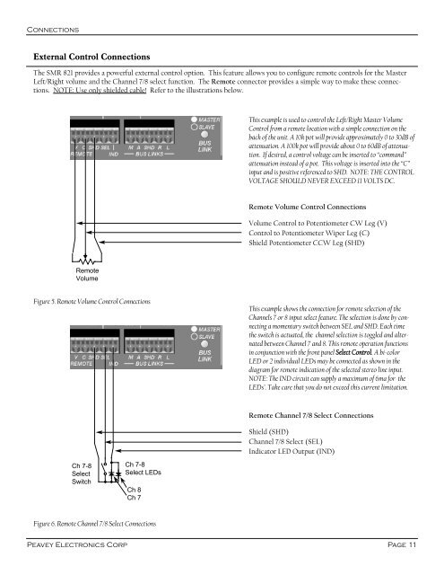
External Control Connections<br />
The SMR 821 provides a powerful external control option. This feature allows you to configure remote controls for the Master<br />
Left/Right volume and the Channel 7/8 select function. The Remote connector provides a simple way to make these connections.<br />
NOTE: Use only shielded cable! Refer to the illustrations below.<br />
This example is used to control the Left/Right Master Volume<br />
Control from a remote location with a simple connection on the<br />
back of the unit. A 10k pot will provide approximately 0 to 30dB of<br />
attenuation. A 100k pot will provide about 0 to 60dB of attenuation.<br />
If desired, a control voltage can be inserted to “<strong>com</strong>mand”<br />
attenuation instead of a pot. This voltage is inserted into the “C”<br />
input and is positive referenced to SHD. NOTE: THE CONTROL<br />
VOLTAGE SHOULD NEVER EXCEED 11 VOLTS DC.<br />
Remote Volume Control Connections<br />
Volume Control to Potentiometer CW Leg (V)<br />
Control to Potentiometer Wiper Leg (C)<br />
Shield Potentiometer CCW Leg (SHD)<br />
Remote<br />
Volume<br />
Figure 5. Remote Volume Control Connections<br />
This example shows the connection for remote selection of the<br />
Channels 7 or 8 input select feature. The selection is done by connecting<br />
a momentary switch between SEL and SHD. Each time<br />
the switch is actuated, the channel selection is toggled and alternated<br />
between Channel 7 and 8. This remote operation functions<br />
in conjunction with the front panel Select Control. A bi-color<br />
LED or 2 individual LEDs may be connected as shown in the<br />
diagram for remote indication of the selected stereo line input.<br />
NOTE: The IND circuit can supply a maximum of 6ma for the<br />
LEDs’. Take care that you do not exceed this current limitation.<br />
Remote Channel 7/8 Select Connections<br />
Shield (SHD)<br />
Channel 7/8 Select (SEL)<br />
Indicator LED Output (IND)<br />
Ch 7-8<br />
Select<br />
Switch<br />
Ch 7-8<br />
Select LEDs<br />
Ch 8<br />
Ch 7<br />
Figure 6. Remote Channel 7/8 Select Connections<br />
<strong>Peavey</strong> Electronics Corp<br />
Page 11