Test Fixtures - Feinmetall GmbH
Test Fixtures - Feinmetall GmbH
Test Fixtures - Feinmetall GmbH

You also want an ePaper? Increase the reach of your titles
YUMPU automatically turns print PDFs into web optimized ePapers that Google loves.
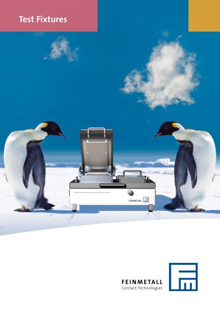
<strong>Test</strong> <strong>Fixtures</strong><br />
FEINMETALL<br />
Contact Technologies
2<br />
<strong>Test</strong> fixtures from<br />
FEINMETALL<br />
Competence and precision<br />
FEINMETALL is your competent partner<br />
for reliable contacting of electronic<br />
devices. Substantial know-how<br />
in precision technology and micromechanics,<br />
permanent and successful<br />
product innovation, competence<br />
in the manufacturing processes and<br />
a distinctive awareness of quality<br />
management are contributing to<br />
FEINMETALL success as a leading<br />
supplier in test engineering.<br />
ence. On the one side test requirements<br />
are very individual, on the other<br />
side a high operational reliability and<br />
at the same time a short implementation<br />
time are important success<br />
factors. The engineers and technicians<br />
at FEINMETALL are ideally positioned<br />
for these requirements and prepared<br />
to give you an optimum of support.<br />
Wide product portfolio<br />
Contact probes and<br />
fixtures from one source<br />
FEINMETALL offers a wide range<br />
of spring contact probes, covering a<br />
lot of innovative solutions for<br />
various applications. As an example,<br />
FEINMETALL has developed a very<br />
successful probe series for contacting<br />
lead-free soldering pads. Also, different<br />
probes with integrated functions<br />
enable clever contacting solutions for<br />
many test challenges. You can find a<br />
complete overview of our contact<br />
probe portfolio in the respective<br />
catalogue “Spring Contact Probes”.<br />
Clever concepts and system components,<br />
the use of state-of-the-art CAD<br />
tools as well as consequent documentation<br />
of the projects assure satisfied<br />
customers.<br />
The development and manufacturing<br />
of spring contact probes, test fixtures<br />
and wafer probe cards in one company<br />
are building a large basis of competence<br />
in the field of micromechanics.<br />
This combination is unique at the<br />
market and provides great advantages<br />
for developing fixtures.<br />
FEINMETALL test fixtures<br />
The development and manufacturing<br />
of test fixtures demand a high level<br />
of competence, flexibility and experi-<br />
A great in-house production depth,<br />
semi-automated processes and<br />
high-tech assembly areas are leading<br />
to constantly high quality of our test<br />
fixtures.
Quality and customer service<br />
Competent technical consultation, prompt preparation<br />
of quotations and timely realization of projects are<br />
most important to FEINMETALL. Established processes<br />
and a fully developed quality management system are<br />
facilitating this goal.<br />
Consequent quality management<br />
FEINMETALL is certified according to DIN ISO 9001, the<br />
product division contact probes additionally according<br />
to the automotive standard VDA 6.1. By consequent and<br />
continuous improvement of our processes we permanently<br />
keep up to date.<br />
Stress tests<br />
By conducting stress tests the mechanical load of a<br />
board can be determined. These tests are done either in<br />
practice by using strain gauges or by using a simulation<br />
based on the Finite Element Method (FEM). Stress tests<br />
make sure that printed circuit boards or single components<br />
are not too heavily loaded or even damaged in the<br />
fixtures. You will find further details on page 34.<br />
Table of contents<br />
Competence and quality 2<br />
Solutions for your testing tasks 4<br />
Minimum distances 5<br />
Mechanical fixtures<br />
Compact fixture 6<br />
ME-Series 8<br />
MEW-Series10<br />
WKM-Series11<br />
Vacuum fixtures<br />
Vacuum fixture kit 12<br />
<strong>Fixtures</strong> for test system<br />
Teradyne 14<br />
Digitaltest 16<br />
Aeroflex 17<br />
<strong>Fixtures</strong> with Pylon interface 18<br />
Agilent 19<br />
Spea 20<br />
Vacuum interchangeable kit 21<br />
Pylon receiver 22<br />
Finepitch fixture with rigid probes 23<br />
Solutions for dual stage fixtures 24<br />
Inline test fixtures 25<br />
Special solutions<br />
Drawer fixtures 26<br />
Revolving plate fixtures 27<br />
Customer specific fixtures 28<br />
Manual plug connectors 29<br />
Battery and accumulator test 30<br />
<strong>Fixtures</strong> for multimedia functional tests 31<br />
Contacting solar cells 32<br />
LED and optical tests 33<br />
Stress analysis 34<br />
<strong>Test</strong> heads and test sockets 35<br />
Accessories<br />
Side access units 36<br />
Interface contact blocks 37<br />
Replacement accessories 38<br />
3
4<br />
<strong>Test</strong>ing tasks<br />
Solutions for your testing tasks<br />
Selection of fixture types<br />
depending on test strategy<br />
The selection of suitable fixtures is<br />
depending on the test strategy and<br />
the test depth. For some applications<br />
a simple functional test with few test<br />
points is sufficient. For PCBs with expensive<br />
components or for security<br />
relevant applicatons in-circuit tests<br />
are necessary, that enable a location<br />
of defects at component level.<br />
Mechanical fixtures<br />
For research and development or for<br />
manufacturing of small batches simple<br />
mechanical fixures are the best<br />
choice. They need to be chosen depending<br />
on three aspects:<br />
1. The useable surface needs to be<br />
sufficient for holding the device<br />
under test.<br />
2. The housing needs to be<br />
large enough to carry necessary<br />
additional electronics.<br />
3. The force needs to be strong<br />
enough to realize the necessary<br />
number of test points.<br />
Vacuum fixtures<br />
For large volume production and finalized<br />
board layouts the use of tester<br />
specific vacuum fixures is common.<br />
These fixures enable high forces and<br />
high amounts of test points. Especially<br />
in combination with vacuum-tight<br />
boards the mechanical load is very<br />
consistent and smooth. <strong>Test</strong>ing non<br />
vacuum-tight boards is realized by using<br />
separate vacuum hoods.<br />
Contacting from<br />
top and from the side<br />
Printed circuit boards are usually<br />
contacted at the solder side. If needed,<br />
boards can also be contacted<br />
from the top at the component side.<br />
The test signals are transferred into<br />
the lower part oft the fixure (e.g. to<br />
the tester-interface) then. Accessing<br />
the board from the side is necessary<br />
if interfaces or connectors at the<br />
board need to be connected. These<br />
contacts are realized with various<br />
kinds of side access units. You will<br />
find further details on page 36.<br />
Operation of keys or switches<br />
In test fixutures, keys or switches at<br />
the component side of the board are<br />
activated pneumatically or manually.<br />
These solutions are depending on the<br />
conditions of the device under test<br />
and therefore they are realized<br />
individually and customer related.<br />
ICT and FCT in one fixture<br />
For realizing an in-circuit test and a<br />
following functional test in one test<br />
fixture, two different<br />
travels of the fixture<br />
need to be realized. For<br />
the in-circuit test all<br />
probes in the fixture<br />
need to contact the board. For the<br />
functional test with a reduced travel<br />
only the long travel probes are contacting<br />
the board. The two different<br />
travels of the fixture are realized mechanically<br />
by a shifting plate. You will<br />
find further details on page 24.<br />
Contacting of<br />
leadfree soldered pads<br />
Contacting leadfree soldered pads<br />
often leads to problems. Sticky flux<br />
residues are hard to penetrate and<br />
lead to strong contamination<br />
of common contact<br />
probes. FEINMETALL<br />
has developed a special<br />
series of contact probes<br />
for these applications. Probes of the<br />
“Progressive Series” can penetrate<br />
flux residues or other contaminated<br />
surfaces better than common probes<br />
and at the same time they are less<br />
sensitive to contamination. You will<br />
find further details in our catalogue<br />
“Spring Contact Probes”.<br />
LED-<strong>Test</strong> and optical inspection<br />
For the optical inspection of boards<br />
various solutions<br />
are available. Starting<br />
with simple<br />
optical sensors,<br />
leading to special LED-analysers or<br />
even to integrated camera systems –<br />
the selection of the most effective<br />
and economic solution is depending<br />
on the customer needs. You will find<br />
further details on page 33.<br />
Finepitch applications<br />
Fine structures are tested most effectively<br />
and most economically by using<br />
test fixtures with rigid probes. At<br />
these fixtures the fine pitch of the<br />
unit under test is<br />
transferred into a<br />
standard pitch by<br />
tangential deviation<br />
of the rigid probes<br />
up to 6 degree. With this principle<br />
centers down to 30 mil, partially even<br />
down to 20 mil, are possible. You will<br />
find further details on page 23.
Minimum distances and minimum test point sizes<br />
Each test fixture implies various tolerances<br />
resulting in a deviation from<br />
optimum positions. For this reason,<br />
there are practical limits regarding the<br />
minumum test point sizes and minimum<br />
distances between test points<br />
and components of the tested board.<br />
Here is an overview of some typical<br />
values:<br />
Centering hole<br />
Component<br />
<strong>Test</strong> point<br />
Minimum distance test point – test point<br />
by center mm mil Dimension<br />
100 mil 2,05 81<br />
75 mil 1,70 67 A<br />
50 mil 1,27 50<br />
Minimum distance test point – component Component height < 3 mm Component height > 3 mm Dimension<br />
mm mil mm mil<br />
100 mil 0,85 33 1,24 49<br />
75 mil 0,72 28 1,05 41 B<br />
50 mil 0,65 26 0,93 36<br />
Further minimum distances mm mil note Dimension<br />
and minimum sizes<br />
Centering hole diameter tolerance +0,1 / -0,05 +4 / -2 TP ≥ 0,8<br />
±0,05 ±2 TP < 0,8<br />
C<br />
<strong>Test</strong> point – centering hole 1,0 40 D<br />
<strong>Test</strong> point – board edge 0,3 12<br />
3 119 with mold<br />
E<br />
<strong>Test</strong> point size > 0,8 32 without guiding plate<br />
> 0,7 28 with guiding plate F<br />
> 0,4 16 rigid probe<br />
Tolerance of board contour ±0,25 ±10 positioning by pilot pin<br />
±0,1 ±4 positioning by board contour<br />
The stated minimum test point size can only be realized at optimum conditions. Tolerances e.g. of the<br />
centering holes on the board may cause further limitations. Additional restrictions may depend on the<br />
choice of tip style and tip size of the spring contact probes.<br />
Minimum distances and sizes for fixtures with rigid probes see page 23.<br />
5
6<br />
Mechanical <strong>Fixtures</strong><br />
Compact fixture<br />
The robust compact fixtures are suitable<br />
for the test of single boards or small<br />
batches, e.g. in research and development<br />
labs. The exact vertical travel guarantees<br />
a precise contact even at small centers.<br />
Compact fixures are available with interchangeable<br />
cassette or alternatively as<br />
stand-alone device.<br />
→ compact and robust design<br />
→ ergonomic handle adjustable<br />
→ ball bearing guides<br />
→ dual access probing possible<br />
→ cost efficiency due to interchangeable cassette<br />
→ linear vertical travel: max. 8 mm<br />
→ force: max. 150 N (e.g. for 75 probes of 2 N each)<br />
Outer dimensions Inner dimensions DUT space Order Code<br />
(WxDxH in mm) (WxDxH in mm) (WxD in mm)<br />
Handle mechanics for interchangeable<br />
cassettes 180 x 150 x 230 * 43051706<br />
Interchangeable cassette small 180 x 180 x 70 155 x 155 x 50 130 x 140 43051702<br />
Interchangeable cassette large 280 x 180 x 70 255 x 155 x 50 230 x 140 43051704<br />
Compact fixture (stand-alone) 180 x 300 x 230 155 x 155 x 50 130 x 140 43051700<br />
Further sizes on request.<br />
* fixture closed, contacted<br />
The size of the stand-alone<br />
version is the same as the size<br />
of the handle mechanics<br />
with small cassette.
Compact fixture with<br />
interface to a test system<br />
For testing single boards or small batches with<br />
an existing test system (e.g. Agilent 3070) the<br />
compact fixture mechanics can be mounted on<br />
a tester interface. This solution allows the use<br />
of small and large interchangeable cassettes in<br />
combination with existing test systems.<br />
→ handle mechanics mounted on tester interface (e.g. Agilent 3070)<br />
→ use of small and large interchangeable cassette possible<br />
→ maximum 255 test points<br />
→ intermediate interface designed for three interface blocks (85-pole)<br />
→ interface realized with contact probes in the fixture and interface pins in the cassettes<br />
→ further options on request (e.g. signal conditioner board for test jet applications etc.)<br />
Compact fixture for larger<br />
boards and higher forces<br />
A stronger design with two combined handle<br />
mechanics allows a higher number of test<br />
points and a test of larger boards. The integrated<br />
interchangeable cassette is brought into the<br />
correct position by twisting an eccentric and<br />
can be changed simply. The internal connection<br />
between cassette and fixture housing is realized<br />
by pylon interface blocks with maximum 340<br />
interconnection points.<br />
→ maximum force 450 N<br />
→ maximum 340 test points<br />
→ adaption to all FEINMETALL-housings possible<br />
→ modular design allows adaption to all common interfaces<br />
→ interface realized with contact probes in the fixture and<br />
interface pins in the cassette<br />
→ further options on request (e.g. HV-protected, lightproof etc.)<br />
7
8<br />
Mechanical <strong>Fixtures</strong><br />
Mechanical fixture<br />
ME-Series, 600 N<br />
The mechanical fixtures of the ME series<br />
are suitable for functional test, end test or<br />
small ICT-applications up to 300 probes.<br />
The ME series is available fully fitted and<br />
completely wired, partly fitted or as a kit<br />
for own assembly.<br />
→ universal mechanical fixture<br />
→ available in three sizes (size A, B, C)<br />
→ linear motion travel 17 mm<br />
→ dual access probing possible<br />
→ maximum force 600 N (e.g. 300 probes of 2 N each)<br />
→ 20 pushers included in delivery<br />
→ optional for 230 V applications<br />
Possible DUT sizes:<br />
ME1A ME1B ME1C<br />
Description<br />
Fixture size A<br />
Fixture size B<br />
Fixture size C<br />
Order Code<br />
ME1A<br />
ME1B<br />
ME1C<br />
Larger housings on request.
Housing variants for ME- and MEW-Series<br />
Standard housing for ME1A, ME1B, MEWG-A<br />
Higher housing for ME1A, ME1B, MEWG-A<br />
Standard housing for ME1C, MEWG-B<br />
Higher housing for ME1C, MEWG-B<br />
The housings can be combined with various interfaces (e.g. Virginia, Pylon, all common ICT interfaces).<br />
Further sizes and housings prepared for various test systems on request.<br />
9
10<br />
Mechanical <strong>Fixtures</strong><br />
Mechanical fixture with<br />
interchangeable cassettes<br />
MEW-Series up to 600 N<br />
The mechanical fixtures of the MEW-series<br />
are suitable for functional test, end test or<br />
small ICT applications up to 300 probes.<br />
The interchangeable cassettes provide an<br />
excelent cost efficiency. Additional electronic<br />
or pneumatic components can be integrated in<br />
the housing. (Housing dimensions see page 9.)<br />
→ dual probing as well as lateral probing possible<br />
→ robust cassette interface with 480 pins<br />
→ simple opening and closing by gas strut<br />
→ removable rear-panel (e.g. for connector mounting)<br />
→ for max 300 contact probes of 2 N each<br />
Possible DUT sizes:<br />
MEWG-A<br />
MEWG-B<br />
Description<br />
Fixture size A<br />
Fixture size B<br />
Interchangeable cassette for MEWG-A<br />
Interchangeable cassette for MEWG-B<br />
Order Code<br />
MEWG-A<br />
MEWG-B<br />
MEWK-A<br />
MEWK-B<br />
Larger housings and 19’’ variants on request.
Mechanical fixture with<br />
interchangeable cassettes<br />
WKM-Series up to 900 N<br />
The mechanical fixtures of the WKM-series<br />
are suitable for ICT and functional test up to<br />
450 probes.<br />
It can be used for all common test systems<br />
and provides a very cost effective solution<br />
due to the interchangeable cassettes.<br />
→ robust cassette interface realized with spring contact probes<br />
→ maximum 840 transfer pins<br />
→ maximum 450 probes of 2 N spring force each<br />
→ linear motion travel of 12 mm<br />
→ removable rear panel for connector mounting<br />
Possible DUT sizes:<br />
WKM1A<br />
WKM1B<br />
Description<br />
Fixture size A<br />
Fixture size B<br />
Interchangeable cassette for WKM1A<br />
Interchangeable cassette for WKM1B<br />
Interchangeable cassette as WKM2A<br />
but without top plate<br />
Interchangeable cassette as WKM2B<br />
but without top plate<br />
Order Code<br />
WKM1A<br />
WKM1B<br />
WKM2A<br />
WKM2B<br />
WKM3A<br />
WKM3B<br />
11
12<br />
Vacuum-<strong>Fixtures</strong><br />
Vacuum interchangeable kit<br />
The ICT vacuum fixtures from FEINMETALL are based on the basic kit for each test system and can contain several<br />
special functions.<br />
The vaccum kit consists of the housing and the vacuum cassette. The housing carries the vacuum cassette, contains the<br />
wiring and has an interface depending on the manufacturer. The vacuum cassette consists of the probe plate and the<br />
top plate. Contact probes of the probe plate contact the DUT and may be guided by drilles in the top plate if applicable.<br />
Options:<br />
e.g. Dual stage contacting<br />
from top<br />
Vacuum cassette<br />
Top plate<br />
Probe plate<br />
Vacuum sealing<br />
Security blocker<br />
Positioner<br />
Housing<br />
Vacuum connection<br />
Interface depending<br />
on the test system<br />
Space for customer<br />
specific expansions<br />
Dual stage test<br />
FEINMETALL vacuum cassette can get furnished with a dual stage sealing. A combined in-circuit- and functional test can<br />
be made in one fixture. The shifting plate technology allows two testing levels, one for ICT and one for FCT. Further details<br />
on page 24.
Options for vacuum cassettes<br />
For vacuum cassettes several options are available (independent from test system)<br />
Mold:<br />
<strong>Test</strong>ing of vacuum-tight boards<br />
Vacuum hood:<br />
<strong>Test</strong>ing of boards from one side, seald by<br />
a vacuum-tight hold-down system (shown here<br />
as tandem version)<br />
Vacuum hood with contacting from top:<br />
Contacting boards from both sides<br />
Vacuum hood with dual stage contacting from top:<br />
Contacting from both sides for functional- and in-circuit-test<br />
Manual hold-down system with vacuum-free zone:<br />
The board is placed in the vacuum-free zone and is hold<br />
down by a manual hold-down-system (no figure).<br />
13
14<br />
Vacuum-<strong>Fixtures</strong><br />
ICT fixture for<br />
Teradyne test system<br />
→ SPECTRUM 885x<br />
The vacuum housing kit contains the<br />
housing and the vacuum cassette.<br />
FEINMETALL provides customer specific<br />
fixture development. Alternatively the<br />
kit can be delivered for own assembly.<br />
In this case the dual stage cassette is<br />
delivered with dual stage sealing and<br />
without shifting plate. Shifting plates and<br />
further assembly materials on request.<br />
Housing kit Order Code DUT size Dimensions<br />
(WxD in mm)<br />
(WxD in mm)<br />
Housing kit for SPECTRUM 885x small 1 stage 40220001 395 x 315 536 x 452<br />
Housing kit for SPECTRUM 885x small 2 stages 40220002 395 x 315 536 x 452<br />
Further kit sizes for medium and large (2560 test points) and Tandem device on request<br />
Interface Order Code Number of Pins<br />
Interface SPECTRUM 885x 4022SS1280 1280<br />
Options Order Code DUT size<br />
(WxD in mm)<br />
Vacuum hood 40301066 350 x 365<br />
Contacting from top 40300852 250 x 305 or 285 x 265<br />
Dual stage contacting from top 40301341 290 x 265
ICT fixture for<br />
Teradyne test systems<br />
→ GENRAD 228x<br />
The vacuum housing kit contains the<br />
housing and the vacuum cassette.<br />
FEINMETALL provides customer specific<br />
fixture development. Alternatively the<br />
kit can be delivered for own assembly.<br />
In this case the dual stage cassette is<br />
delivered with dual stage sealing and<br />
without shifting plate. Shifting plates and<br />
further assembly materials on request.<br />
Housing kit Order Code DUT size Dimensions<br />
(WxD in mm)<br />
(WxD in mm)<br />
Housing kit for GENRAD 228x small 1 stage 40200001 450 x 335 575 x 437<br />
Housing kit for GENRAD 228x small 2 stages 40200002 450 x 335 575 x 437<br />
Tandem solution and large version on request<br />
Interface small Order Code Number of Pins Loaded Slots<br />
Interface GR228x 512 4020SS0512 512 2 - 7<br />
Interface GR228x 1024 4020SS1024 1024 2 - 11<br />
Interface GR228x 1536 4020SS1536 1536 2 - 15<br />
Interface GR228x 1920 4020SS1920 1920 2 - 18<br />
Power pin GR228x 2101526<br />
The interfaces are completely drilled (Slot O-18). Power-Pins (Slot O) are unloaded.<br />
Additional wiring: Slot 2 and 3<br />
<strong>Test</strong> point wiring: Slot 4-18<br />
Options Order Code DUT size<br />
(WxD in mm)<br />
Vacuum hood 40301064 410 x 350<br />
Contacting from top 40300850 310 x 290 or 340 x 250<br />
Dual stage contacting from top 40301339 340 x 250<br />
15
16<br />
Vacuum-<strong>Fixtures</strong><br />
ICT fixture for<br />
Digitaltest test systems<br />
→ MTS 300<br />
The vacuum housing kit contains the<br />
housing and the vacuum cassette.<br />
FEINMETALL provides customer specific<br />
fixture development. Alternatively the<br />
kit can be delivered for own assembly.<br />
In this case the dual stage cassette is<br />
delivered with dual stage sealing and<br />
without shifting plate. Shifting plates and<br />
further assembly materials on request.<br />
Housing kit Order Code DUT size Dimensions<br />
(WxD in mm)<br />
(WxD in mm)<br />
Housing kit for MTS 300 1 stage 40210001 385 x 400 594 x 545<br />
Housing kit for MTS 300 2 stages 40210002 385 x 400 594 x 545<br />
Housing kit for MTS 300 Tandem 1 stage 40210001T 160 x 355 594 x 545<br />
Housing kit for MTS 300 Tandem 2 stages 40210002T 160 x 355 594 x 545<br />
Interface<br />
Interface MTS 300, blank<br />
Interfacepin<br />
Order Code<br />
4021SS0000<br />
I-Z1<br />
Options Order Code DUT size<br />
(WxD in mm)<br />
Vacuum hood 40301067 350 x 415<br />
Contacting from top 40300853 250 x 355 or 285 x 315<br />
Dual stage contacting from top 40301342 290 x 315<br />
Vacuum hood Tandem 40301068 135 x 350<br />
Contacting from top Tandem 40300854 90 x 255
ICT fixture for<br />
Aeroflex test systems<br />
→ MC 4200<br />
The vacuum housing kit contains the<br />
housing and the vacuum cassette.<br />
FEINMETALL provides customer specific<br />
fixture development. Alternatively the<br />
kit can be delivered for own assembly.<br />
In this case the dual stage cassette is<br />
delivered with dual stage sealing and<br />
without shifting plate. Shifting plates and<br />
further assembly materials on request.<br />
Housing kit Order Code DUT size Dimensions<br />
(WxD in mm)<br />
(WxD in mm)<br />
Housing kit for MC 4200 1 stage 40250001 385 x 400 531 x 525<br />
Housing kit for MC 4200 2 stages 40250002 385 x 400 531 x 525<br />
Housing kit for MC 4200 Tandem 1 stage 40250001T 160 x 355 531 x 525<br />
Housing kit for MC 4200 Tandem 2 stages 40250002T 160 x 355 531 x 525<br />
Interface<br />
Interface MC 4200, blank<br />
Interfacepin<br />
Order Code<br />
4025SS0000<br />
I-G1<br />
Options Order Code DUT size<br />
(WxD in mm)<br />
Vacuum hood 40301067 350 x 415<br />
Contacting from top 40300853 250 x 355 or 285 x 315<br />
Dual stage contacting from top 40301342 290 x 315<br />
Vacuum hood Tandem 40301068 135 x 350<br />
Contacting from top Tandem 40300854 90 x 255<br />
17
18<br />
Vacuum-<strong>Fixtures</strong><br />
ICT fixture for<br />
test systems based<br />
on Pylon interfaces<br />
Compatible to<br />
→ Dr. Eschke<br />
→ Rhode & Schwarz<br />
→ ITA Scorpion<br />
→ TERADYNE GENRAD 2270/71<br />
The vacuum housing kit contains the<br />
housing and the vacuum cassette.<br />
FEINMETALL provides customer specific<br />
fixture development. Alternatively the<br />
kit can be delivered for own assembly.<br />
In this case the dual stage cassette is<br />
delivered with dual stage sealing and<br />
without shifting plate. Shifting plates and<br />
further assembly materials on request.<br />
Suitable interface-blocks can be found on page 37.<br />
Housing kit Order Code DUT size Dimensions<br />
(WxD in mm)<br />
(WxD in mm)<br />
Housing kit with Pylon interface 1 stage 40240001 395 x 315 539 x 468<br />
Housing kit with Pylon interface 2 stages 40240002 395 x 315 539 x 468<br />
Options Order Code DUT size<br />
(WxD in mm)<br />
Vacuum hood 40301066 350 x 365<br />
Contacting from top 40300852 250 x 305 or 285 x 265<br />
Dual stage contacting from top 40301341 290 x 265
ICT fixture for<br />
Agilent test systems<br />
→ AGILENT I 5000<br />
→ AGILENT 3070<br />
The vacuum housing kit contains the<br />
housing and the vacuum cassette.<br />
FEINMETALL provides customer specific<br />
fixture development. Alternatively the<br />
kit can be delivered for own assembly.<br />
In this case the dual stage cassette is<br />
delivered with dual stage sealing and<br />
without shifting plate. Shifting plates and<br />
further assembly materials on request.<br />
Housing kit Order Code DUT size Dimensions<br />
(WxD in mm)<br />
(WxD in mm)<br />
Vacuum-<strong>Fixtures</strong> 3070 small 4112260 310 x 390 475 x 464<br />
Vacuum-<strong>Fixtures</strong> 3070 small, Tandem 4112260DW 135 x 390 475 x 464<br />
Vacuum-<strong>Fixtures</strong> 3070 large 4112263 700 x 390 855 x 464<br />
Vacuum-<strong>Fixtures</strong> 3070 large, Tandem 4112253DW 310 x 390 855 x 464<br />
Interface<br />
Order Code<br />
Personality Pin 2100128<br />
Options Order Code DUT size<br />
for 3070 small<br />
(WxD in mm)<br />
Vacuum hood 40300985 330 x 400<br />
Contacting from top 4112270 225 x 340 or 265 x 300<br />
Dual stage contacting from top 40301338 265 x 295<br />
Vacuum hood Tandem 40301051 135 x 355<br />
Options for 3070 large on request.<br />
19
20<br />
Vacuum-<strong>Fixtures</strong><br />
ICT fixture for<br />
SPEA test systems<br />
→ SPEA 3030<br />
The vacuum housing kit contains the<br />
housing top plate und the completely<br />
drilled, unloaded interface. The interface<br />
can get loaded with Wire-Wrap connectors.<br />
The hold-down plate is available in<br />
two material versions.<br />
Housing kit Order Code DUT size Dimensions<br />
(WxD in mm)<br />
(WxD in mm)<br />
Housing kit SPEA 3030 40350409-01 510 x 386 620 x 560<br />
Hold-down plate, transparent ESD 40350409-002 460 x 330 530 x 330<br />
Hold-down plate made of FR4 40350409-100 460 x 330 530 x 330<br />
Wire-Wrap connector (72-pole) 2102002<br />
→ SPEA UNI 500 (BZIF)<br />
The vacuum housing kit contains the<br />
housing, the vacuum cassette and an<br />
unloaded interface. The interface can<br />
get loaded with Wire-Wrap connectors.<br />
Housing kit Order Code DUT size Dimensions<br />
(WxD in mm)<br />
(WxD in mm)<br />
Housing kit SPEA UNI 500 (BZIF) 40260001 340 x 330 488 x 586<br />
Housing kit oversize SPEA UNI 500 (BZIF) 40260003 350 x 430 488 x 672<br />
Wire-Wrap connector (72-pole) 2100895<br />
Options (vacuum hood, etc.) on request.
Universal vacuum<br />
interchangeable kit<br />
→ Teradyne<br />
→ Digitaltest<br />
→ AEROFLEX<br />
→ and others<br />
Receiver<br />
→ cost efficient system with interchangeable cassettes<br />
→ easy handling<br />
→ cassette-interface easily accessible<br />
→ two interface options: 840 test points or 1300 test points<br />
Interchangeable cassette<br />
→ two board sizes: Double European size or 470x330mm<br />
→ dual stage version possible<br />
→ small space required for exchange cassettes<br />
→ cassettes are applicable independently from test system<br />
→ specific versions according to application with mold, vacuum-hood<br />
with top-probing, hold-down gate with vacuum-free area<br />
Description Order Code DUT size Dimensions*<br />
(WxD in mm) (WxDxH in mm)<br />
Basic device, max. 840 test points 1 WK2001 310x230 600x600x120<br />
Basic device, max. 1300 test points 1 WK4001 470x330 600x600x120<br />
Interchangeable cassette, max. 840 test points WK1001 310x230 380x310x90<br />
Interchangeable cassette, max. 1300 test points WK3001 470x330 540x410x90<br />
1 Information about test system is required * depending on test system<br />
21
22<br />
Vacuum-<strong>Fixtures</strong><br />
Pylon-Receiver<br />
4<br />
3<br />
The Pylon-Receiver is a modular test<br />
concept for interchangeable vacuum<br />
cassettes with a modular configuration<br />
of different fixture steps. Initially the<br />
interface-receiver serves as a connection<br />
or assembly of any random individual<br />
electronic measuring equipment. This is<br />
docked at the interchangeable cassette<br />
receiver over a prevalent Pylon-interface.<br />
This assimilates, in turn, a normal<br />
interchangeable vacuum cassette. The<br />
contacting of these interchangeable<br />
cassettes is realised by interface blocks<br />
with spring contact probes, which again<br />
guarantee a long-lasting and error-free<br />
contacting even at frequent change of<br />
cassettes. The complete solution allows<br />
the realisation of a cost-efficient, modular<br />
and individual in-circuit or functional<br />
test for boards.<br />
2<br />
The configuration of the Pylon-Receiver has the following modules:<br />
1 Interface-receiver with Pylon-interface (170-terminal interface blocks<br />
with spring contact probes) with the possibility of further integration<br />
of electronic measuring equipment<br />
2 Interchangeable cassette receiver with Pylon-Interface (Interface pins)<br />
and an internal interface with spring contact probes for the interchangeable<br />
vacuum cassette.<br />
3 internal interface comprising of six 96-terminal spring contact probes<br />
interface beam.<br />
4 Interchangeable vacuum cassette with an active area of 220mm x<br />
200mm and an interface with 96-terminal VG connector strip.<br />
1<br />
Naturally, all existing FEINMETALL fixture solutions (vacuum and mechanical<br />
fixtures, with or without interchangeable cassettes) can be docked at the<br />
Pylon-Receiver with the appropriate Pylon-interface (e.g. Teradyne/GR2270/71,<br />
ITA Scorpion, Rhode&Schwarz TSI/TSA).<br />
Description<br />
Order Code<br />
Interface-Receiver 19“ rack (1) 4-42000238<br />
Interchangeable cassette receiver (2) 40300591<br />
VG-Connector with spring contact probes (3) 43050258<br />
Vacuum interchangeable cassette (4) 40300423<br />
Smaller receiver version on request.
Finepitch fixture<br />
with rigid probes<br />
For various test systems<br />
→ agilent<br />
→ Teradyne<br />
→ Digitaltest<br />
→ spea<br />
→ aeroflex<br />
→ and others<br />
At test fixtures with rigid probes, the<br />
fine pitch of the DUT is transferred to a<br />
standard pitch of 2,54 mm. This is realised<br />
by tangential deviation of the rigid<br />
probes up to 6 degree.<br />
The rigid probe test head is assembled on<br />
top of any standard vacuum fixture kit<br />
and is applicable for all test systems.<br />
Special features<br />
→ fine pitch down to 30 mil, feasible for larger area<br />
→ easy replacement of rigid probes<br />
→ contacting via vacuum hood<br />
→ cost efficient for large number of test points with centers ≤50mil<br />
→ for wired component contacting rigid probes with tip style 06<br />
(Serrated Head) and 14 (4-Point Crown Head) are available.<br />
→ possible to contact on both sides<br />
→ special data generation for Agilent 3070 possible<br />
Finepitch-Fixture (0,3 mm needles)<br />
Minimum distance mm mil Recommended Dimension*<br />
<strong>Test</strong> point - test point 0,50 20 A<br />
<strong>Test</strong> point - component (smaller 3 mm) 0,50 20 min 0,8 mm B<br />
<strong>Test</strong> point - component (higher 3 mm) 0,76 30 B<br />
Diameter centering hole tolerance ±0,05 ±2<br />
<strong>Test</strong> point - centering hole 0,50 ±0,03 20 min 0,8 mm D<br />
<strong>Test</strong> point to board edge 0,3 12 E<br />
Minimum test point size 0,35 14 F<br />
Finepitch-Fixture (0,5 mm needles)<br />
Minimum distance mm mil Recommended Dimension*<br />
<strong>Test</strong> point - test point 0,76 30 A<br />
<strong>Test</strong> point - component (smaller 3 mm) 0,76 30 min 1,0 mm B<br />
<strong>Test</strong> point - component (higher 3 mm) 1,0 40 B<br />
Diameter centering hole tolerance ±0,05 ±2<br />
<strong>Test</strong> point - centering hole 0,76 ±0,05 30 min 1,0 mm D<br />
<strong>Test</strong> point - board edge 0,3 12 E<br />
Minimum test point size 0,4 15 0,6 F<br />
* see drawing on page 5<br />
23
24<br />
Vacuum-<strong>Fixtures</strong><br />
Dual stage contacting for combined ICT and functional test<br />
Dual stage fixtures are used for combining an in-circuit test<br />
and a functional test in one test fixture. For the in-circuit<br />
test the board is contacted by all spring contact probes. Due<br />
to a reduced travel of the following functional test only<br />
the long travel probes are contacting the DUT. The different<br />
travels are realized by shifting plates.<br />
Shifting plate enables<br />
different travels<br />
Shifting actuator<br />
ICT contacting<br />
Dual stage contacting from top<br />
A dual stage contacting is also possible from the top side<br />
of the board. This mechanically sophisticated solution is<br />
realized by a clever design of the shifting plate and allows<br />
different travels even at limited space.<br />
FCT contacting<br />
ICT-Probes<br />
(do not contact during<br />
functional test)<br />
Height proportions and contact probe selection for dual stage fixtures<br />
Combination of probes for<br />
dual stage fixtures:<br />
ICT<br />
FCT<br />
50 mil F050 F051<br />
50 mil F767 F788<br />
75 mil F075/F703 F793<br />
100 mil F100/F585 F588<br />
For realizing dual stage fixtures spring contact probes of different lengths are needed. The projection heights of the<br />
probes need to be selected in a way that for the ICT level all probes are contacting the DUT whereas for the FCT only<br />
the long travel probes are contacting the DUT. Additionally, by chosing shorter or longer versions of each probe the<br />
height differences between wired components and solder pads can be adjusted.
Inline test fixtures<br />
Inline test fixtures are used for ICT- or functional<br />
test for printed circuit boards and modules, inside<br />
of fully automated production lines. The arrangement<br />
usually is made as interchangeable-kitsystem<br />
in order to allow comfortable adjustment<br />
to different DUT‘s and to avoid downtime in case<br />
of any maintenance or probe replacement.<br />
FEINMETALL provides inline test fixtures for<br />
various test systems.<br />
Special features inline test fixtures<br />
→ double sided (top and bottom) probing possible<br />
→ minimum pitch: 50 mil<br />
→ ESD protection<br />
→ possible options: Scanner, Marker etc.<br />
Agilent 3070<br />
SPEA 3030<br />
SPEA 3030 Universal Inline-Kit<br />
25
26<br />
Special solutions<br />
Drawer fixtures<br />
With drawer fixtures two DUTs can be<br />
tested in one fixture. As long as one<br />
DUT is tested in one drawer, the other<br />
DUT can be handled. The drawers are<br />
located side by side and can be operated<br />
manualy or pneumatically.<br />
→ pneumatically driven fixture<br />
→ contacting elments exchangeable<br />
→ contacting from top, bottom and lateral possible<br />
→ drawer locked during test<br />
→ max. component height on top 19mm, at the bottom 9mm<br />
→ external interface implemented by standard connectors<br />
→ integrated PLC, communication to test system optional<br />
→ dimensions 820x820x440 mm (other dimensions on request)
Revolving plate fixture<br />
Revolving plate test fixtures enable costand<br />
time-saving ICT and functional tests of<br />
electronic devices by simultanuous handling<br />
of two DUTs. For example if a board is being<br />
tested in one half of the fixture, in the other<br />
half of the fixture a tested board can be<br />
taken out and the next one can be put into<br />
the fixture. Compared to standard fixtures<br />
this simultanuous action guarantees a higher<br />
throughput in the testing process.<br />
→ pneumatically driven fixture<br />
→ DUT space 160x100mm<br />
→ contacting element changeable<br />
→ optional contacting from top and from the side<br />
→ maximum component height 35mm top side<br />
and 16mm bottom side<br />
→ external interface realized in various connector standards<br />
→ optional with tester interface<br />
→ optional integrated PLC<br />
→ light curtain as safety element<br />
Revolving plate fixture (4-fold)<br />
A revolving plate fixture for holding four DUTs enables the execution of<br />
four sequential test-steps in one fixture.<br />
→<br />
→<br />
→<br />
→<br />
→<br />
pneumatically driven<br />
large rear panel for service needs<br />
contacting elements changeable<br />
light curtain as safety element, emergency stop<br />
maximum DUT size Ø 135 mm<br />
Typical example for sequential test steps<br />
Station 1: insert DUT, scan barcode<br />
Station 2: contact DUT, pneumatic key activation<br />
Station 3: contact DUT, programming<br />
Station 4: remove DUT, place label<br />
27
28<br />
Special solutions<br />
Customised special fixtures<br />
Manually operated<br />
knee-lever-contacting at small pitches<br />
Fixture with open handling area for adjustment<br />
(secured by a light curtain, multisided pneumatical contacting)<br />
Our directive:<br />
FEINMETALL is committed as service provider for contacting solutions<br />
to our customers. Our strength is the implementation of customer<br />
requirements to functional and reliable products. The individual<br />
application requirements are realised at FEINMETALL as customized<br />
special fixtures.<br />
High current contacting<br />
for serial production
Manual plug connectors<br />
Customized adaptions for plug connectors<br />
For many applications in mechanical engineering and in the automotive<br />
industry electronic assemblies are equipped with customized plug connectors<br />
that are not standardized. For the functional test of these assemblies a test<br />
system needs to be connected to these individual plugs.<br />
FEINMETALL is offering manual plug connectors for these individual connectors<br />
and sockets. Spring contact probes as contact elements guarantee<br />
a good signal transmission and a smooth connection without damaging the<br />
plugs or sockets. The housing and dimensions are individually adapted to<br />
customer requirements.<br />
29
30<br />
Special solutions<br />
Formation and test of<br />
batteries and accumulator cells<br />
FEINMETALL has established a strong business with<br />
solutions for test and charge processes of batteries<br />
and accumulator cells. With our cooperation partner<br />
Digatron we have gained a high level of expertise in<br />
reliable contacting of batteries and accumulators.<br />
This is the basis for many large battery manufacturers,<br />
who are working on the automobile future.<br />
FEINMETALL fixture solutions include simple standalone<br />
fixtures as well as complex and automated<br />
systems for large scale production.<br />
Detail picture of a contacting device for large cylindric lithium cells<br />
Especially the development of High Current Kelvin Probes for charging and discharging<br />
processes during the formation of accumulator cells has contributed to FEINMETALL’s<br />
business success in this application.<br />
Digatron Firing Circuits is an international corporation<br />
developing and producing computer based test systems<br />
for all kinds of batteries and electrochemical energy<br />
storages. Besides the headquarter in Aachen, Germany,<br />
there are production plants in the USA and in China.<br />
Especially the expertise in digital controls, data acquisition<br />
and evaluation software in combination with highly<br />
dynamical power electronics up to 400 kW is outstanding<br />
at the market. Digatron customers are the large battery<br />
manufacturers as well as companies using batteries in a<br />
large scale. Also research labs of the automotive industry<br />
and universities working on new technologies for emission<br />
free drives are using Digatron test systems. With<br />
more than 40 years of experience Digatron is a worldwide<br />
market leader and has more than 200 highly qualified<br />
employees.<br />
The cooperation between Digatron and FEINMETALL has<br />
established several years ago and has grown and proved<br />
during numerous successful projects – especially in the<br />
field of lithium cells for automotive applications.<br />
Digatron site in Aachen, Germany
Functional test with optical<br />
and acoustic elements<br />
The test of complex systems with integrated optical<br />
and acoustic elements like communication systems<br />
or control elements in automotive applications is a<br />
challenging test engineering task. Very often a pure<br />
electrical or optical inspection is not sufficient. In<br />
fact integrated systems for tests with keyboards,<br />
speakers, microphohes, switches etc. are demanded<br />
to realize the test needs.<br />
For these applications we have already developed various solutions with our<br />
cooperation partner NOFFZ. One important example is the integration of a<br />
camera dome into a test fixture to realize an optical inspection of a DUT without<br />
interfering light from outside.<br />
The company NOFFZ Computer Technology provides<br />
turnkey solultions for computer based measurement and<br />
automation systems including a wide range of services.<br />
– Image processing<br />
(LED- & display test, surface analysis)<br />
– Microcontroller technology and signal conditioning<br />
– Development of electronic products and modules<br />
– Flexible limited-lot production of electronic<br />
devices, modules and interfaces<br />
– Management of product variants, tests and<br />
databases up to ERP level (Oracle, SAP)<br />
Noffz headquarter in Tönisvorst, Germany<br />
Key competences are:<br />
– Development and production of automated test systems<br />
(ATE, ICT/FCT, AOI, Audio, Video)<br />
– Development of hard- and software<br />
Due to successful cooperations with partner companies<br />
the spectrum of competence is enhanced according to<br />
customer needs and requirements. The company Noffz is<br />
acting as general contractor, system integrator and development<br />
service provider for all industry branches.<br />
The cooperation between FEINMETALL and Noffz has<br />
established several years ago and has proven its value for<br />
many satisfied customers.<br />
31
32<br />
Special solutions<br />
Contacting solar cells at flash-tests<br />
For a classification of solar cells, the cells are contacted from<br />
both sides during a standardized flash. The busbars at the<br />
top side of the cell are contacted by several probes mounted<br />
in a beam, which needs to be slim enough to avoid strong<br />
shadows and stable enough to guarantee good contacts<br />
and a long life cycle. The contact of the cells on the rear side<br />
is realized analogue to the contacting from the top but it is<br />
much less difficult, because at the bottom the solar cells are<br />
metal plated and shadows are no problem at all.<br />
Typical test setup for contacting solar cells<br />
In practice the contacting during the flash test is realized<br />
at enormous speed. About once a second, the photovoltaic<br />
cells are inserted into the tester, contacted and checked by<br />
a standardized flash of lightning. The contact bars as well<br />
as the integrated contact probes are exposed to enormous<br />
forces and vibrations. The contact beams should not deform<br />
and the probes need to provide a good electrical contact at<br />
the given contact surfaces also after many touchdowns. On<br />
the other hand, the beams should be as slim as possible to<br />
avoid strong shadows on the solar cell. These opposite requirements<br />
and developments have to be carefully considered<br />
when developing adequate solutions. Different combinations<br />
of material and shapes are precisely studied during<br />
the design phase of slim and stable contact beams either in<br />
practice or by simulation with the Finite-Element-Method<br />
(FEM).<br />
Simulation of the bending behaviour of a contact bar<br />
In this example it is clearly visible that the distortion is most extensive within the middle of the beam (red colour). However,<br />
the contact probes placed in the middle of the beam are not the most stressed ones. More critical are the probes at the end<br />
of the beam, because these are exposed to stronger lateral forces.<br />
Optical inspection with camera system „PlatiJet“<br />
For testing LEDs, for inspecting displays or 7-segment displays and generally for a verification<br />
of the correct component assembly it is possible to integrate a camera system<br />
into a test fixture. In cooperation with our partner company WG TEST we develop fixture<br />
solutions with the optical inspection system “PlatiJet”. This system includes up to eight<br />
high resolution cameras as well as the corresponding examination and analysis software<br />
and offers a great variety of test solutions.
LED-<strong>Test</strong> and optical inspection of boards<br />
Electrical test of LEDs<br />
A simple detection of false LEDs can be realized without<br />
high efforts by measuring the breakdown voltage. However,<br />
this method only allows testing the correct assembly of the<br />
LEDs. Proving the correct color is not possible because of<br />
overlaping ranges of the breakdown voltage of differently<br />
coloured LEDs.<br />
Use of „Optical Heads“<br />
Especially at tolerances of the LED position or at scattered<br />
light of neighbour LEDs it is important to use optical heads.<br />
These optical heads are focusing the light by a lens and enable<br />
exact measurements in a large tolerance range.<br />
Optical test of LEDs<br />
For testing optical characteristics of LEDs (e.g. intensity<br />
and colour) various optical sensors or camera systems of<br />
different manufacturers are available. Important is the integration<br />
of these systems into a test fixture, because each<br />
LED application results in different limitating conditions and<br />
therefore needs an individual solution.<br />
Possibilities:<br />
→ use of optical heads<br />
→ use of LED analysers<br />
→ use of camera systems<br />
Use of LED-Analysers<br />
For capturing and analyzing different LED parameters<br />
LED analysers (e.g. from Feasa) can be implemented. These<br />
analysers allow measuring the intensity, the wavelength,<br />
the colour saturation etc. of LEDs and transferring these<br />
data into the test system.<br />
Optical inspection also with integrated acoustic elements<br />
For detecting a DUT without scattering light from outside a camera dome can be<br />
integrated in a test fixture. With our partner NOFFZ we can provide complete<br />
solutions with connection to the test system and implementation of the respective<br />
analysis software. These solutions allow the integration of speakers, microphones and<br />
control elements that are needed for testing e.g. communication systems or control<br />
panels. You will find further details on page 31.<br />
33
34<br />
Special solutions<br />
Stress analysis<br />
By a comprehensive stress analysis the force effects of a test<br />
fixture on tested boards is determined.<br />
This examination can be done in practice by using strain<br />
gauges. At defined test points the limiting values defined by<br />
the customers can be approved.<br />
FEM-analysis<br />
Alternatively a stress analysis can be done already during<br />
the mechanical production. A simulation based on the Finite<br />
Element Method (FEM) allows a risk analysis of the expected<br />
force effects already in advance.<br />
Load definition of a PCB<br />
Strain gauges on a PCB<br />
In case of exceeding values the following<br />
measures can be taken:<br />
→ improvement of the hold-down systems<br />
→ reduction of the contact force caused by spring<br />
contact probes<br />
→ in extreme cases relocation of test points or<br />
components on the DUT<br />
The examination with strain gauges is realized quite late in<br />
the manufacturing process. This may lead to high efforts<br />
and high costs in case of necessary refinishing.<br />
FEM analysis: strain values of a PCB<br />
A simulation based on FEM includes a simplification of the<br />
real test conditions. For example, the position of conductor<br />
paths and the stiffening effect of components are not<br />
regarded. So, a simulation does not result in absolute values<br />
like the strain gauge method. The simulation only allows<br />
conclusions about areas of risk. However, these results help<br />
to define additional stabililzation to avoid later problems at<br />
the stain gauge measurements.<br />
The simulation based on FEM can not only be used for PCBs, it is<br />
also useful for special contacting tasks. For example the bending<br />
of a contact bar for contacting solar cells can be analysed accordingly.<br />
This allows an optimization of the life cycle of these contact<br />
bars and the integrated contact probes. You will find further details<br />
on page 32.<br />
FEM analysis : Bending of a contact bar for solar cells<br />
FEINMETALL offers stress analysis depending on customer requirements, further details on request.
<strong>Test</strong> heads<br />
<strong>Test</strong> heads and sockets are typical products representing<br />
FEINMETALL‘s core competences in the fields of wafertest,<br />
spring contact probes and test fixtures.<br />
The portfolio is comprising test sockets with specific<br />
finepitch probes, mainly used for test of BGA-components<br />
and test heads with spring contact probes for finepitch<br />
contacting down to 50 mil. <strong>Test</strong> heads for smaller pitches<br />
can be realised in buckling beam technology.<br />
<strong>Test</strong> sockets with spring contact probes<br />
→ for test of BGA, CSP and other modules<br />
→ test of Chip on Board Systems and Chip Packages<br />
→ standard pitch 1,27mm; 1,00mm; 0,8mm and 0,5mm<br />
→ signal transmission test socket to testsystem either via<br />
connecting head or translator board<br />
→ for translator board version impedance adjustment or<br />
adjustment of cable length is possible<br />
→ due to usage of specific BGA probes, very small overall<br />
height can be achieved, improving the electrical adjustment<br />
to the translator board<br />
<strong>Test</strong> heads<br />
→ for contacting ceramic substrates, sensors, hybrids<br />
and other fine structures<br />
→ down to 50 mil with probes, smaller pitches with<br />
buckling beam technology<br />
→ test heads can be integrated to test fixtures<br />
Interfaces<br />
Interfaces like pogo rings or pogo towers are used as reliable and still<br />
removable electrical connection for the signal transmission between<br />
DUT and test system. They are implemented depending on tester<br />
specific requirements. As contact elements within the interface special<br />
spring contact probes (called interface probes) are used. Interfaces are<br />
used within motherboards for probecard analysers, for signal transmission<br />
from fixtures to test systems or for contacting interchangeable<br />
cassettes in test fixtures.<br />
35
36<br />
Accessories<br />
Side access unit<br />
The design of test fixtures often requires a horizontal contacting<br />
of the DUT additionally to the vertical standard contacting of the<br />
board, e.g. for contacting sockets or plugs. This new mechanical<br />
side access unit allows the conversion of a vertical travel of up to<br />
8mm into a horizontal travel up to 14mm.<br />
→<br />
→<br />
→<br />
→<br />
compact and robust design<br />
simple and flexible mounting into the fixture<br />
twist proof travel-bolt for precise contacting<br />
optimum force transmission by ball-bearing and<br />
excentric mechanic<br />
Mechanical specifications<br />
Dimensions:<br />
Travel:<br />
Force:<br />
Travel conversion:<br />
Life cycle:<br />
63,5mm x 30mm x 40mm (LxWxH)<br />
max. 14mm<br />
max. 15kg (e.g. 100 probes of 150cN each)<br />
1 : 2,3 (input travel : output travel)<br />
> 150 000 strokes<br />
Order Code: 43050775<br />
Further access units<br />
Further access units are realized individually and depending<br />
on the customer needs. These solutions are typically either<br />
pneumatical or mechanical elements.
Interface blocks<br />
Signal block 170-pole<br />
Signal block 170-pole<br />
Receiver side (Wire-Wrap Connector)<br />
Order Code: 43900017<br />
Receptacle: H502WW<br />
Contact Probe: F50403B104G130<br />
Fixture side<br />
Order Code: 43900015<br />
Receptacle: -<br />
Contact Pin: I-G1<br />
Receiver side (Solder-Connector)<br />
Order Code: 43900018<br />
Receptacle: H502LA<br />
Contact Probe: F50403B104G130<br />
Fixture side<br />
Order Code: 43900015<br />
Receptacle: -<br />
Contact Pin: I-G1<br />
Signal block 85-pole<br />
Signal block 145-pole<br />
Receiver side<br />
Order Code: 43900021<br />
Receptacle: H502LA<br />
Contact Probe: F50403B104G130<br />
Fixture side<br />
Order Code: 43900022<br />
Receptacle: -<br />
Contact Pin: I-C17LA/2<br />
Receiver side<br />
Order Code: 43900023<br />
Receptacle: H502LA<br />
Contact Probe: F50430B105G130L<br />
Fixture side<br />
Order Code: 43900024<br />
Receptacle: H502LA<br />
Contact Pin: I-Z1S2<br />
High current block 32-pole (max. 20 A)<br />
High current block 20-pole (max. 24 A)<br />
Receiver side<br />
Order Code: 2101178<br />
Fixture side<br />
Order Code: 210117<br />
Receiver side<br />
Order Code: 43900028<br />
Receptacle: H735LA<br />
Contact Probe: F73506B400G300C<br />
Fixture side<br />
Order Code: 43900027<br />
Receptacle: -<br />
Contact Pin: I-P20LA/2.5<br />
Pneumatic block 8-pole<br />
FEINMETALL interface blocks (Pylon blocks) are used as<br />
internal interface. The integrated spring contact probes<br />
guarantee a good signal transmission with low transfer<br />
resistances.<br />
Receiver side<br />
Order Code: 43900025<br />
Fixture side<br />
Order Code: 43900026<br />
This is only a selection of available signal blocks, further<br />
variants on request.<br />
37
38<br />
Accessories<br />
Article<br />
Order Code<br />
Compression springs<br />
Compression springs Ø 10 x 21 mm, approx. 100 N for vacuum fixtures Agilent 3070 (single-stage) 2100212<br />
Compression springs Ø 10 x 23,5 mm, approx. 100 N for vacuum fixtures Agilent 3070 (dual-stage) 2100219<br />
Compression springs Ø 11,6 x 18 mm approx. 70 N for <strong>Feinmetall</strong> vacuum cassettes (single- and dual-stage) 2100207<br />
Compression springs Ø 11,6 x 20 mm approx. 10 N for Compact fixture 2102879<br />
Compression springs Ø 9,8 x 17 mm approx. 20N for mechanical fixtures 2102507<br />
Gas struts<br />
90N 165mm ball head for hold-down systems 4 - 802936<br />
180N 165mm ball head for hold-down systems 4 - 805036<br />
270N 165mm ball head for hold-down systems 4 - 805112<br />
50N 185mm eye for vacuum hood and contacting from top before 2012 2100211<br />
100N 185mm eye for vacuum hood and contacting from top before 2012 2100213<br />
150N 185mm eye for vacuum hood and contacting from top before 2012 2100214<br />
200N 185mm eye for vacuum hood and contacting from top before 2012 2100221<br />
250N 185mm eye for vacuum hood and contacting from top before 2012 2100222<br />
50N 175,5mm eye, end stroke cushioned for vacuum hood and contacting from top since 2012 2102741<br />
150N 175,5mm eye, end stroke cushioned for vacuum hood and contacting from top since 2012 2102588<br />
Hardstops<br />
Hardstop, height 3mm 2102151<br />
Hardstop, height 2mm for vacuum fixtures Agilent 3070 (single-stage) 2102152<br />
Prelocations<br />
Prelocation, aluminium blue anodized, excentrically adjustable, 16mm projection 4106028<br />
Prelocation, aluminium blue anodized, 30mm projection 4106031<br />
Prelocation, aluminium blue anodized, 15mm projection 4106010-001<br />
Prelocation, plastic black, 15mm projection 4106010<br />
Prelocation, plastic black, 30mm projection 4106023
Article<br />
Order Code<br />
Hold-down devices<br />
Hold-down device, Ø 3mm, 25mm Aluminium<br />
NH-L25 (10 Pieces)<br />
Hold-down device, Ø 3mm, 30mm Aluminium for Compact fixtures NH-L30 (10 Pieces)<br />
Hold-down device, Ø 3mm, 35mm Aluminium, overlong for Compact fixtures<br />
in the corners of the top plate,<br />
NH-L35 (10 Pieces)<br />
for parallel movements<br />
Hold-down device, Ø 3mm, 40mm Aluminium<br />
NH-L40 (10 Pieces)<br />
Hold-down device, Ø 3mm, 45mm Aluminium for mechanical fixtures NH-L45 (10 Pieces)<br />
Hold-down device, Ø 3mm, 50mm Aluminium<br />
NH-L50 (10 Pieces)<br />
Hold-down device, Ø 3mm, 30mm plastic, conductive for Compact fixtures 4112260-02-044<br />
Hold-down device, Ø 3mm, 45mm plastic, conductive for mechanical fixtures 4112260-02-043<br />
Hold-down device Ø 6mm, 49,5mm plastic,<br />
for mechanical fixtures, in the corners of the top plate,<br />
overlong, conductive for parallel movements 4112260-02-042<br />
Hold-down device, Ø 1,5mm, 19mm for all vacuum fixtures 4112255-043<br />
Hold-down device, Ø 3mm, 19mm for all vacuum fixtures 4112255-039<br />
Hold-down device with locating pin, Ø 2,8 for Spea 3030 fixtures 2102740-001<br />
Replacement tip, Ø 3mm, 2,5 mm black for hold-down series 2102072<br />
Guide bolt<br />
Guide bolt top plate for mechanical fixtures 2102671<br />
Guide bolt hold-down plate for Compact fixtures 2103337<br />
Guide bolt top plate for Compact fixtures 40400517<br />
Guide socket<br />
Guide socket (length 10mm) for probe plate Compact fixtures 2100234<br />
Guide socket (length 5mm) for top plate Compact series 2101278<br />
Guide socket (length 10mm) for probe plate mechanical fixtures 2100236<br />
39
Accessories<br />
Article<br />
Order Code<br />
Sealings<br />
Rubber sealing for FM vacuum covers, black for vacuum hoods, for contacting vacuum fixtures from top 2100817<br />
Foam sealing, grey, 15x9mm for vacuum-free zones of hold-down systems T3070LHE001<br />
O-ring tube Ø 6mm, white 2101189<br />
O-ring tube Ø 3mm, black 2102456<br />
Please specify required length for ordering.<br />
3070 small, green for <strong>Feinmetall</strong> vacuum cassettes 4112255-024<br />
3070 large, green for <strong>Feinmetall</strong> vacuum cassettes 4112255-038<br />
3070 small, dual-stage for <strong>Feinmetall</strong> vacuum cassettes 4112255-025<br />
3070 small, TANDEM for <strong>Feinmetall</strong> vacuum cassettes 4112255-042<br />
MTS100, GR228x, green for vacuum cassette No. 40300404 (single-stage) 40300404-063<br />
MTS100, GR228x, green for vacuum cassette No. 40300404 (dual-stage) 40300404-204<br />
MTS300, MC511-515, MC4200 green for vacuum cassette No. 40300485 (single-stage) 40300485-004<br />
MTS300, MC511-515, MC4200 green for vacuum cassette No. 40300485 (dual-stage) 40300485-204<br />
TS885x, GR227x green for vacuum cassette No. 40300878 (single-stage) 40300878-110<br />
TS885x, GR227x green for vacuum cassette No. 40300878 (dual-stage) 40300878-210<br />
Spea BZIF, green for vacuum cassette No. 40300492 (single-stage) 40300492-110<br />
Spea BZIF, green for vacuum cassette No. 40300492 (dual-stage) 40300492-210<br />
40
Article<br />
Order Code<br />
Electromechanical accessories<br />
Board marker<br />
4-BMP-01<br />
Board marker replacement tip<br />
4-BMT-01<br />
Board marker receptacle<br />
4-BMP-01-H<br />
Board marker terminal block ESD-transparent 4112255-059<br />
Geared motor for dual-stage fixtures 2100088<br />
Control boards for geared motor for dual-stage fixtures 40400474<br />
Electronic counter Omron 2100183<br />
Security switch Eichner 2xopener 1xcloser 2102423<br />
Switch element for security switch Euchner 2102624<br />
Micro switch with lever arm 2100097<br />
Micro switch inquiring hold-down system, locked for mechanical fixtures 2100098<br />
Replaceable tip for hold-down system, locked for mechanical fixtures 2100099<br />
Reed contact with magnet 2101352<br />
Magnet for dry reed contact 2101542<br />
Colour recognition sensor MCSiBT 2101186<br />
Light sensor (photo diode) BPW96, Ø 5mm 2101480<br />
Optical fiber Ø 2,2mm outside dimension 2101884<br />
Optical fiber Ø 1,1mm outside dimension 2102713<br />
Mechanical accessories<br />
Socket for special top plate locking version ball block pins, blue 4112255-07<br />
Handle with threaded socket version ball block pins, blue for mechanical fixtures 2102670<br />
Handle top plate for vacuum fixtures Agilent 3070 2101586<br />
Handle vacuum cassette <strong>Feinmetall</strong> 2100257<br />
Handle Compact fixture for Compact fixture 43051701-900<br />
Distance plate, Ø 8mm, 2mm<br />
between top plate and<br />
probe plate for vacuum fixtures Agilent 3070 2100891<br />
Distance plate, Ø 5mm, 1mm<br />
between top plate and<br />
probe plate for vacuum fixtures Agilent 3070 2102450<br />
Miscellaneous<br />
Instant glue Locite 460 20g-bottle 7000001<br />
Silicone Elastosil E41 1 tube 90ml 7000030<br />
Marking spray 2100900<br />
41
42<br />
Accessories<br />
Article<br />
Order Code<br />
System Agilent „ <strong>Test</strong>jet“<br />
Signal Conditioner Board (Mux-Board) 2100175<br />
Signal Conditioner Board (Mux+Ref, B-Revision) 2100191<br />
<strong>Test</strong>jet-Amplifier, incl. 2 Probes type 2100830, bulk 2100176<br />
<strong>Test</strong>jet-Amplifier, incl. 2 Probes type Z58550B175G130S1, bulk 2101350<br />
<strong>Test</strong>jet-Amplifier, without Probe 2102310<br />
Sensor Plate, 9,5x12mm (0,375x0,475 inch), utizable area 5,5x10,3mm (0,217x0,405inch); SO14 2100823<br />
Sensor Plate, 10,8x14,6mm (0,475x0,575inch); SO20 2100824<br />
Sensor Plate, 30x30mm (1,2x1,2inch) 2100825<br />
Sensor Plate, 64x64mm (2,5x2,5inch) 2100826<br />
Sensor Plate, 12,5x158mm (0,5x6,1inch) 2100827<br />
Sensor Plate, 30x30mm (1,2x1,2inch), original Agilent 2100179<br />
Sensor Plate, 64x64mm (2,5x2,5inch), original Agilent 2100180<br />
Sensor Plate, 12,5x158mm (0,5x6,1inch), original Agilent 2199190<br />
Small <strong>Test</strong>jet-Amplifier, incl. 2 Probes type 2100822, bulk 2100192<br />
Small Sensor Plate, B-C-Size, 4,0x6,4mm; also for VTEP 2100193<br />
Small Sensor Plate, D-Size, 5x7,6mm; also for VTEP 2100194<br />
Set: Small-<strong>Test</strong>jet-Amplifier, incl. 2 Probes type 2100822 soldered and Sensor Plate B-C-Size soldered 40400146<br />
Set: Small-<strong>Test</strong>jet-Amplifier, incl. 2 Probes type 2100822 soldered and Sensor Plate D-Size soldered 40400147<br />
Set: Small-<strong>Test</strong>jet-Amplifier, incl. 2 probes type 2100822 soldered without Sensor Plate 40400104<br />
VTEP Signal Conditioner Board (Mux-Board), original Agilent 2101126<br />
VTEP Signal Conditioner Board (Mux+Ref), original Agilent 2101127<br />
VTEP <strong>Test</strong>jet-Amplifier, original Agilent, incl. 2 Probes Type 2100830, bulk 2101128<br />
VTEP <strong>Test</strong>jet-Amplifier, original Agilent, incl. 2 Probes Type Z58550B175G130S1, bulk 2102041<br />
VTEP <strong>Test</strong>jet-Amplifier, original Agilent, without Probe 2102275<br />
VTEP Sensor Plate, 30x30mm (1,2x1,2inch), original Agilent 2101131<br />
VTEP Sensor Plate, 64x64mm (2,5x2,5inch), original Agilent 2101132<br />
VTEP Sensor Plates, 12,5x158mm (0,5x6,1inch), original Agilent 2101130<br />
VTEP Small-<strong>Test</strong>jet-Amplifier, original Agilent, incl. 2 Probes type 2100822, bulk 2101133<br />
VTEP Small Sensor Plates<br />
see above<br />
<strong>Test</strong>jet-Probe, original Agilent 2100830<br />
<strong>Test</strong>jet-Probe, FM, spiral spring head<br />
Z58550B175G130S1<br />
<strong>Test</strong>jet-Probe, FM, spiral spring head, overlong (+6mm)<br />
Z58850B175G180S1<br />
Small-<strong>Test</strong>jet-Probe, original Agilent (fork head) 2100822
Article<br />
Order Code<br />
System Teradyne „Framescan / Capscan“<br />
Teradyne Mux-Board 4-825604<br />
Framescan<br />
Teradyne-Framescan-Amplifier FX<br />
Alternatively System Agilent can be used (except VTEP)<br />
Sensor plates equal to System Agilent (except VTEP)<br />
Capscan<br />
Equal to Sytem Agilent Small-<strong>Test</strong>jet parts (except VTEP)<br />
higher amplification factor as<br />
system Agilent <strong>Test</strong>jet-Amplifier 2101970<br />
see above<br />
see above<br />
see above<br />
System Genrad „OpensXPress“<br />
Genrad OFM-Board (Mux-Board) 4-805636<br />
Probe connector board (fixture for connection between MUX-Board and D Sensors) 2102315<br />
Sensor Type D4 Receptacle Ø 4mm, construction height 40mm,<br />
Sensorsize 29x29mm, adaptable, with coax cable 2102371<br />
Sensor Type D8 Receptacle Ø 8mm, construction height 40mm<br />
Sensorsize 29x29mm, adaptable, with coax cable 2101902<br />
Further sensors on request<br />
Soldering receptacle for coaxial connection for probe connector board 2102316<br />
System Digitaltest „OpensCheck“<br />
Digitaltest Opens-Check-Board (Amplifier) 2100199<br />
Passive Sensor Connection Board, incl. 2 Probes Type Z58550B175G130 4-806448<br />
Sensor Plates equal to System Agilent<br />
see above<br />
OpensCheck-Probes, FM, spiral spring head<br />
Z58550B175G130<br />
Insert for FM spiral spring probe<br />
SO585B02G<br />
System ifr / aeroflex „Coda“<br />
CODA-Multiplexerboard 2100970<br />
Sensors equal to Sytem Digitaltest<br />
see above<br />
System SPEA „Escan“<br />
Escan Mux-Board 2102457<br />
Escan probe-30 with 400mm wire (without Sonsor Plate) 2102451<br />
Escan probe-40 with 600mm wire (without Sonsor Plate) 2101998<br />
Escan Sensor Plate Captor 10 (4,0x7,0mm) 2102452<br />
Escan Sensor Plate Captor 18 (12,2x8,4mm) 2102453<br />
Escan Sensor Plate Captor 20 (27,5x27,5mm) 2102454<br />
Escan Sensor Plate Captor 22 (47,0x47,0mm) 2102455<br />
43
Representations worldwide<br />
www.feinmetall.com<br />
Europe<br />
Austria<br />
Belgium<br />
Croatia<br />
Czech Republic<br />
Estonia<br />
Finland<br />
France<br />
Germany<br />
Hungary<br />
Italy<br />
Netherlands<br />
Latvia<br />
Lithuania<br />
Macedonia<br />
FEINMETALL Product Range<br />
FEINMETALL Produktprogramm<br />
<strong>Feinmetall</strong><br />
your competent and global<br />
partner for reliable<br />
contacting at electronic test<br />
FM Subsidiaries<br />
Representations<br />
Poland<br />
Romania<br />
Slovakia<br />
Slovenia<br />
Spain<br />
Switzerland<br />
United Kingdom<br />
Worldwide<br />
Australia<br />
Brazil<br />
China<br />
Indonesia<br />
Israel<br />
India<br />
Japan<br />
Korea<br />
Malaysia<br />
Mexico<br />
Morocco<br />
Singapore<br />
South Africa<br />
Taiwan<br />
Thailand<br />
Tunisia<br />
USA<br />
Spring Contact Probes <strong>Test</strong> <strong>Fixtures</strong> Probecards for Wafertest<br />
Edition 05/2012 Specifications subject to change without notice www.go-grafik.de<br />
FEINMETALL GMBH<br />
Zeppelinstraße 8<br />
D - 71083 Herrenberg<br />
Germany<br />
+49 (0) 70 32 2001-0 (Headquarter)<br />
+49 (0) 70 32 2001-390 (Sales Office)<br />
info@feinmetall.com<br />
www.feinmetall.com<br />
FEINMETALL France S.A.R.L. | Caluire, FrancE<br />
(+33) 4 78 91 87 12 | info.france@feinmetall.com<br />
FEINMETALL De mexico | Mexico<br />
(+52) 55 2591 0629 | info.mexico@feinmetall.com<br />
FEINMETALL Singapore Pte Ltd | SINGAPORE<br />
(+65) 6316 4544 | info@sg.feinmetall.com<br />
FEINMETALL-OCT | Hsinchu County, TAIWAN<br />
(+886) 3 597 22 88 | info@tw.feinmetall.com<br />
FEINMETALL SHANGHAI | CHINA<br />
(+86) 21 2898 6848 | info@cn.feinmetall.com<br />
FEINMETALL USA LLC | San Jose, USA<br />
(+1) 408 432 7500 | info.us@feinmetall.com<br />
FEINMETALL<br />
Contact Technologies