Supplementary Stage 1 Road Safety Audit Designer's Response
Supplementary Stage 1 Road Safety Audit Designer's Response
Supplementary Stage 1 Road Safety Audit Designer's Response

Create successful ePaper yourself
Turn your PDF publications into a flip-book with our unique Google optimized e-Paper software.
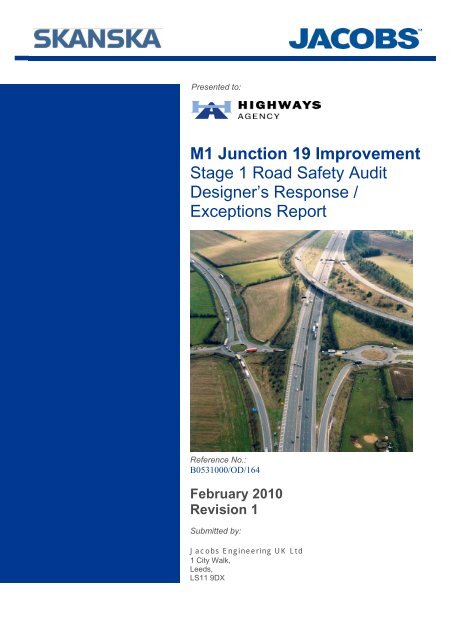
Presented to:<br />
M1 Junction 19 Improvement<br />
<strong>Stage</strong> 1 <strong>Road</strong> <strong>Safety</strong> <strong>Audit</strong><br />
Designer’s <strong>Response</strong> /<br />
Exceptions Report<br />
Reference No.:<br />
B0531000/OD/164<br />
February 2010<br />
Revision 1<br />
Submitted by:<br />
Jacobs Engineering UK Ltd<br />
1 City Walk,<br />
Leeds,<br />
LS11 9DX
M1 Junction 19 Improvement<br />
<strong>Stage</strong> 1 <strong>Road</strong> <strong>Safety</strong> <strong>Audit</strong> Designer’s<br />
<strong>Response</strong> / Exceptions Report<br />
……………………………………………………………………. Jacobs Project Manager<br />
Issue History:<br />
Date Revision Status Comments<br />
July 2009 0 Draft<br />
February 2010 1 Final<br />
This document has been prepared by a division, subsidiary or affiliate of Jacobs Engineering U.K. Limited (“Jacobs”) in its professional<br />
capacity as consultants in accordance with the terms and conditions of Jacobs’ contract with the commissioning party (the “Client”).<br />
Regard should be had to those terms and conditions when considering and/or placing any reliance on this document. No part of this<br />
document may be copied or reproduced by any means without prior written permission from Jacobs. If you have received this<br />
document in error, please destroy all copies in your possession or control and notify Jacobs.<br />
Any advice, opinions, or recommendations within this document (a) should be read and relied upon only in the context of the<br />
document as a whole; (b) do not, in any way, purport to include any manner of legal advice or opinion; (c) are based upon the<br />
information made available to Jacobs at the date of this document and on current UK standards, codes, technology and construction<br />
practices as at the date of this document. It should be noted and it is expressly stated that no independent verification of any of the<br />
documents or information supplied to Jacobs has been made. No liability is accepted by Jacobs for any use of this document, other<br />
than for the purposes for which it was originally prepared and provided. Following final delivery of this document to the Client, Jacobs<br />
will have no further obligations or duty to advise the Client on any matters, including development affecting the information or advice<br />
provided in this document.<br />
This document has been prepared for the exclusive use of the Client and unless otherwise agreed in writing by Jacobs, no other party<br />
may use, make use of or rely on the contents of this document. Should the Client wish to release this document to a third party,<br />
Jacobs may, at its discretion, agree to such release provided that (a) Jacobs’ written agreement is obtained prior to such release; and<br />
(b) by release of the document to the third party, that third party does not acquire any rights, contractual or otherwise, whatsoever<br />
against Jacobs and Jacobs, accordingly, assume no duties, liabilities or obligations to that third party; and (c) Jacobs accepts no<br />
responsibility for any loss or damage incurred by the Client or for any conflict of Jacobs’ interests arising out of the Client's release of<br />
this document to the third party.<br />
B0531000/OD/164 February 2010
M1 Junction 19 Improvement<br />
<strong>Stage</strong> 1 <strong>Road</strong> <strong>Safety</strong> <strong>Audit</strong> Designer’s <strong>Response</strong> /<br />
Exceptions Report<br />
CONTENTS<br />
1 INTRODUCTION 1<br />
2 ITEMS RAISED FROM THIS ROAD SAFETY AUDIT 3<br />
2.1 General.........................................................................................................................3<br />
2.2 Junctions ......................................................................................................................8<br />
2.3 Non Motorised User Provision....................................................................................10<br />
2.4 <strong>Road</strong> Signs, Carriageway Marking and Lighting ........................................................11<br />
3 CONCLUSION 17<br />
Rev.:1<br />
i Issued: February 2010
M1 Junction 19 Improvement<br />
<strong>Stage</strong> 1 <strong>Road</strong> <strong>Safety</strong> <strong>Audit</strong> Designer’s <strong>Response</strong> /<br />
Exceptions Report<br />
PAGE NOT USED<br />
Rev.:1<br />
ii Issued: February 2010
M1 Junction 19 Improvement<br />
<strong>Stage</strong> 1 <strong>Road</strong> <strong>Safety</strong> <strong>Audit</strong> Designer’s <strong>Response</strong> /<br />
Exceptions Report<br />
1 INTRODUCTION<br />
1.1.1 This report is the Designer’s <strong>Response</strong> and Exceptions Report resulting from the<br />
<strong>Stage</strong> 1 <strong>Road</strong> <strong>Safety</strong> <strong>Audit</strong> for the M1 Junction 19 Improvement Scheme carried out<br />
by Jacobs on the Preferred Route.<br />
1.1.2 The findings of the <strong>Road</strong> <strong>Safety</strong> <strong>Audit</strong> are detailed within the report entitled “M1<br />
Junction 19 Improvement <strong>Road</strong> <strong>Safety</strong> <strong>Audit</strong> <strong>Stage</strong> 1 June 2009, Original”.<br />
1.1.3 The <strong>Stage</strong> 1 <strong>Road</strong> <strong>Safety</strong> <strong>Audit</strong> review was carried out by:<br />
• John Barrell, BSC, CEng, MICE, FIHT, MSoRSA, MIRSO<br />
• Colin Wright, MSc, MEng, AMIHT<br />
• Vincent Holden, BA, MIHT, MILT<br />
• Laura Tweddle, MEng, GMICE, MIHT<br />
1.1.4 For details of the drawings and documents examined as part of the <strong>Audit</strong>, refer to the<br />
<strong>Stage</strong> 1 <strong>Audit</strong> Report - Paragraph 1.8.<br />
1.1.5 The findings and recommendations of the <strong>Stage</strong> 1 <strong>Road</strong> <strong>Safety</strong> <strong>Audit</strong> are summarised<br />
together with the Designer’s responses, which reflect the scheme design at July<br />
2009.<br />
1.1.6 Section 3 of this report concludes the Designer’s findings.<br />
Rev.:1<br />
1 Issued: February 2010
M1 Junction 19 Improvement<br />
<strong>Stage</strong> 1 <strong>Road</strong> <strong>Safety</strong> <strong>Audit</strong> Designer’s <strong>Response</strong> /<br />
Exceptions Report<br />
PAGE NOT USED<br />
Rev.:1<br />
2 Issued: February 2010
M1 Junction 19 Improvement<br />
<strong>Stage</strong> 1 <strong>Road</strong> <strong>Safety</strong> <strong>Audit</strong> Designer’s <strong>Response</strong> /<br />
Exceptions Report<br />
2 ITEMS RAISED FROM THIS ROAD SAFETY AUDIT<br />
2.1 GENERAL<br />
Problem 1 - Rationale of emergency / maintenance access routes<br />
At M1 / M6 / A14 interchange<br />
Problem<br />
There are four emergency / maintenance<br />
access routes proposed from the local<br />
road network to the M1, M6 and A14.<br />
These include access points between<br />
structures S/7 and S/8 and on the M1 –<br />
A14 Eastbound Link at the end of a<br />
downhill section. The access points should<br />
be located where there is adequate<br />
visibility for vehicles using them to access<br />
and egress safely. In addition the routes<br />
should be signed and gated so they are<br />
not used as short cuts for local vehicles to<br />
access the trunk road network. This is<br />
made more likely by removal of access<br />
from local roads to the trunk roads in this<br />
new design.<br />
Recommendation<br />
Review provision of emergency /<br />
maintenance access routes to ensure they<br />
all are necessary, provide adequate<br />
visibility and are not used by local vehicles<br />
as a short cut to access M1, M6 and A14.<br />
Designer’s <strong>Response</strong><br />
All of the access points to/from the emergency/maintenance routes are to be gated (on<br />
the local road side) and locked to prevent inappropriate use by local traffic (vehicles,<br />
pedestrians, animals, etc). The provision of CCTV to cover all access points is currently<br />
under consideration as part of the Motorway Communications design.<br />
The preliminary design of the junctions between the emergency / maintenance access<br />
and the local road network are designed to be perceived as field accesses and thus<br />
inconspicuous and in keeping with the rural environment.<br />
For all accesses a minimum of 120m stopping sight distance (one step below the<br />
desirable minimum of 160m for an 85kph design speed) would be provided on the Major<br />
<strong>Road</strong>.<br />
For the three accesses on the south side of the Local Link <strong>Road</strong>, standard visibility of<br />
160m for the Major <strong>Road</strong> design speed of 85kph would be provided from a point a<br />
minimum of 2m back from the give way line in accordance with TD 41/95, Para. 2.21 for<br />
a lightly used access with particularly difficult site conditions.<br />
For the access on the north side of the Local Link <strong>Road</strong> and the access to the west of<br />
Swinford <strong>Road</strong> visibility of 90m (2 step reduction) would be provided from a point a<br />
minimum of 2m back from the give way line, with visibility along the Major <strong>Road</strong> of 120m<br />
(1 step reduction) being provided in the vicinity of the access.<br />
Due to the low anticipated usage (only one vehicle is expected to join/leave the Major<br />
<strong>Road</strong> at one time) and the requirements TD41/95 being specific to access to / from high<br />
standard Trunk <strong>Road</strong>s, the proposals discussed above are considered acceptable.<br />
Rev.:1<br />
3 Issued: February 2010
M1 Junction 19 Improvement<br />
<strong>Stage</strong> 1 <strong>Road</strong> <strong>Safety</strong> <strong>Audit</strong> Designer’s <strong>Response</strong> /<br />
Exceptions Report<br />
Exception<br />
No exception is sought at this stage; although an exception may be sought at the next<br />
stage of design development for reduced visibility should the issue be raised in<br />
subsequent <strong>Road</strong> <strong>Safety</strong> <strong>Audit</strong>s.<br />
Problem 2 - Additional vehicles using this route<br />
A426 between M1 J20 and M6 J1<br />
Problem<br />
The proposed junction layout removes the<br />
ability for vehicles to travel from M1<br />
Southbound to M6 Westbound and from<br />
M6 Eastbound to M1 Northbound. Any<br />
vehicles that previously made either of<br />
these movements will now have to use the<br />
A426. The auditor is unsure whether the<br />
capacity of this route and junctions will be<br />
suitable for the additional vehicles.<br />
Recommendation<br />
Provide assessment of impact of scheme<br />
on A426.<br />
Designer’s <strong>Response</strong><br />
The Preferred Route has been developed based on traffic forecasting. This identified<br />
that existing demand and forecast flows for the M6 westbound to M1 northbound and M1<br />
southbound to M6 westbound movements are currently and forecast to be very low. The<br />
alternative route for these movements using the strategic road network is the M69 and<br />
the A426.<br />
A comparison of the forecast traffic flows on the A426 in the do-minimum scenario (no<br />
junction improvement) and the do-something scenario (following improvement to the<br />
junction) in both the opening year (2014) and the design year (2029) indicate a small<br />
reduction in traffic along the A426. This is considered to be due to traffic currently<br />
bypassing M1 Junction 19, transferring to the motorway network following removal of the<br />
congestion and delay currently encountered at M1 Junction 19.<br />
Exception<br />
No exception required.<br />
Rev.:1<br />
4 Issued: February 2010
M1 Junction 19 Improvement<br />
<strong>Stage</strong> 1 <strong>Road</strong> <strong>Safety</strong> <strong>Audit</strong> Designer’s <strong>Response</strong> /<br />
Exceptions Report<br />
Problem 3 - Potential ponding<br />
Approach to junction of Swinford <strong>Road</strong> and Local Link <strong>Road</strong><br />
Problem<br />
The approach to the junction on Swinford<br />
<strong>Road</strong> goes downhill to go underneath M1 –<br />
M6 Northbound, M6 – A14 and M6 – M1<br />
Southbound Links, before going uphill to<br />
the T junction. The lowest point is under<br />
S/9 M6 – A1 Link and thus there is<br />
potential for ponding to occur at this<br />
location. Flooding in this location could<br />
lead to loss of control of vehicles and<br />
potential damage to structures if vehicles<br />
leave the carriageway.<br />
Recommendation<br />
Ensure adequate drainage facilities are<br />
provided on Swinford <strong>Road</strong>.<br />
Designer’s <strong>Response</strong><br />
Initial drainage proposals reported in the “Contractors Proposals for Drainage” propose a<br />
gravity drainage network (no pumping station) for the trapped cutting.<br />
At detailed design, the pipe network and gully spacing will be designed in accordance<br />
with the requirements of HD33/06 which requires the drainage system to accommodate<br />
a larger storm event for trapped cuttings.<br />
Exception<br />
No exception required.<br />
Rev.:1<br />
5 Issued: February 2010
M1 Junction 19 Improvement<br />
<strong>Stage</strong> 1 <strong>Road</strong> <strong>Safety</strong> <strong>Audit</strong> Designer’s <strong>Response</strong> /<br />
Exceptions Report<br />
Problem 4 - Location of emergency maintenance access<br />
M1 – A14 Eastbound Link<br />
Problem<br />
The emergency maintenance access point<br />
is located at the end of a downhill gradient<br />
section of the M1 – A14 Eastbound Link.<br />
Emergency vehicles may encounter<br />
vehicles at high speeds given the downhill<br />
gradient, and whose drivers are not<br />
expecting vehicles to be exiting from this<br />
location.<br />
Recommendation<br />
If this location is to be retained ensure<br />
adequate visibility of emergency access<br />
point for vehicles on M1 – A14 Eastbound<br />
Link.<br />
Designer’s <strong>Response</strong><br />
The emergency maintenance access point has been designed to include diverge and<br />
merge tapers to the back of the 3.3m hardshoulder in order that vehicle can accelerate /<br />
decelerate to an appropriate speed prior to joining / leaving the hardshoulder.<br />
At this stage it is anticipated that all vehicles using the facility would be entering or<br />
exiting the motorway network under flashing lights in order increase awareness.<br />
Vehicles travelling in lane 1 of the M1 – A14 Eastbound Link would have a Stopping<br />
Sight Distance of at least 160m for obstructions within lanes 1 and 2, which is<br />
appropriate for the design speed of 85kph (in accordance with the requirements of<br />
TD22/06 Layout of Grade Separated Junctions).<br />
Consideration will be given the provision of an advisory 50mph or 60mph speed limit and<br />
additional traffic signs at the next stage of design development.<br />
Exception<br />
No exception required.<br />
Rev.:1<br />
6 Issued: February 2010
M1 Junction 19 Improvement<br />
<strong>Stage</strong> 1 <strong>Road</strong> <strong>Safety</strong> <strong>Audit</strong> Designer’s <strong>Response</strong> /<br />
Exceptions Report<br />
Problem 5 - Capacity reduction of M1 – M6 Northbound Link.<br />
M1 – M6 Northbound Link.<br />
Problem<br />
The proposed modifications to the junction<br />
have reduced the number of lanes on the<br />
M1 – M6 Northbound Link from 3 lanes to<br />
2 lanes. Diverge arrangements remain<br />
similar on the M1 with no lane drop. The<br />
auditor is concerned that a reduction in the<br />
number of lanes on the M1 – M6<br />
Northbound Link could lead to capacity<br />
issues.<br />
Recommendation<br />
Provide an assessment of junction<br />
operation to address link capacity issues.<br />
Designer’s <strong>Response</strong><br />
Traffic surveys and traffic forecasting indicates that the existing, opening year and<br />
design year (15 years after opening) traffic flows do / will not require the provision of 3<br />
lanes on this link.<br />
Exception<br />
No exception required.<br />
Rev.:1<br />
7 Issued: February 2010
M1 Junction 19 Improvement<br />
<strong>Stage</strong> 1 <strong>Road</strong> <strong>Safety</strong> <strong>Audit</strong> Designer’s <strong>Response</strong> /<br />
Exceptions Report<br />
2.2 JUNCTIONS<br />
Problem 6 - Forward visibility on Shawell Lane approach<br />
Junction of Shawell Lane and Local Link <strong>Road</strong><br />
Problem<br />
The approach to the junction on Shawell<br />
Lane goes under the mainline M6 and then<br />
turns sharply to the right to provide a T<br />
junction arrangement with the Link <strong>Road</strong>.<br />
Visibility of this bend will be impaired by<br />
the underpass and alignment of the link<br />
road. This could result in vehicles<br />
attempting to go straight on instead of<br />
turning right.<br />
Recommendation<br />
Provide signage before the underpass<br />
giving warning of the approaching right<br />
hand bend and junction. Provide deflection<br />
and landscaping at the bend so that<br />
forward visibility of the link road alignment<br />
is reduced and vehicles naturally turn right.<br />
Designer’s <strong>Response</strong><br />
At the detailed design stage, the traffic signs and road markings design will be<br />
developed to include appropriate signage prior to the underpass to give warning of<br />
approaching right hand bend and junction. Deflection at the bend will also be provided<br />
through either landscape mounding and planting or appropriate traffic signs.<br />
Exception<br />
No exception required.<br />
Rev.:1<br />
8 Issued: February 2010
M1 Junction 19 Improvement<br />
<strong>Stage</strong> 1 <strong>Road</strong> <strong>Safety</strong> <strong>Audit</strong> Designer’s <strong>Response</strong> /<br />
Exceptions Report<br />
Problem 7 - Visibility of westbound vehicles on Local Link <strong>Road</strong><br />
Junction of Local Link <strong>Road</strong> and Swinford <strong>Road</strong><br />
Problem<br />
Vehicles travelling west on the Local Link<br />
<strong>Road</strong> on the approach to Swinford <strong>Road</strong><br />
travel on an uphill gradient under<br />
structures S/8, S/7 and S/2 before the road<br />
goes downhill (chainage 1950) to the<br />
junction (chainage 1750). Vehicles exiting<br />
Swinford <strong>Road</strong> with have their visibility to<br />
the right reduced by this crest and the<br />
tunnel effect that the three structures in<br />
close proximity provides.<br />
Recommendation<br />
Consider levelling out the vertical profile on<br />
the Local Link <strong>Road</strong> to improve visibility at<br />
the Swinford <strong>Road</strong> junction.<br />
Designer’s <strong>Response</strong><br />
Stopping sight visibility of at least 160m has been provided to / from the junction based<br />
on a design speed of 85kph which is considered appropriate for a rural road and in<br />
keeping with the surround rural lanes.<br />
It should be noted that the Local Link <strong>Road</strong> has been designed as a non-overtaking<br />
section of road to the east of its junction with Swinford <strong>Road</strong>. Increasing visibility would<br />
encourage vehicles to travel at higher speeds and may result in inappropriate overtaking<br />
manoeuvres.<br />
Exception<br />
The Designer requests an exception as increasing visibility at this junction would<br />
encourage vehicle to travel at higher speeds.<br />
Rev.:1<br />
9 Issued: February 2010
M1 Junction 19 Improvement<br />
<strong>Stage</strong> 1 <strong>Road</strong> <strong>Safety</strong> <strong>Audit</strong> Designer’s <strong>Response</strong> /<br />
Exceptions Report<br />
2.3 NON MOTORISED USER PROVISION<br />
Problem 8 - Provision for non motorised users<br />
Local road network from Swinford <strong>Road</strong> to Local Link <strong>Road</strong> to Rugby <strong>Road</strong><br />
Problem<br />
The provision for non motorised users has<br />
not been made clear to the auditors. There<br />
is existing provision from Swinford <strong>Road</strong> to<br />
Rugby <strong>Road</strong>. The new layout must make<br />
provision for non motorised users and<br />
should be easily understood by them.<br />
Recommendation<br />
Provide details of non motorised user<br />
provision to the audit team.<br />
Designer’s <strong>Response</strong><br />
The following facilities for non motorised users are proposed within the limits of the local<br />
road network:<br />
Cyclists<br />
Provision for cyclists as agreed with the Cyclist Touring Club during recent consultations:<br />
1) Cyclists to use the carriageways of the proposed local roads<br />
Equestrians<br />
Provision for horse riders agreed with the British Horse Society at recent consultations:<br />
1) Minimum facilities to be provided within the limits of the local road construction<br />
works - horses to use grassed verge with a minimum width of 2.0m if no footway<br />
to be provided or 4.0m verge including a 1.5m footway at the back of the verge<br />
Pedestrians<br />
Provision for pedestrians agreed with the Ramblers Association and local Parish<br />
Councils at recent consultations:<br />
1) Utility link between Swinford and Catthorpe - 1.5m footway from Swinford village<br />
to the limit of the local road improvement works on Swinford <strong>Road</strong>, reducing to<br />
1.2m up to Catthorpe village<br />
2) Recreational link between the utility link and Bridleway X14 – 3.0m grassed<br />
verge to allow combined use by pedestrians and equestrians in the northern<br />
verge of the Local Link <strong>Road</strong><br />
Exception<br />
No exception required.<br />
Rev.:1<br />
10 Issued: February 2010
M1 Junction 19 Improvement<br />
<strong>Stage</strong> 1 <strong>Road</strong> <strong>Safety</strong> <strong>Audit</strong> Designer’s <strong>Response</strong> /<br />
Exceptions Report<br />
2.4 ROAD SIGNS, CARRIAGEWAY MARKING AND LIGHTING<br />
Problem 9 - Change of road layout, provision of signage and link capacity<br />
M6 Eastbound approach to junction with M1 and A14<br />
Problem<br />
The current junction layout is such that<br />
vehicles wishing to use M1 Southbound<br />
use the two right hand lanes. The new<br />
layout is the opposite where vehicles<br />
wishing to use M1 Southbound use the left<br />
hand lanes. The proposed gantry signage<br />
ADS1, ADS2, and ADS3 indicates that to<br />
use M1 Southbound the left hand lane<br />
must be used. This does not match TT1<br />
and TT2 which show that the M1<br />
Southbound can be reached from the<br />
middle lane as well. Given that the current<br />
provision for this movement is that two<br />
dedicated lanes becoming three on the M6<br />
– M1 Southbound Link, the auditor is<br />
concerned that there may be a capacity<br />
issue with the current layout which is one<br />
dedicated lane and a shared lane on the<br />
M6 becoming two on the M6 – M1<br />
Southbound Link.<br />
Recommendation<br />
For this change in layout to work without<br />
excessive late lane changes, the road<br />
markings and signage must be easily<br />
understood. Ensure that signage clearly<br />
indicates that M1 Southbound can be<br />
reached from the middle lane and provide<br />
lane destination markings on the road<br />
surface. An assessment of junction<br />
capacity will also be necessary.<br />
Designer’s <strong>Response</strong><br />
The proposed Type D (Option 1) Ghost Island diverge for Lane Drop with three lanes<br />
upstream of the diverge, two lanes on the connector road and two lanes downstream of<br />
the diverge has been included in the design following a review of the forecast traffic<br />
flows for both the opening year (2014) and the design year (2029) to meet the<br />
requirements of TD22/06 Layout of Grade Separated Junctions.<br />
At the next stage of design development, the traffic signs and road marking design will<br />
be reviewed to ensure that signage clearly indicates that M1 southbound can be reached<br />
from the middle lane and provide lane destination markings on the road surface.<br />
Exception<br />
No exception required.<br />
Rev.:1<br />
11 Issued: February 2010
M1 Junction 19 Improvement<br />
<strong>Stage</strong> 1 <strong>Road</strong> <strong>Safety</strong> <strong>Audit</strong> Designer’s <strong>Response</strong> /<br />
Exceptions Report<br />
Problem 10 - Spacing of signs on gantry<br />
Junction of M6 – A14 and M1 Southbound<br />
Problem<br />
At the nosing of the M1 Southbound<br />
diverge from the M6 – A14, gantry sign<br />
RC1 is provided. The sign faces do not<br />
appear to span the lanes correctly and<br />
could lead to driver confusion and unsafe<br />
lane movements.<br />
Recommendation<br />
Ensure RC1 spans lanes correctly.<br />
Designer’s <strong>Response</strong><br />
At the next stage of design development, the traffic signs and road marking design will<br />
be reviewed to ensure that sign face RC1 correctly spans lanes.<br />
Exception<br />
No exception required.<br />
Problem 11 - Location of sign MIS3A<br />
M1 – M6 Northbound Link<br />
Problem<br />
This sign indicates two additional lanes of<br />
traffic joining from the right. At its location<br />
there is hatching and a merging lane to the<br />
right before the two mainline traffic lanes.<br />
This could cause driver confusion.<br />
Recommendation<br />
Move MIS3A further down the slip road or<br />
replace with another MIS3.<br />
Designer’s <strong>Response</strong><br />
At the next stage of design development, the traffic signs and road marking design will<br />
be reviewed to consider moving traffic sign MIS3A down the slip road or replacing it with<br />
another MIS3 traffic sign.<br />
Exception<br />
No exception required.<br />
Rev.:1<br />
12 Issued: February 2010
M1 Junction 19 Improvement<br />
<strong>Stage</strong> 1 <strong>Road</strong> <strong>Safety</strong> <strong>Audit</strong> Designer’s <strong>Response</strong> /<br />
Exceptions Report<br />
Problem 12 - Speed enforcement on these links<br />
Entry to M6 – M1 Southbound Link, M1 – M6 Northbound Link, M1 – A14<br />
Eastbound Link and A14 – M1 Northbound Link<br />
Problem<br />
These links have a design speed of 85kph<br />
and as such drivers entering onto these<br />
links must be made aware of the reduced<br />
speed limit and enforcement may be<br />
necessary.<br />
Recommendation<br />
Provide speed limit signs on entry to all of<br />
these links and provide details of how the<br />
speed limit will be enforced.<br />
Designer’s <strong>Response</strong><br />
The four interchange links proposed as part of the Preferred Route and presented on the<br />
drawings reviewed by the <strong>Road</strong> <strong>Safety</strong> <strong>Audit</strong> team have been designed in accordance<br />
with the requirements of TD22/06 Layout of Grade Separated Junctions. The design<br />
speed of 85kph is in accordance with the requirements of Table 4/1 of TD22 for an<br />
interchange link between rural mainlines with a design speed of 120kph.<br />
A minimum stopping sight distance (SSD) of 160m is proposed between the back of<br />
diverge layout nose and the back of the merge layout nose. Full mainline SSD of 295m<br />
is proposed over the full length of the merge and diverge layouts in accordance with the<br />
requirements of TD 9 (Highway Link Design) and TD 22.<br />
However, should the issue continue to be raised in subsequent <strong>Road</strong> <strong>Safety</strong> <strong>Audit</strong>s<br />
consideration could be given to the provision of an advisory 50mph or 60mph speed limit<br />
and additional traffic signs.<br />
Exception<br />
The Designer requests an exception as provision of speed limits on these four<br />
interchange links is not considered necessary and would not be in keeping with current<br />
practise at other similar locations on the motorway and trunk road network.<br />
Rev.:1<br />
13 Issued: February 2010
M1 Junction 19 Improvement<br />
<strong>Stage</strong> 1 <strong>Road</strong> <strong>Safety</strong> <strong>Audit</strong> Designer’s <strong>Response</strong> /<br />
Exceptions Report<br />
Problem 13 - Sign face MIS6<br />
A14 – M1 Northbound Link.<br />
Problem<br />
MIS6 is shown in two locations on the A14<br />
– M1 Northbound Link. However the sign<br />
face detail for this sign is not included in<br />
Drawing No. W/B0531000/B/1200/013.<br />
Recommendation<br />
Provide details of sign face MIS6.<br />
Designer’s <strong>Response</strong><br />
At the next stage of design development, the traffic signs and road marking design will<br />
be amended to remove sign face MIS6 as no sign is required at these locations.<br />
Exception<br />
No exception required.<br />
Problem 14 - Location of sign DS2<br />
Junction of A14 – M6 and M1 Northbound<br />
Problem<br />
At the nosing of the M1 Northbound<br />
diverge from the A14 – M6 sign DS2<br />
indicates the route to M1 Northbound. The<br />
location of this sign could obscure the view<br />
of the offside MS1A motorway regulations<br />
in force sign.<br />
Recommendation<br />
Ensure DS2 does not obscure MS1A.<br />
Designer’s <strong>Response</strong><br />
At the next stage of design development, the traffic signs and road marking design will<br />
be amended to ensure that traffic sign DS2 does not obscure traffic sign MS1A.<br />
Exception<br />
No exception required.<br />
Rev.:1<br />
14 Issued: February 2010
M1 Junction 19 Improvement<br />
<strong>Stage</strong> 1 <strong>Road</strong> <strong>Safety</strong> <strong>Audit</strong> Designer’s <strong>Response</strong> /<br />
Exceptions Report<br />
Problem 15 - Signage for non motorway traffic<br />
Junction of A14 and A5199<br />
Problem<br />
The new junction layout removes any<br />
access to the local road network from the<br />
A14. Therefore under this layout non<br />
motorway traffic must leave the A14 at the<br />
junction with the A5199 approximately 6<br />
miles east.<br />
Recommendation<br />
Provide details of signage for non<br />
motorway traffic using the A14.<br />
Designer’s <strong>Response</strong><br />
At the next stage of design development, the traffic signs and road marking design will<br />
be amended to include details of signage for non motorway traffic using the A14 to exit<br />
at its junction with the A5199.<br />
Exception<br />
No exception required.<br />
Problem 16 - Sign face MIS5<br />
M1 – A14 Eastbound Link<br />
Problem<br />
MIS5 is repeated at two locations on the<br />
M1 – A14 Eastbound Link. This sign shows<br />
a lane reduction from 4 lanes to 3 to<br />
indicate the slip lane merging into the<br />
mainline traffic. This sign should show 3<br />
lanes becoming 2 and should also be on a<br />
green background rather than blue to<br />
reflect the end of motorway.<br />
Recommendation<br />
Amend sign MIS5.<br />
Designer’s <strong>Response</strong><br />
At the next stage of design development, the traffic signs and road marking design will<br />
be amended to introduce additional traffic signs MIS6 to show 3 lanes becoming 2 using<br />
a green background.<br />
Exception<br />
No exception required.<br />
Rev.:1<br />
15 Issued: February 2010
M1 Junction 19 Improvement<br />
<strong>Stage</strong> 1 <strong>Road</strong> <strong>Safety</strong> <strong>Audit</strong> Designer’s <strong>Response</strong> /<br />
Exceptions Report<br />
PAGE NOT USED<br />
Rev.:1<br />
16 Issued: February 2010
M1 Junction 19 Improvement<br />
<strong>Stage</strong> 1 <strong>Road</strong> <strong>Safety</strong> <strong>Audit</strong> Designer’s <strong>Response</strong> /<br />
Exceptions Report<br />
3 CONCLUSION<br />
3.1.1 The Designer has reviewed the issues raised by the <strong>Audit</strong> Team during this <strong>Stage</strong> 1<br />
<strong>Road</strong> <strong>Safety</strong> <strong>Audit</strong>.<br />
3.1.2 The Designer has considered all of the <strong>Audit</strong>or’s recommendation and has provided<br />
his response in Section 2 of this report.<br />
3.1.3 Two exceptions are sought as this stage for Problems 7 and 12, the justification for<br />
which is summarised below:<br />
• The Designer considers amending the design to increase visibility at the junction<br />
of the Local Link <strong>Road</strong> and Swinford <strong>Road</strong> would encourage vehicles to travel at<br />
higher speeds and could result in inappropriate overtaking in the vicinity of the<br />
junction<br />
• The Designer considers the introduction of a mandatory speed limit on the four<br />
interchange links is inappropriate. The design has been developed in<br />
accordance with the requirements of current design standards and would not be<br />
in keeping with current practise at other similar locations on the motorway and<br />
trunk road network<br />
3.1.4 Many of the problems raised will require amendments to the design prior to a <strong>Stage</strong> 2<br />
<strong>Road</strong> <strong>Safety</strong> <strong>Audit</strong> which may not resolve all the concerns of the <strong>Audit</strong> Team. It is<br />
considered prudent for the Highways Agency to discuss the following issue with the<br />
<strong>Audit</strong> Team prior to publication of Draft Orders:<br />
• The introduction of an advisory speed limit of 50 or 60mph on the four<br />
interchange links, denoted by traffic signs to TSRGD 2002 (Traffic Signs and<br />
General Directions) diagram 513 (Maximum speed in miles per hour advised at a<br />
bend or other hazard) in combination with traffic signs to diagram 512 (Bend<br />
ahead).<br />
Rev.:1<br />
17 Issued: February 2010