WGS84RPT.tif:Corel PHOTO-PAINT - Henry A. Rowland Department ...
WGS84RPT.tif:Corel PHOTO-PAINT - Henry A. Rowland Department ...
WGS84RPT.tif:Corel PHOTO-PAINT - Henry A. Rowland Department ...

You also want an ePaper? Increase the reach of your titles
YUMPU automatically turns print PDFs into web optimized ePapers that Google loves.
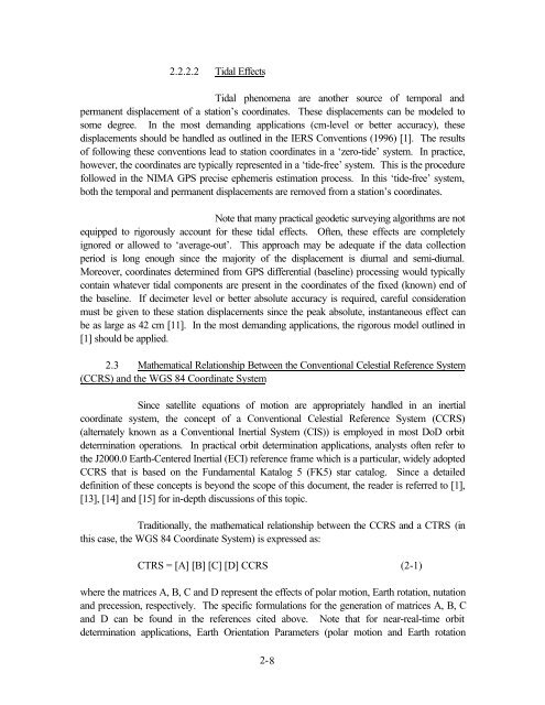
2.2.2.2 Tidal Effects<br />
Tidal phenomena are another source of temporal and<br />
permanent displacement of a station’s coordinates. These displacements can be modeled to<br />
some degree. In the most demanding applications (cm-level or better accuracy), these<br />
displacements should be handled as outlined in the IERS Conventions (1996) [1]. The results<br />
of following these conventions lead to station coordinates in a ‘zero-tide’ system. In practice,<br />
however, the coordinates are typically represented in a ‘tide-free’ system. This is the procedure<br />
followed in the NIMA GPS precise ephemeris estimation process. In this ‘tide-free’ system,<br />
both the temporal and permanent displacements are removed from a station’s coordinates.<br />
Note that many practical geodetic surveying algorithms are not<br />
equipped to rigorously account for these tidal effects. Often, these effects are completely<br />
ignored or allowed to ‘average-out’. This approach may be adequate if the data collection<br />
period is long enough since the majority of the displacement is diurnal and semi-diurnal.<br />
Moreover, coordinates determined from GPS differential (baseline) processing would typically<br />
contain whatever tidal components are present in the coordinates of the fixed (known) end of<br />
the baseline. If decimeter level or better absolute accuracy is required, careful consideration<br />
must be given to these station displacements since the peak absolute, instantaneous effect can<br />
be as large as 42 cm [11]. In the most demanding applications, the rigorous model outlined in<br />
[1] should be applied.<br />
2.3 Mathematical Relationship Between the Conventional Celestial Reference System<br />
(CCRS) and the WGS 84 Coordinate System<br />
Since satellite equations of motion are appropriately handled in an inertial<br />
coordinate system, the concept of a Conventional Celestial Reference System (CCRS)<br />
(alternately known as a Conventional Inertial System (CIS)) is employed in most DoD orbit<br />
determination operations. In practical orbit determination applications, analysts often refer to<br />
the J2000.0 Earth-Centered Inertial (ECI) reference frame which is a particular, widely adopted<br />
CCRS that is based on the Fundamental Katalog 5 (FK5) star catalog. Since a detailed<br />
definition of these concepts is beyond the scope of this document, the reader is referred to [1],<br />
[13], [14] and [15] for in-depth discussions of this topic.<br />
Traditionally, the mathematical relationship between the CCRS and a CTRS (in<br />
this case, the WGS 84 Coordinate System) is expressed as:<br />
CTRS = [A] [B] [C] [D] CCRS (2-1)<br />
where the matrices A, B, C and D represent the effects of polar motion, Earth rotation, nutation<br />
and precession, respectively. The specific formulations for the generation of matrices A, B, C<br />
and D can be found in the references cited above. Note that for near-real-time orbit<br />
determination applications, Earth Orientation Parameters (polar motion and Earth rotation<br />
2-8