Session S6: Schottky Diodes and Mixers - Department of Physics
Session S6: Schottky Diodes and Mixers - Department of Physics
Session S6: Schottky Diodes and Mixers - Department of Physics

You also want an ePaper? Increase the reach of your titles
YUMPU automatically turns print PDFs into web optimized ePapers that Google loves.
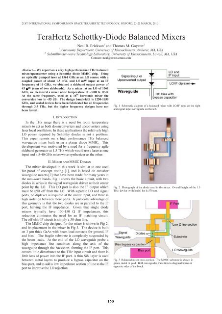
21ST INTERNATIONAL SYMPOSIUM ON SPACE TERAHERTZ TECHNOLOGY, OXFORD, 23-25 MARCH, 2010<br />
TeraHertz <strong>Schottky</strong>-Diode Balanced <strong>Mixers</strong><br />
Neal R. Erickson 1 <strong>and</strong> Thomas M. Goyette 2<br />
1 .Astronomy <strong>Department</strong>, University <strong>of</strong> Massachusetts, Amherst, MA, USA<br />
2. Submillimeter-wave Technology Laboratory, University <strong>of</strong> Massachusetts, Lowell, MA, USA<br />
Contact: neal@astro.umass.edu<br />
Abstract— We report on a very high performance THz balanced<br />
mixer/upconverter using a <strong>Schottky</strong> diode MMIC chip. Using<br />
an optically pumped laser at 1561 GHz as an LO source with a<br />
coupled power <strong>of</strong> about 1.5 mW, <strong>and</strong> 1.5 mW input at an IF<br />
frequency <strong>of</strong> 10 GHz, we obtained a sideb<strong>and</strong> output power <strong>of</strong><br />
45 W (sum <strong>of</strong> two sideb<strong>and</strong>s). As a mixer, at an LO <strong>of</strong> 1561<br />
GHz, we measured a mixer noise temperature <strong>of</strong> ~3000 K DSB.<br />
At the same frequency, used as a 16 th harmonic mixer the<br />
conversion loss is ~55 dB. The design b<strong>and</strong>width is 1250-1650<br />
GHz, <strong>and</strong> scaled devices have been fabricated for all frequencies<br />
through 3.5 THz, but the higher frequency designs have not<br />
been tested.<br />
Fig. 1 Schematic diagram <strong>of</strong> a balanced mixer with LO/IF input on the right<br />
<strong>and</strong> signal input waveguide on the left.<br />
I. INTRODUCTION<br />
In the THz range there is a need for room temperature<br />
mixers to act as both downconverters <strong>and</strong> upconverters using<br />
laser local oscillators. In these applications the relatively high<br />
LO power required by <strong>Schottky</strong> diodes is not a problem.<br />
This paper reports on a high performance THz balanced<br />
waveguide mixer built using a planar diode MMIC. This<br />
development was motivated by a need for a frequency agile<br />
sideb<strong>and</strong> generator at 1.5 THz which would use a laser as one<br />
input <strong>and</strong> a 5-40 GHz microwave synthesizer as the other.<br />
II. MIXER AND MMIC DESIGN<br />
The mixer developed in this work is similar to one used<br />
for pro<strong>of</strong> <strong>of</strong> concept testing [1], <strong>and</strong> is based on crossbar<br />
waveguide mixers [2] that have been made for many years in<br />
the mm-wave b<strong>and</strong>s. Fig 1 shows the basic circuit, with two<br />
diodes in series in the signal waveguide driven at their center<br />
point by the LO. This LO port is also the IF output which<br />
must be split <strong>of</strong>f from the LO. With separate LO <strong>and</strong> signal<br />
ports, no diplexer is required at the mixer input, <strong>and</strong> there is<br />
high isolation between these ports. A particular advantage <strong>of</strong><br />
this geometry is that the two diodes are in parallel to the IF<br />
port, halving the IF impedance. Given that single diode<br />
mixers typically have 100-150 IF impedances, this<br />
reduction eliminates the need for an IF matching circuit.<br />
The <strong>of</strong>f-chip IF circuit is simply a 50 ohm line.<br />
The MMIC chip designed for the mixer is shown in Fig 2,<br />
<strong>and</strong> its placement in the mixer in Fig 3. The device is built<br />
on 3 µm thick GaAs with beam lead contacts for ground, IF<br />
<strong>and</strong> bias. The fragile substrate is completely suspended by<br />
the beam leads. At the end <strong>of</strong> the LO waveguide probe a<br />
high impedance line continues along the axis <strong>of</strong> the<br />
waveguide through the backshort, forming the IF port. This<br />
creates little disturbance to the THz input circuit <strong>and</strong> there is<br />
little loss <strong>of</strong> power into the IF port. A thin SiN layer is used<br />
between metal layers to produce a bypass capacitor on the<br />
bias port, <strong>and</strong> to add a low impedance section <strong>of</strong> line to the IF<br />
port to improve the LO rejection.<br />
Fig. 2 Photograph <strong>of</strong> the diode used in the mixer. Overall height <strong>of</strong> the 1.5<br />
THz device (with leads) for is 570 um.<br />
Fig. 3 Balanced mixer cross section. The MMIC substrate is shown in<br />
green, metal in gold. Both waveguides transition to diagonal horns on<br />
opposite sides <strong>of</strong> the block.<br />
150