
You also want an ePaper? Increase the reach of your titles
YUMPU automatically turns print PDFs into web optimized ePapers that Google loves.
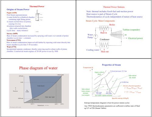
Thermal Power<br />
Origins <strong>of</strong> Steam Power<br />
Papin (1690)<br />
First Steam-operated piston<br />
i) <strong>water</strong> boiled in cylindrical chamber<br />
containing tight fitting piston<br />
ii) steam exerted force on piston,<br />
causing it to rise<br />
iii) piston retracted into chamber<br />
after walls cooled down<br />
(cycle time – many minutes)<br />
Savery (1699)<br />
Rate <strong>of</strong> steam condensation increased by spraying cold <strong>water</strong> over outside <strong>of</strong> piston<br />
chamber (cycle time ~ a minute)<br />
Newcomen (1712)<br />
Rate <strong>of</strong> steam condensation improved still further by injecting cold <strong>water</strong> directly into<br />
steam chamber (cycle time 5-10 seconds)<br />
Watt (1775)<br />
Incorporated separate condenser, thereby removing need to reheat walls <strong>of</strong> piston<br />
chamber. Commercial steam engines <strong>of</strong> 20 kW power in use by 1800<br />
Thermal Power Stations<br />
Note: thermal includes fossil-fuel and nuclear power<br />
Heat source is part <strong>of</strong> Steam Cycle<br />
Thermodynamics <strong>of</strong> cycle independent <strong>of</strong> nature <strong>of</strong> heat source<br />
Steam Cycle: Main Components<br />
Water<br />
Pump<br />
Cooling <strong>water</strong><br />
Heat in<br />
Condenser<br />
Heat out<br />
Boiler<br />
Turbine (expander)<br />
ω<br />
Electrical power<br />
<strong>Phase</strong> <strong>diagram</strong> <strong>of</strong> <strong>water</strong><br />
Temperature K<br />
T<br />
Super-critical<br />
fluid<br />
Properties <strong>of</strong> Steam<br />
Critical pressure 221 bar<br />
Sub-critical<br />
dry steam<br />
p=0.006 bar<br />
Sub-critical<br />
<strong>water</strong>-steam<br />
mixture<br />
(wet steam)<br />
100% <strong>water</strong><br />
0% steam<br />
0% <strong>water</strong><br />
100% steam<br />
Ice-<strong>water</strong> vapour mixture<br />
s<br />
Specific entropy kJ/kg/K<br />
Dryness fraction (quality)<br />
x = m vapour<br />
/(m vapour<br />
+m <strong>water</strong><br />
)<br />
s = (1 − x)s <strong>water</strong><br />
+ xs vapour<br />
Entropy/temperature <strong>diagram</strong> is best for power station cycles<br />
Any TWO thermodynamic parameters are sufficient to define state <strong>of</strong> fluid<br />
eg S,T or P,H (Steam Tables)
Carnot Cycle (Ideal Cycle)<br />
T<br />
Q 12<br />
T 1 2<br />
a<br />
W 41<br />
W 23<br />
Q 34<br />
T b<br />
4 3<br />
S<br />
1) Heat absorption at constant<br />
temperature, T a (boiler) 12<br />
2) Isentropic expansion work<br />
output (turbine) 23<br />
3) Heat rejection at constant<br />
temperature, T b (condenser) 34<br />
4) Isentropic compression<br />
(pump) 41<br />
Energy Conservation (1 st Law <strong>of</strong> Thermodynamics)<br />
Q 12 + W 23 + Q 34 + W 41 = 0<br />
(Note: Q 12<br />
> 0, W 23<br />
< 0, Q 34<br />
< 0, W 41<br />
> 0)<br />
Cycle efficiency, η c = (Useful work out)/(Heat input at T a )<br />
ie η c = (| W 23 | − W 41 )/ Q 12 | = (T a − T b )/ T a = 1 − T b / T a<br />
(Note: T measured in K (absolute temperature) – formal<br />
definition <strong>of</strong> absolute temperature scale)<br />
Practical difficulties in using a Carnot Cycle<br />
1) Boiler operates only in wet-steam regime otherwise temperature<br />
would rise when all the <strong>water</strong> has turned to steam, violating<br />
condition for Carnot Cycle<br />
turbine expands wet steam<br />
<strong>water</strong> droplets hit turbine blades (damage)<br />
2) Maximum temperature (T a ) is limited to ~650 K<br />
efficiency <strong>of</strong> cycle is severely constrained<br />
3) Compression <strong>of</strong> <strong>water</strong>/steam mixture is thermodynamically<br />
unstable (<strong>water</strong> droplets)<br />
very large volume compressor (expensive)<br />
Rankine Cycle overcomes all these problems<br />
T<br />
2b<br />
2a<br />
T b<br />
1b 1a<br />
2c<br />
S<br />
Rankine Cycle<br />
Step 1:<br />
a) Condense all the steam to <strong>water</strong><br />
in the condenser<br />
b) Pumping <strong>water</strong> to high pressure requires<br />
small volume machine and little energy<br />
T<br />
T b<br />
T a<br />
S<br />
Step 3:<br />
Expand dry steam through a turbine<br />
to generate shaft power<br />
In practice, <strong>water</strong> droplets still form in<br />
the low pressure end <strong>of</strong> the turbine, so<br />
the steam is reheated at various stages<br />
Step 2:<br />
Use 3-stage boiler (~ constant pressure)<br />
a) Economiser – <strong>water</strong> heated at constant pressure<br />
b) Evaporator – <strong>water</strong>/steam mixture heated at constant pressure<br />
c) Superheater – dry steam heated at constant pressure<br />
[Note that there is a small drop in pressure through the boiler tube<br />
in order to overcome frictional losses]<br />
T<br />
T a<br />
T b<br />
S<br />
HP<br />
from<br />
IP LP<br />
boiler<br />
reheaters<br />
HP: high pressure turbine<br />
IP: intermediate pressure turbine<br />
LP: low pressure turbine<br />
to condenser
Frictional losses across turbine blades vary like u 2 (F D =½C D ρAu 2 )<br />
ie very large for large u (near speed <strong>of</strong> sound)<br />
Losses reduced significantly by using many stages in series (~50 stages)<br />
Other practical effects limiting efficiency<br />
The loss <strong>of</strong> kinetic energy at each stage is<br />
small and turbulence is reduced<br />
a) Boiler tubes have finite thickness, so outer wall temperature is higher<br />
than <strong>water</strong>/steam temperature<br />
b) Metallurgical limit to temperature/pressure difference boiler tubes<br />
can withstand (creep/crack formation)<br />
c) Many pipes/tubes in flow circuit frictional losses<br />
d) Condenser is a vacuum chamber air leaks in but can not condense,<br />
so ‘air blanket’ forms, preventing <strong>water</strong> vapour from condensing on<br />
cold surface <strong>of</strong> condenser tubes<br />
T<br />
W 12<br />
2<br />
1<br />
3<br />
Q 23<br />
W 34<br />
Q 41<br />
4<br />
Efficiency <strong>of</strong> Rankine Cycle<br />
S<br />
Condenser at 30 C at a pressure <strong>of</strong> 0.04 bar<br />
Compressor increases pressure to 170 bar<br />
Three-stage boiler at 170 bar<br />
a) economiser raises temperature to 352 C<br />
b) evaporator at 352 C<br />
c) superheater raises temperature to 600 C<br />
Adiabatic turbine<br />
T p h f h g s f s g<br />
Water/Steam 30 0.04 126 2566 0.436 8.452<br />
Water/Steam 352 170 1690 2548 3.808 5.181<br />
Dry Steam 600 170 3564 6.603<br />
where h f and h g are the specific enthalpies and s f and s g are the<br />
specific entropies <strong>of</strong> the fluid and gas, respectively, in kJ/kg.<br />
Adiabatic compression or expansion<br />
W = W s + (p 1 v 1 − p 2 v 2 ) = ∆U = u 2 − u 1<br />
W s = (u 2 − u 1 ) − (p 1 v 1 − p 2 v 2 )<br />
= (u 2 + p 2 v 2 ) − (u 1 + p 1 v 1 )<br />
= h 2 − h 1<br />
Work done by the shaft W s<br />
on the fluid<br />
Adiabatic so Q = 0<br />
Total work W<br />
First Law: ∆U = Q + W<br />
Note sign convention<br />
In adiabatic process work done equals change in enthalpy<br />
Specific enthalpy h = u +pv; dh = TdS + Vdp<br />
isobaric, constant pressure, dh = du + pdv = dQ<br />
isentropic dh = dW = Vdp<br />
i) W 12 = V(p 2 − p 1 ) = 10 −3 (170 − 0.04) 10 5<br />
=17 kJ/kg 3<br />
ii) 12 isentropic so<br />
h 2 = h 1 + W 12 = 126 + 17 = 143 kJ/kg<br />
iii) 23 isobaric so<br />
Q 23 = h 3 – h 2 = 3564 − 143 = 3421 kJ/kg<br />
iv) 34 isentropic so<br />
W 34 = h 3 – h 4 and s 3 = s 4<br />
s 4 = (1−x)s f4 + xs g4<br />
s 3 = 6.603 = (1−x)0.436 + 8.452 x<br />
x = 0.769<br />
T<br />
W 12<br />
2<br />
1<br />
Q 23<br />
W 34<br />
Q 41<br />
4<br />
S
Combined Cycle Gas Turbine (CCGT) Stations<br />
v) h 4 = (1−x)h f4 + xh g4<br />
h 4 = (1−x)126 + 2566 x<br />
x = 0.769<br />
h 4 = 2002 kJ/kg<br />
In recent years gas turbines and steam turbines have been combined to<br />
increase the efficiency to around 50-60% (upper temperature ~1200 C)<br />
Gas Turbine<br />
air<br />
34 isentropic so<br />
W 34 = h 3 – h 4<br />
= 3564 – 2002 = 1562 kJ/kg<br />
vi) η = useful work/heat in<br />
= (W 34 – W 12 )/Q 23 = (1562 – 17)/3421<br />
= 0.452 = 45.2%<br />
vii) cf Carnot Cycle<br />
η c = (T 3 − T 4 )/T 3 = (873 − 303)/873<br />
= 0.653 = 65.3%<br />
T<br />
W 12<br />
Q<br />
3<br />
23<br />
2<br />
W 34<br />
1<br />
4<br />
Q 41 S<br />
T<br />
T max<br />
Compressor<br />
Combustion<br />
Compressor<br />
Gaseous<br />
fuel<br />
p<br />
compressed<br />
air<br />
Combustion<br />
Chamber<br />
p atmos<br />
Turbine<br />
Brayton Cycle<br />
S<br />
Turbine<br />
Exhaust gas<br />
a) Heat generated by internal combustion rather than<br />
via a high temperature heat exchanger (boiler)<br />
b) No cooler required since exhaust gases vented to<br />
atmosphere<br />
Plant much smaller. Work done by compressor is<br />
significant, though this is compensated by very high<br />
temperature ~ 1200 C (Turbine blades ceramic coated<br />
and <strong>water</strong> cooled)<br />
ω<br />
CCGT Station<br />
660 MW Power Plant<br />
air<br />
Compressor<br />
Gaseous<br />
fuel<br />
compressed<br />
air<br />
Combustion<br />
Chamber<br />
Turbine<br />
Exhaust gas<br />
Water<br />
Pump<br />
Heat in<br />
Boiler<br />
Turbine<br />
Exhaust gas<br />
Condenser<br />
ω<br />
combustion<br />
Cooling <strong>water</strong><br />
Heat out<br />
T<br />
Rankine<br />
Cycle<br />
compressor<br />
S<br />
turbine<br />
boiler<br />
Brayton<br />
Cycle<br />
Heat <strong>of</strong> exhaust gases used to<br />
raise steam for steam turbine<br />
Many CCGTs have been built in the<br />
UK in the 90s due to availability <strong>of</strong><br />
cheap gas and relaxation <strong>of</strong><br />
governmental controls<br />
Stator for a 660 MW<br />
generator being assembled<br />
Low pressure turbine, part <strong>of</strong> a<br />
660 MW assembly<br />
Power density ~ 1000 MW e per sq km
Types <strong>of</strong> Fossil Fuel Power Stations<br />
CCS<br />
Type<br />
T o C<br />
bar<br />
Efficiency<br />
Subcritical<br />
538<br />
167<br />
up to 39%<br />
Supercritical<br />
540-566<br />
250<br />
up to 46%<br />
Ultra-supercritical<br />
580-620<br />
270-285<br />
50-55%<br />
IGCC: Integrated gasification combined cycle<br />
Coal + O 2 + H 2 O → H 2 + CO (syngas)<br />
mainly Power Plant Today Future<br />
Syngas used in combined cycle gas turbine (CCGT) power station<br />
Efficiency ~ 45%<br />
Shift reaction : CO + H 2 O → H 2 + CO 2<br />
Pre-combustion Carbon Capture and Storage (CCS)<br />
Conventional Coal 24-40% 15-20%<br />
Natural Gas 11-24% 8-11%<br />
Advanced Coal 14-25% 9-12%<br />
Typical Energy Penalty(increase fuel use per KWh produced due to CO 2 capture)<br />
Potential by 2050<br />
~1000 GW e with CCS<br />
Power density<br />
~ 1000 MW e per sq km<br />
CCS<br />
CCS<br />
Technical Solutions to Disposing <strong>of</strong> CO 2<br />
• Underground storage<br />
In aquifiers, used gas/oil fields - huge storage potential, but<br />
possibility <strong>of</strong> spontaneous gas eruptions (1750 people killed by CO 2<br />
eruption from volcanic lake in 1986)<br />
•Deep ocean disposal<br />
Large hydrostatic pressure CO 2 liquifies<br />
- long-term viability uncertain<br />
- effect on ocean deep-sea creatures uncertain (affects food chain <strong>of</strong><br />
surface creatures<br />
Air Capture<br />
Electrocatalytic CO 2<br />
Conversion to Oxalate<br />
by a Copper Complex.<br />
SCIENCE VOL 327 15 JAN. 2010<br />
• Pump CO 2 into lakes/breed algae<br />
Algae dried biomass alternative to fossil fuel<br />
Or<br />
Algae biodiesel alternative to petrol or diesel from oil<br />
(CO 2 –neutral if re-used; sequestered if buried)
Historical Milestones<br />
Nuclear Power<br />
1896 Becquerel Fogging <strong>of</strong> photographic plates near U salts<br />
1905 Einstein Special theory <strong>of</strong> relativity- E = mc 2<br />
1911 Rutherford Discovery <strong>of</strong> nucleus - α-particle scattering<br />
1913 Bohr Quantum model <strong>of</strong> H atom<br />
1932 Chadwick Discovery <strong>of</strong> neutron<br />
1936 Bohr, Frenkel Liquid drop model <strong>of</strong> nucleus<br />
1938 Hahn, Strassmann Discovery <strong>of</strong> fission<br />
1939 Joliot, von Halban Discovery <strong>of</strong> neutrons produced in fission<br />
Kowarski reactions possibility <strong>of</strong> ‘chain reaction’<br />
1939 Szilard, Wigner Advised Roosevelt <strong>of</strong> feasibility <strong>of</strong> uranium<br />
bomb<br />
1939 Booth, Dunning, Start <strong>of</strong> projects to separate isotopes <strong>of</strong><br />
Urey<br />
235<br />
U and 238 U<br />
1940 Anderson, Fermi Showed that 12 C would be a good moderator<br />
1940 Joliot, Dautry Transferred D 2 O from Norway to UK<br />
1940 Seaborg Discovered Plutonium<br />
1942 Groves Manhattan Project started<br />
1942 Fermi First nuclear reactor- demonstrated that<br />
chain reaction controllable<br />
1943 Bethe, Weisskopf Defined specification <strong>of</strong> atomic bomb<br />
Teller, Feynman (sub-critical sphere surrounded by<br />
explosives compression criticality)<br />
May 1945<br />
July 1945<br />
Aug 1945<br />
Experimental uranium bomb exploded<br />
Experimental plutonium bomb exploded<br />
Hiroshima destroyed by U-bomb<br />
Nagasaki destroyed by Pu-bomb<br />
First self-sustaining chain reaction<br />
Fermi December 1942 Chicago University Stadium<br />
1945 UKAEA established in UK, CEA established in France<br />
1954 Fast reactor programme started<br />
1956 First prototype power station (Calder Hall) – gas cooled<br />
1956 Suez crisis oil shortage nuclear power stations<br />
first commercial reactors 1962 (Berkeley, Bradwell)<br />
1957 Pressurised Water Reactor (PWR) developed for<br />
nuclear submarines by the USA<br />
1957 Windscale fire (Wigner energy underestimated)<br />
1957 Campaign for Nuclear Disarmament (CND) established<br />
1959 Dounreay fast reactor critical<br />
1964 UK decide to build Advanced Gas cooled Reactors (AGR)<br />
1976 First AGRs commissioned (Hinckley B, Hunterston B)<br />
1979 Three Mile Island accident (operator errors)<br />
1986 Chernobyl accident (design faults, operator errors,<br />
no regulation<br />
1991/2 Collapse <strong>of</strong> communism in E.Europe nuclear<br />
cooperation (civil and military)<br />
1995 First PWR in UK (Sizewell B)
B/A<br />
Fusion<br />
Binding Energy <strong>of</strong> Nuclei<br />
Fission<br />
Mass Number A<br />
MeV<br />
Above mass ~20 approximately constant binding energy per nucleon<br />
However: more stable nuclei can be formed either by:<br />
i) Fusion (combining 2 nuclei with low mass number A)<br />
ii) Fission (breakup <strong>of</strong> large A nucleus into lower A fragments plus<br />
release <strong>of</strong> neutrons)<br />
8<br />
6<br />
4<br />
2<br />
0<br />
In fission<br />
A 1 → A 2 + A 3 + neutrons,<br />
where A 2 and A 3 are the final<br />
stable nuclei, the total energy<br />
release E R is approximately<br />
E R = A 2 {b(A 2 ) − b(A 1 )} +<br />
A 3 {b(A 3 ) − b(A 1 )}.<br />
Basic Ideas : Fission Reactors<br />
141<br />
Ba 56<br />
n<br />
n<br />
235 236<br />
U U n<br />
92 92<br />
n<br />
neutron<br />
92<br />
Kr<br />
absorption<br />
36<br />
fission<br />
n + 235 U 92 141 Ba 56 + 92 Kr 36 + 3n<br />
Change in mass, δm = 3.6 10 −28 kg<br />
Energy released, E = (δm)c 2<br />
= (3 10 8 ) 2 3.6 10 −28<br />
= 3.2 10 −11 J<br />
⇒ chain reaction<br />
cf chemical combustion<br />
C + O 2 CO 2 E = 7 10 −19 J<br />
Energy release from 1 uranium nucleus = 5 10 7 carbon atoms<br />
1 tonne <strong>of</strong> 235 U = 2.7 10 6 tonnes <strong>of</strong> coal<br />
U is 0.7% 235 U so 1 tonne U ≡ 20,000 tonnes <strong>of</strong> coal<br />
Naturally-occurring uranium consists <strong>of</strong><br />
• fissile isotope 235 U<br />
• stable isotope 238 U }ratio = 1/138 ~ 0.7%<br />
In a reactor, neutrons are lost by :<br />
1) absorption by 238 U 239 U 239 Pu<br />
2) absorption by 235 U 236 U (18% for thermal n)<br />
3) absorption by moderator<br />
4) absorption by reactor structure<br />
5) escape from reactor core<br />
Not enough n to continue chain reaction with H 2 O moderation<br />
enrichment necessary to increase ratio 235 U/ 238 U 3%<br />
Note: the naturally-occurring ratio was higher in the past<br />
%<br />
Oklo ‘reactor’ (Gabon)<br />
3<br />
0.7<br />
−2.10 9<br />
−10 9<br />
0<br />
years<br />
β<br />
nb t 1/2 <strong>of</strong><br />
235<br />
U = 7.1 10 8 years<br />
cf t 1/2 <strong>of</strong><br />
238<br />
U = 3 10 9 years<br />
Fuel Enrichment<br />
Enrichment is process <strong>of</strong> increasing proportion <strong>of</strong> fissionable nuclei<br />
in natural uranium (0.7% 235 U)<br />
Methods <strong>of</strong> enrichment<br />
1 Electromagnetic Separation<br />
accelerating<br />
electrodes<br />
B<br />
mv 2 /r = qBv r = mv/qB<br />
vacuum chamber<br />
heavy isotope<br />
light isotope<br />
Used for Manhattan project (1g/day) and by Iraq before Gulf War
2 Gaseous Diffusion<br />
Uranium ore converted to UF 6 gas passed through very thin porous<br />
membranes. Light 235 U molecule diffuses faster than the heavier<br />
238<br />
U molecule. ~1400 stages to achieve 3-5% 235 U/ 238 U<br />
Enrichment<br />
3 Ultracentrifuge<br />
Gaseous UF 6 is rotated at high angular velocity in a cascade <strong>of</strong><br />
centrifuges, causing partial separation<br />
4 Laser Separation<br />
Tuned lasers selectively ionise the lighter isotope in UF 6 vapour<br />
Positive ion attracted to charged collector plates – still being<br />
developed<br />
Energy Released by Fission Process<br />
Instantaneous Release (per fission) MeV<br />
Fission products<br />
168 heat<br />
Neutrons 5<br />
γ-rays<br />
7 heat<br />
Delayed Release (per fission) MeV<br />
β-particles<br />
8 heat<br />
γ-rays<br />
7 heat<br />
Antineutrinos<br />
12 lost from reactor<br />
Neutron Capture by 238 U<br />
β<br />
β<br />
n + 238 U 92 239 U 92 <br />
239<br />
Np 93 <br />
239<br />
Pu 94<br />
23.5 m 2.3 d<br />
In practice many neutrons do not contribute to fission because<br />
they are absorbed by 238 U<br />
f(E)<br />
0 2 4 6<br />
Neutron energy (MeV)<br />
Neutron cross-sections on Uranium<br />
Barns<br />
10 3<br />
10 2<br />
10 1<br />
10 0<br />
σ∼1/v<br />
Neutron Energy Distribution<br />
average energy<br />
Neutron energy density, f(E)<br />
f(E) ~ 0.77(E) 1/2 exp(−0.775E)<br />
On average, 2.44 neutrons are<br />
produced per fission<br />
Average neutron energy is ~ 2MeV<br />
fission by 235 U 92<br />
capture by 238 U 92<br />
fission by 238 U 92<br />
10 −1 10 1 10 3 10 5 10 7 eV
Macroscopic cross-sections for natural<br />
uranium (Σ t<br />
= Σn i<br />
σ ti<br />
)<br />
Factors affecting chain reaction<br />
1) For each thermal neutron absorbed, η effective fast neutrons emitted<br />
η < ν, mean number produced (ν =2.42 for 235 U), because not all<br />
neutrons absorbed by fuel cause fission. Nat U (0.72% 235 U) η =1.33<br />
2) Some fast neutrons cause fission before slowing down which<br />
increases the number <strong>of</strong> neutrons by the fast fission factor ε<br />
3) The probability that a neutron will avoid resonance capture by 238 U<br />
the resonance escape probability p - depends on the moderator<br />
4) The fraction <strong>of</strong> thermal neutrons that are absorbed by the fuel in the<br />
core (fuel, moderator, can) is called the thermal utilization factor f<br />
5) There are a fraction l f <strong>of</strong> fast neutrons and a fraction l t <strong>of</strong> thermal<br />
neutrons that leak out <strong>of</strong> the reactor<br />
The neutron multiplication factor k is therefore given by:<br />
k = ηεpf(1− l f ) (1− l t )<br />
For infinite core k ∞ = ηεpf<br />
Four factors formula<br />
Neutron Moderation<br />
Moderator is a medium for reducing the kinetic energy <strong>of</strong> neutrons from<br />
MeV to thermal level without losing many in the ‘resonant trap’ <strong>of</strong> 238 U<br />
m<br />
M<br />
For 180 deg scattering<br />
neutron<br />
E s = [(M − m)/(M + m)] 2 E i = [(A − 1)/(A + 1)] 2 E i<br />
For 0 deg scattering<br />
E s = E i<br />
Averaging, E s = ½{1 + [(A − 1)/(A + 1)] 2 }E s<br />
nucleus<br />
= [(A 2 + 1)/(A + 1) 2 ]E s<br />
(Averaging over all angles gives the same result)<br />
1<br />
H<br />
12<br />
C<br />
238<br />
U<br />
A 1 12 238<br />
E s /E i 0.5 0.86 0.99<br />
How many collisions required to reduce neutron energy from<br />
2 MeV to 1 eV ? (factor <strong>of</strong> 2 10 6 )<br />
Put (E s /E i ) n = 1/(2.10 6 ) = 5.10 −7<br />
eg 1 H gives n ~ 21, 12 C gives n ~ 96<br />
Moderating Ratio, MR<br />
Good moderators require<br />
• large σ elastic (σ el )<br />
• low σ capture (σ c )<br />
• significant loss in KE per collision<br />
• chemical stability (in hot, radioactive environment)<br />
Moderating ratio, MR = (1− E s /E i ) σ el /σ c<br />
Reactor Control<br />
H 2 O 62; D 2 O 4830; C 216<br />
If the neutron flux increases to a higher level than that needed for a<br />
stable chain reaction, how can the reactor be controlled, ie how can<br />
equilibrium be restored?
Lower ‘control rods’ into reactor to absorb excess neutrons<br />
Materials used: 113 Cd (σ c = 20,000 barns)<br />
10<br />
B (σ c = 4,000 barns)<br />
cross section is for thermal neutrons (~0.025 eV)<br />
[σ c (max) ~ π(λ/2π) 2 ∼ 2.6 10 7 barns]<br />
(withdraw control rods if reactivity gets too low)<br />
In practice control would be virtually impossible but for the existence<br />
<strong>of</strong> ‘delayed’ neutrons<br />
Delayed neutrons are released only after the β-decay <strong>of</strong> a fission product<br />
Typically, about 1% <strong>of</strong> neutrons produced by fission are delayed by<br />
10-20 seconds, which is enough time for small adjustments in the<br />
position <strong>of</strong> the control rods (automatically controlled)<br />
eg<br />
87<br />
Br β −<br />
t 1/2<br />
54.5 s<br />
n<br />
87<br />
Kr *<br />
86<br />
Kr<br />
137<br />
I β −<br />
t 1/2<br />
21.8 s<br />
n<br />
137<br />
Xe *<br />
136<br />
Xe<br />
Neutron Population Growth<br />
η is number <strong>of</strong> neutrons emitted per neutron absorbed<br />
Because <strong>of</strong> losses the mean number is k, where k < η<br />
k is the effective multiplication factor<br />
If all neutrons were prompt the neutron population would grow like<br />
dn/dt = n(k−1)/τ = nq/τ<br />
where q=(k−1) and τ is the average neutron lifetime in the reactor<br />
So<br />
n = n o exp{qt/τ}<br />
eg q = 0.001, τ = 0.001 second gives n = n o exp(t), so after 10 s<br />
n/n o increases by a factor <strong>of</strong> 22,000<br />
In 235 U the mean lifetime <strong>of</strong> the<br />
groups <strong>of</strong> delayed neutrons is<br />
about τ d = 9 s and they represent<br />
a fraction β = 0.65% <strong>of</strong> the total<br />
neutron emission<br />
235<br />
U delayed neutrons<br />
If q
Safety Features in a PWR<br />
• The control rods can be lowered fully in the case <strong>of</strong> an emergency<br />
• Should the pressure drop in the primary loop and the <strong>water</strong> start to<br />
boil, the creation <strong>of</strong> bubbles (voids) decreases the moderation and also<br />
the absorption. The effect on the moderation is the more significant<br />
and the chain reaction stops and the reactor is no longer critical<br />
• The moderation is also decreased if the core temperature rises, as<br />
this increases the Doppler broadening <strong>of</strong> the 238 U resonances, which<br />
decreases the resonance escape probability p<br />
• A loss-<strong>of</strong>-coolant accident (LOCA) in which the <strong>water</strong> in the<br />
primary loop is lost requires additional emergency cooling to be<br />
available. The outer containment vessel provides a final barrier and<br />
worked successfully in the Three Mile Island accident<br />
Power Output <strong>of</strong> Nuclear Reactor<br />
Reaction rate R = (Neutron Flux)×(Cross-section)×(Number <strong>of</strong> Nuclei)<br />
Flux φ = Neutrons m −2 s −1 Number <strong>of</strong> Nuclei = N<br />
Cross-section σ = effective area, unit is barn = 10 −28 m 2<br />
Example: Reactor core contains 10 4 kg <strong>of</strong> uranium enriched to 2%<br />
in 235 U. Cross-section for neutron induced fission <strong>of</strong> 235 U = 579 barns.<br />
Flux φ = 10 18 m −2 s −1 . Calculate the power output.<br />
Number <strong>of</strong> 235 U nuclei = 10 4 (1000/238)(6 ×10 23 )(0.02) = 5.0×10 26<br />
R = φσN = 10 18 ×579×10 −28 ×5.0×10 26 = 2.9×10 19 s −1<br />
Energy per fission = 200 MeV = 200×10 6 ×1.6×10 −19 = 3.2×10 −11 J<br />
So power output = 3.2×10 −11 ×2.9×10 19 = 0.93 GW th .<br />
10 4 kg U(2%) 5.0×10 26 × 3.2 ×10 −11 J = 1.6 × 10 16 J ≡ 0.5 GW th y<br />
Fast Breeder Reactors (FBR)<br />
Predicted fossil reserves<br />
~ 8.10 22 J<br />
Fission reactors (thermal neutron) ~ 4.10 21 J<br />
Fast breeder reactors (fast neutrons) ~ 2.10 23 J<br />
fast breeder reactors are possible long-term solution to world’s<br />
energy needs (~10 3 years) - ~50 times fission reactor energy reserve<br />
Fission reactors consume 235 U so < 1% uranium utilised<br />
Fast breeder reactors have small core <strong>of</strong> highly enriched fissile fuel<br />
with no moderator. Emitted fast neutrons convert surrounding 238 U<br />
to fissile 239 Pu quicker than fuel consumed by fast neutron induced<br />
fission in core.<br />
Basic reactions<br />
β − β − α<br />
n + 238 U 239 U 239 Np 239 Pu 235 U<br />
t 1/2<br />
=23.5m t 1/2<br />
=2.35d t 1/2<br />
=24,000y<br />
‘fertile’ ie<br />
spawns Pu<br />
‘fissile’ ie<br />
chain reaction
A Schematic <strong>of</strong> an ADSR<br />
Use three<br />
accelerators<br />
for reliability<br />
Energy Amplifier or Accelerator Driven Subcritical Reactor<br />
World NUCLEAR POWER REACTORS 2003-04<br />
Belgium<br />
Canada*<br />
China**<br />
France<br />
Germany<br />
India<br />
Japan<br />
Korea (South)<br />
Russia<br />
Sweden<br />
United Kingdom<br />
USA<br />
WORLD<br />
billion<br />
kWh<br />
44.6<br />
70.3<br />
79.0<br />
420.7<br />
157.4<br />
16.4<br />
230.8<br />
123.3<br />
138.4<br />
65.5<br />
85.3<br />
763.7<br />
2525<br />
% e<br />
55<br />
13<br />
**<br />
78<br />
28<br />
3<br />
25<br />
40<br />
17<br />
50<br />
24<br />
20<br />
16<br />
Operating<br />
7<br />
17<br />
15<br />
59<br />
18<br />
14<br />
54<br />
19<br />
30<br />
11<br />
23<br />
103<br />
438<br />
Building<br />
0<br />
1<br />
4<br />
0<br />
0<br />
9<br />
3<br />
1<br />
5<br />
0<br />
0<br />
1<br />
28<br />
Planned/<br />
Proposed<br />
0<br />
2<br />
26<br />
0<br />
0<br />
24<br />
12<br />
8<br />
9<br />
0<br />
0<br />
0<br />
106<br />
Relative costs <strong>of</strong> electricity in the US (2003)<br />
Costs <strong>of</strong> Electricity Generation (2003)<br />
(25-year capital recovery, 85% lifetime capacity factor)<br />
Source<br />
Cents/kWe-hr<br />
Nuclear 7.0<br />
Coal 4.4<br />
Gas 4.1<br />
Nuclear Costs with reduced<br />
Construction costs by 25% 5.8<br />
Construction time by 12 months 5.6<br />
Cost <strong>of</strong> capital ≡ coal and gas 4.7<br />
With Carbon Tax $50/tC $100/tC $200/tC<br />
Coal 5.6 6.8 9.2<br />
Gas 4.6 5.1 6.2
Environmental Impact <strong>of</strong> Nuclear Power<br />
Nuclear Fuel Cycle for typical reactor<br />
Uranium<br />
mining,<br />
milling and<br />
concentration<br />
Final<br />
disposaldeep<br />
geological<br />
depository)<br />
4200tU as<br />
enriched U 3 O 8<br />
24t HLW<br />
100m 3<br />
600tU<br />
in used<br />
fuel<br />
900m 3 in<br />
containers<br />
Conversion<br />
to UF 6<br />
(gas)<br />
Reprocessing<br />
and vitrification<br />
<strong>of</strong> HLW<br />
Interim storage<br />
option (20 yrs +)<br />
4200tU as<br />
enriched UF 6<br />
1<br />
600tU<br />
in used<br />
fuel<br />
2<br />
Enrichment<br />
to 3.5%<br />
235<br />
U<br />
Reactor<br />
Operation<br />
1000 MW<br />
30 years<br />
operation<br />
10,000 m 3 waste<br />
(operating and<br />
decommissioning)<br />
600tU as<br />
enriched<br />
UF 6<br />
Fuel<br />
fabrication<br />
as UO 2<br />
600tU as fresh UO 2 fuel<br />
200 10 9 kWh <strong>of</strong><br />
electricity<br />
equivalent to<br />
17.10 6 tonnes <strong>of</strong> oil<br />
Categories <strong>of</strong> Nuclear Waste<br />
1. LLW(Low Level Waste) ~89% <strong>of</strong> total volume<br />
Low radioactivity, negligible long-lived activity (rags, tools, filters,<br />
etc, from hospitals, research labs and nuclear power stations<br />
2. ILW (Intermediate Level Waste) ~11% <strong>of</strong> total volume<br />
Requires shielding, contains some long-lived activity (resins, sludges,<br />
Fuel cladding) can be set in concrete/bitumen<br />
3. HLW (High Level Waste) ~0.3% <strong>of</strong> total volume<br />
Highly active, heat generating, long-lived activity requires vitrification<br />
and long-term storage<br />
National Waste Disposal Programmes<br />
France: 400,000 m 3 <strong>of</strong> short-lived waste in shallow land burial at<br />
La Manche site<br />
Investigating sites for deep disposal <strong>of</strong> long-lived waste (including<br />
vitrified HLW) from 2015<br />
Germany :LLW and ILW in former salt mine<br />
Investigations <strong>of</strong> Gorleben salt dome for final disposal <strong>of</strong> vitrified HLW<br />
Japan: LLW put in shallow burial site (200,000m 3 capacity). HLW being<br />
vitrified and stored for 30-50 years until suitable deep repository found<br />
UK: Underground repository for LLW/ILW at Sellafield. HHW vitrified<br />
stored 50 years at Sellafield before eventual disposal in deep repository<br />
USA: Three LLW sites. National HLW site Yucca Mountain (?) (Nevada)<br />
Outstanding Issues<br />
• Deep repositories required to keep HLW intact for 10,000 years<br />
Geological stability and <strong>water</strong> ingress are uncertain<br />
• Long-term stability <strong>of</strong> vitrified waste unknown<br />
• Public unease- easy target for anti-nuclear lobby<br />
• Moral issue- should we burden future generations with our waste?<br />
Counter argument: they will also need to dispose <strong>of</strong> nuclear waste, so<br />
we are solving the technical problems for them. Also danger from<br />
not reducing CO 2<br />
Nuclear<br />
Power<br />
Chernobyl
Summary Nuclear<br />
• Advantages: Low Carbon; Constant output;<br />
Relatively cheap ~1.5x Fossil Fuels.<br />
• Disadvantages: Perceived risk is high and concern<br />
over radioactive waste disposal and proliferation<br />
• Resource: 16 Mt U ~200 yrs at current output<br />
(~300GW) [38 Mt U- including phosphates]<br />
• Potential by 2050: ~ 1 TW e<br />
• Increased resource using Th to breed 233 U<br />
232<br />
Th + n → 233 Th → 233 Pa (27d)→ 233 U<br />
fertile<br />
fissile<br />
Resource ~ 2.5 Mt Th cf ~0.1 Mt 235 U<br />
• Power density: ~ 1000 MW e per sq km