Polyaniline-Coated Electro-Etched Carbon Fiber Cloth Electrodes ...
Polyaniline-Coated Electro-Etched Carbon Fiber Cloth Electrodes ...
Polyaniline-Coated Electro-Etched Carbon Fiber Cloth Electrodes ...

You also want an ePaper? Increase the reach of your titles
YUMPU automatically turns print PDFs into web optimized ePapers that Google loves.
ARTICLE<br />
pubs.acs.org/JPCC<br />
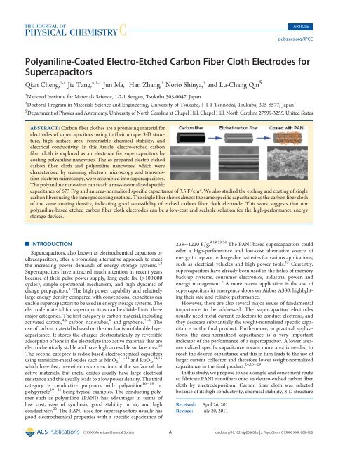
<strong>Polyaniline</strong>-<strong>Coated</strong> <strong>Electro</strong>-<strong>Etched</strong> <strong>Carbon</strong> <strong>Fiber</strong> <strong>Cloth</strong> <strong>Electro</strong>des for<br />
Supercapacitors<br />
Qian Cheng, †,‡ Jie Tang,* ,†,‡ Jun Ma, † Han Zhang, † Norio Shinya, † and Lu-Chang Qin §<br />
† National Institute for Materials Science, 1-2-1 Sengen, Tsukuba 305-0047, Japan<br />
‡ Doctoral Program in Materials Science and Engineering, University of Tsukuba, 1-1-1 Tennodai, Tsukuba, 305-8577, Japan<br />
§ Department of Physics and Astronomy, University of North Carolina at Chapel Hill, Chapel Hill, North Carolina 27599-3255, United States<br />
ABSTRACT: <strong>Carbon</strong> fiber clothes are a promising material for<br />
electrodes of supercapacitors owing to their unique 3-D structure,<br />
high surface area, remarkable chemical stability, and<br />
electrical conductivity. In this Article, electro-etched carbon<br />
fiber cloth is explored as an electrode for supercapacitors by<br />
coating polyaniline nanowires. The as-prepared electro-etched<br />
carbon fiber cloth and polyaniline nanowires, which were<br />
characterized by scanning electron microscopy and transmission<br />
electron microscopy, were assembled into supercapacitors.<br />
The polyaniline nanowires can reach a mass-normalized specific<br />
capacitance of 673 F/g and an area-normalized specific capacitance of 3.5 F/cm 2 . We also studied the etching and coating of single<br />
carbon fibers using the same processing method. The single fiber shows almost the same specific capacitance as the carbon fiber cloth<br />
of the same coating density, indicating good accessibility of etched carbon fiber cloth electrode. This work suggests that our<br />
polyaniline-based etched carbon fiber cloth electrodes can be a low-cost and scalable solution for the high-performance energy<br />
storage devices.<br />
’ INTRODUCTION<br />
Supercapacitors, also known as electrochemical capacitors or<br />
ultracapacitors, offer a promising alternative approach to meet<br />
the increasing power demands of energy storage systems. 1,2<br />
Supercapacitors have attracted much attention in recent years<br />
because of their pulse power supply, long cycle life (>100 000<br />
cycles), simple operational mechanism, and high dynamic of<br />
charge propagation. 3 The high power capability and relatively<br />
large energy density compared with conventional capacitors can<br />
enable supercapacitors to be used in energy storage systems. The<br />
electrode material for supercapacitors can be divided into three<br />
major categories. The first category is carbon material, including<br />
activated carbon, 4,5 carbon nanotubes, 6 and graphene. 7 9 The<br />
use of carbon material is based on the mechanism of double-layer<br />
capacitance. It stores the charges electrostatically by reversible<br />
adsorption of ions in the electrolyte into active materials that are<br />
electrochemically stable and have high accessible surface area. 10<br />
The second category is redox-based electrochemical capacitors<br />
11<br />
using transition-metal oxides such as MnO 13 2 and RuO 2 , 14,15<br />
which have fast, reversible redox reactions at the surface of the<br />
active materials. But metal oxides usually have large electrical<br />
resistance and this usually leads to a low power density. The third<br />
category is conductive polymers with polyaniline 16 18 or<br />
polypyrrole 19 21 being typical examples. The conducting polymer<br />
such as polyaniline (PANI) has advantages in terms of<br />
low cost, ease of synthesis, good stability in air, and high<br />
conductivity. 22 The PANI used for supercapacitors usually has<br />
good electrochemical properties with a specific capacitance of<br />
233 1220 F/g. 9,18,23,24 The PANI-based supercapacitors could<br />
offer a high-performance and low-cost alternative source of<br />
energy to replace rechargeable batteries for various applications,<br />
such as electrical vehicles and high power tools. 25 Currently,<br />
supercapacitors have already been used in the fields of memory<br />
back-up systems, consumer electronics, industrial power, and<br />
energy management. 2 A more recent application is the use of<br />
supercapacitors in emergency doors on Airbus A380, highlighting<br />
their safe and reliable performance.<br />
However, there are also several major issues of fundamental<br />
importance to be addressed. The supercapacitor electrodes<br />
usually need metal current collectors to conduct electrons, and<br />
they decrease substantially the weight-normalized specific capacitance<br />
in the final product. Furthermore, in practical applications,<br />
the area-normalized capacitance is a very important<br />
indicator of the performance of a supercapacitor. A lower areanormalized<br />
specific capacitance means more area is needed to<br />
reach the desired capacitance and this in turn leads to the use of<br />
larger current collector and therefore lower weight-normalized<br />
24,26 29<br />
capacitance in the final product.<br />
In this study, we propose to use a simple and convenient route<br />
to fabricate PANI nanofibers onto an electro-etched carbon fiber<br />
cloth by electrodeposition. <strong>Carbon</strong> fiber cloth was selected<br />
because of its high conductivity, chemical stability, 3-D structure<br />
Received: April 26, 2011<br />
Revised: July 20, 2011<br />
r XXXX American Chemical Society A dx.doi.org/10.1021/jp203852p | J. Phys. Chem. C XXXX, XXX, 000–000
The Journal of Physical Chemistry C<br />
of high porosity, and low cost. The porous structure of carbon<br />
fiber cloth is expected to facilitate the diffusion of electrolyte into<br />
the electrode material and to provide more channels for rapid ion<br />
transport. To examine the performance of carbon fibers, we<br />
also performed electro-etching and PANI coating of isolated<br />
single carbon fibers. Moreover, by growing PANI directly onto<br />
the electro-etched carbon fiber cloth electrodes, the electrodes<br />
are binder-free, and this can further reduce the interfacial<br />
resistance and enhance the electrochemical reaction rate. Most<br />
important of all, the carbon fiber cloth of high conductivity can<br />
also be used as the current collector to avoid using metal current<br />
collectors to increase the specific capacitance in practice. 28<br />
’ RESULTS AND DISCUSSION<br />
Our strategy is shown schematically in Figure 1. A carbon fiber<br />
cloth is first etched electrochemically to form a highly conductive<br />
substrate with high surface area. Then PANI nanofibers are<br />
coated onto the surface-etched carbon fiber cloth to form a 3-D<br />
structure. We expect this kind of nanostructured electrodes to<br />
Figure 1. Procedure for preparation of carbon electrodes and supercapacitor.<br />
<strong>Carbon</strong> fiber cloth was first etched by electro-etching. The<br />
etched carbon fiber cloth was then coated with PANI by electrodeposition.<br />
This kind of electrodes can be made into flexible structure that can<br />
be rolled into coiled foils.<br />
ARTICLE<br />
have both high weight-normalized and area-normalized specific<br />
capacitance.<br />
Scanning electron microscope (SEM) observations of PANI<br />
coated electro-etched carbon cloth are shown in Figure 2.<br />
Figure 2a is an SEM image of the carbon fiber cloth before<br />
etching. We can see that the carbon fibers are densely packed but<br />
randomly oriented to form a macroscopically open structure.<br />
This kind of open structure can offer better accessibility to the<br />
electrolyte. Furthermore, the carbon fiber cloth of high conductivity<br />
can also be used as flexible electrodes. Figure 2b shows a<br />
typical structure of the carbon fibers in the fiber cloth after<br />
electro-etching. The etched grooves will greatly increase the<br />
surface area. The electro-etched carbon fibers are easier for<br />
nucleation of monomers. Moreover, we also found that the<br />
electro-etched carbon fiber cloth is more hydrophilic than the<br />
one without etching. Figure 2c is the SEM morphology after<br />
PANI coating. The PANI nanofibers were grown on the electroetched<br />
carbon fibers quite uniformly. We can control the<br />
thickness of the PANI coating by adjusting the coating time.<br />
Figure 2d shows the PANI nanofibers at high magnification. The<br />
as-grown PANI nanofibers have an average length of 1 to 2 μm.<br />
The PANI nanofibers are packed randomly to form a mesoporous<br />
structure that would increase the rate of ion exchange.<br />
Figure 2e is a transmission electron microscope (TEM) image<br />
of a single PANI nanofiber. Figure 2f shows the nanofiber at<br />
higher resolution. We can see that the PANI nanofiber actually<br />
consisted of many small PANI nanorods. This is an ideal<br />
structure with high surface area for ion absorption.<br />
We found that etching is a very necessary step for making highperformance<br />
carbon fiber cloth electrodes. The comparison of<br />
electrochemical performance is shown in Figure 3a. The same<br />
PANI coating was carried out on two pieces of same carbon fiber<br />
clothes: one is electro-etched and the other is not. The electroetched<br />
piece exhibited a much larger cyclic voltammetric (CV)<br />
current than the pristine piece (Figure 3a), indicating a much<br />
larger specific capacitance. This is because the electro-etching<br />
process has increased the hydrophilicity that resulted in a more<br />
uniform coating on the whole carbon fiber cloth. This uniform<br />
coating would then enhance the accessibility of electrolyte. As a<br />
result, almost every PANI nanofiber can access the electrolyte<br />
and take part in the reactions with electrolyte. The carbon fiber<br />
Figure 2. (a) SEM image of the carbon fiber cloth. (b) <strong>Carbon</strong> fiber cloth after electro-etching. Grooves on the carbon fiber are due to electro-etching<br />
and the surface area is enlarged. (c) SEM image of electro-etched carbon fiber cloth after PANI coating. (d) SEM image reveals that the PANI coating is<br />
composed of tiny nanorods of PANI. (e) TEM image of a PANI nanowire. (f) High-resolution TEM image of PANI nanowire revealing that it is<br />
noncrystalline and is porous at the nanoscale.<br />
B dx.doi.org/10.1021/jp203852p |J. Phys. Chem. C XXXX, XXX, 000–000
The Journal of Physical Chemistry C<br />
ARTICLE<br />
Figure 3. (a) CV comparison of same amount of PANI coated on electro-etched and unetched carbon fiber cloth. (b) Charging and discharging curves of<br />
electro-etched carbon fiber cloth under various PANI coatings at constant charging current of 2 mA. (c) EIS curve of electro-etched carbon fiber cloth with<br />
and without PANI coating. (d) Cycling of PANI coated electrode under constant charging current of 20 mA. Inset is the CV curves before and after cycling.<br />
Figure 4. (a) Comparison of mass- and area-normalized specific capacitance under various PANI coating. (b) Specific capacitance with the carbon fiber<br />
cloth of various coating.<br />
cloth without electro-etching has poor hydrophilicity in the<br />
coating solution, and a thick PANI film is coated just on the<br />
carbon fiber cloth. This kind of thick film has poor efficiency in<br />
the use of the electrode material and results in a smaller CV<br />
current and therefore a lower specific capacitance.<br />
The coating density of the PANI coating can be controlled by<br />
the coating time. The charging and discharging curves at different<br />
coating densities are shown in Figure 3b. The discharge curves<br />
are almost linear in the total range of potential, which shows a<br />
very good capacitive behavior. 30 In the case of an electrochemical<br />
double-layer capacitor that only has an excess or deficiency of<br />
electron charges on the electrodes, no chemical changes are<br />
involved; therefore, symmetrical charging and discharging curves<br />
are expected. However, for a pseudocapacitor using material like<br />
conductive polymers or transition-metal oxides, redox reactions or<br />
insertion/removal of counterions must take place. Although the<br />
overall energy change can be conducted in a relatively reversible<br />
process thermodynamically, the charge and discharge processes<br />
in a pseudocapacitor often involve irreversibility in interconversion.<br />
Moreover, oxidation and reduction often take place at<br />
different potentials. As a result, we usually do not observe<br />
symmetrical charging and discharging curves for pseudocapacitors.<br />
In our case, the efficiency of pure carbon fiber cloth<br />
is ∼100% (electrochemical double-layer capacitance). The efficiency<br />
of PANI-coated carbon fiber cloth is 81.5%. We calculated<br />
the mass- and area-normalized specific capacitance, and the<br />
results are displayed in Figure 4a.<br />
Figure 3c is the Nyquist plot of impedance for the etched-electrode<br />
before and after PANI coating. In the complex-plane, Z2, the<br />
imaginary component (vertical), represents the capacitive properties,<br />
C dx.doi.org/10.1021/jp203852p |J. Phys. Chem. C XXXX, XXX, 000–000
The Journal of Physical Chemistry C<br />
and Z1, the real component, represents the ohmic properties. Both<br />
components were studied in the frequency range between 100<br />
kHz and 0.1 Hz. These plots usually consist of one or more<br />
semicircles in the complex plane, sometimes with the center of a<br />
semicircle depressed below the Z1 axis. Ideally, a Nyquist plot of<br />
a supercapacitor consists of three regions that are all dependent<br />
on the frequency. At high frequency, the supercapacitor behaves<br />
like a pure resistor. At low frequency, the imaginary part sharply<br />
increases and a vertical line is observed, indicating a pure<br />
capacitive behavior. In the medium frequency domain, the<br />
influence of the electrode porosities can be observed. When<br />
the frequency decreases, starting from the very high frequency,<br />
the electrolyte penetrates deeper and deeper into the porous<br />
structure of the electrode, then more and more electrode surface<br />
becomes available for ion adsorption. This medium frequency<br />
range is related to the electrolyte penetration inside the porous<br />
structure of the high porosity electrode, and this region is usually<br />
called the Warburg curve. 31 Both of the two lines in Figure 3c are<br />
nearly linear in the low-frequency region and show a very small<br />
arc in the high-frequency region. This loop shift is related to the<br />
electric resistance between the PANI and carbon fiber cloth. The<br />
semicircular loop has been observed routinely in carbon-based<br />
supercapacitors. There is usually a very large loop in the supercapacitors<br />
of activated carbon electrodes, which means large<br />
intergranular electric resistance between the activated carbon<br />
particles. It mainly depends on the electrode surface area and the<br />
interparticle resistivity. The use of thin active layers or adding<br />
some low surface area conductive additives can reduce this value<br />
but will lead to a low capacitance per area or per weight. The loop<br />
may also reveal correlations between the active material and the<br />
current collector. The very small loop regions in Figure 3c<br />
indicate a very low electrical resistance between the PANI<br />
nanofibers and good interfacial conductivity between the PANI<br />
nanofibers and the carbon fibers of the cloth. The Warburg<br />
curves in Figure 3c are very short, indicating good accessbility of<br />
electrolyte ions to the PANI nanofibers. The equivalent series<br />
resistance (ESR) is obtained from the Z1-intercept in the<br />
Nyquist plot (Figure 3c), and they are 2.3 Ω and 1.75 Ω,<br />
respectively. We noticed that the ESR decreased after we made<br />
PANI coating on the carbon fiber cloth. The conductivity of<br />
carbon fiber cloth is one order of magnitude greater than<br />
PANI. However, in the carbon fiber cloth, because the carbon<br />
fibers are stacked together and the point of contact of the<br />
carbon fiber may increase the resistance, the coating of conductive<br />
polymer could enlarge the contact area for each fiber,<br />
which would in turn decrease the resistance. The ESR data<br />
determined the rate that the supercapacitor can be charged and<br />
discharged, and it is a very important factor to determine the<br />
power density of a supercapacitor.<br />
Figure 3d shows the cycling property of PANI-coated carbon<br />
fiber cloth under the charging current of 20 mA. We coated<br />
different densities of PANI onto the etched carbon fiber cloth of<br />
1.8, 3.6, 5.4, 7.2, and 9.0 mg/cm 2 . The cyclicity shown in<br />
Figure 3d is obtained with a coating density of 1.8 mg/cm 2 ,<br />
which is the smallest coating density. The capacitance dropped<br />
less than 10% after 1000 cycles, indicating good cyclability of the<br />
electrodes. The inserted graph is the CV curve before and after<br />
long time cycling. It should be noted that in the first 500 cycles a<br />
large drop in specific capacitance is usually observed, and the<br />
specific capacitance becomes relatively stable afterward. In our<br />
case, the specific capacitance dropped around 7% in the first 500<br />
cycles, and it dropped less than 3% in the last 500 cycles. We also<br />
ARTICLE<br />
Figure 5. (a) SEM image of a single carbon fiber without etching.<br />
(b) SEM image of the same carbon fiber after electro-etching. (c) <strong>Etched</strong><br />
carbon fiber after PANI coating.<br />
tested the cyclicality of larger coating densities, which exhibited<br />
almost the same behavior, but we should note that the cyclicality<br />
of high coating density like 9 mg/cm 2 became a little worse; it<br />
dropped ∼15% after 1000 cycles. This is because for a thick<br />
PANI coating, some PANI may have fallen from the carbon fiber<br />
cloth to the separator to result in a lower capacitance.<br />
The mass- and area-normalized specific capacitance under<br />
different coating densities were calculated from the charging and<br />
discharging curve, which is shown in Figure 4a. We could see that<br />
the mass-normalized capacitance decreased when the coating<br />
density is increased. The higher coating density means thicker<br />
PANI coating. We obtained a high mass-normalized specific<br />
capacitance of 1026.8 F/g at the PANI coating density of 1.8 mg/cm 2 .<br />
However, we only reached 265.9 F/g when the coating density<br />
was 9 mg/cm 2 . This is because only the PANI on or near the<br />
surface could participate the redox reactions. Some of the PANI<br />
was not utilized when the PANI coating layer is thick. The areanormalized<br />
specific capacitance, which is a very important indicator<br />
of the performance of supercapacitor, is also studied in this<br />
work. Most electrodes with low loading of active materials can<br />
achieve high mass-normalized specific capacitance but often poor<br />
area-normalized capacitance. This kind of supercapacitor is not<br />
suitable for practical applications. Achieving both high massnormalized<br />
capacitance and area-normalized capacitance for<br />
electrodes is crucial for practical applications. We obtained<br />
specific capacitance of 5.4 F/cm 2 when the PANI coating was<br />
9.0 mg/cm 2 . We optimized the coating time to 10 min and<br />
obtained a mass-normalized specific capacitance of 1026.8 F/g<br />
and an area-normalized specific capacitance of 1.4 F/cm 2 with a<br />
coating density of 1.8 mg/cm 2 . We also obtained mass-specific<br />
capacitance of 673 F/g and area-normalized specific capacitance<br />
of 3.5 F/cm 2 when we controlled the coating time to 30 min with<br />
a coating density of 5.4 mg/cm 2 . The high conductive carbon<br />
fiber cloth can also be used as the current collector to avoid using<br />
metal current collectors.<br />
It is interesting to compare our electrodes with PANI-carbon<br />
nanotube composite electrodes. Gupta et al. successfully synthesized<br />
a PANI and single-walled carbon nanotube (SWCNT)<br />
composite electrode and obtained a mass-normalized specific<br />
capacitance of 463 F/g of and an area-normalized specific capacitance<br />
of 2.7 F/cm 2 . 18 PANI and multiwalled carbon nanotube<br />
composite electrode was synthesized by in situ chemical polymerization,<br />
and a high initial mass-normalized specific capacitance of<br />
606 F/g was obtained. 24 Zhang et al. successfully deposited PANI<br />
onto vertically aligned carbon nanotubes for preparing supercapacitors,<br />
and a high mass-normalized specific capacitance of<br />
1030 F/g was obtained, although it could only reach a rather low<br />
area-normalized specific capacitance of 1.4 F/cm 2 . 23 As previously<br />
D dx.doi.org/10.1021/jp203852p |J. Phys. Chem. C XXXX, XXX, 000–000
The Journal of Physical Chemistry C<br />
ARTICLE<br />
Figure 6. <strong>Electro</strong>chemical properties of a single carbon fiber. (a) CV curves of the carbon fiber before and after electro-etching. (b) CV curves of the<br />
single fiber before and after PANI coating. (c) Charging and discharging curves of PANI-coated single carbon fiber under different charging current.<br />
(d) Specific capacitance of the PANI coating and the PANI coating together with the carbon fiber under different charging current.<br />
mentioned, the carbon fiber cloth can also be used as the current<br />
collector to avoid using metal current collectors. The total specific<br />
capacitance with carbon fiber cloth under different coating densities<br />
is shown in Figure 4b. The specific capacitance is nearly 200<br />
F/g using the carbon fiber cloth as current collector, underlining<br />
the potential for practical applications of the electrodes.<br />
To understand and evaluate the performance of carbon fibers,<br />
we also applied the same processing to isolated single carbon<br />
fibers, as illustrated in Figure 5. A single carbon fiber was first<br />
picked up and mounted onto the platinum substrate. The<br />
morphology of the pristine carbon fiber is shown in Figure 5a.<br />
The single fiber was etched in the same acid solution for the same<br />
amount of time, leading to the structure shown in Figure 5b. The<br />
electro-etched carbon fiber was then coated with the same PANI<br />
nanofibers, as shown in Figure 5c.<br />
The electrochemical performance of the single carbon fiber<br />
before and after PANI coating is shown in Figure 6. As previously<br />
reasoned, the etched carbon fiber increased the surface area to<br />
raise the double-layer capacitance, and this is confirmed by the<br />
electrochemical properties of the structure shown in Figure 6a.<br />
The carbon fiber before etching shows very small current<br />
response in the CV curve. In contrast, the carbon fiber after<br />
etching shows a much larger current than the one without<br />
etching. In the case of a pure carbon material, the specific<br />
capacitance, which is proportional to the CV current, is only<br />
dependent on the surface area. This means that the surface area<br />
has increased greatly after etching. Figure 6b is the CV curve of<br />
the single carbon fiber before and after PANI coating at the<br />
density of 5.4 mg/cm 2 . The CV current increased greatly after<br />
PANI coating, indicating an increase in the capacitance because<br />
the PANI coating and the redox reaction of PANI are the main<br />
contributions to the whole capacitance. The shape of the CV<br />
curve is close to rectangular, indicating an excellent capacitance<br />
behavior and a low contact resistance. The charging and discharging<br />
curves in different charging currents are shown in Figure 6c.<br />
The specific capacitance of the PANI coating alone as well as the<br />
PANI coating together with the carbon fibers was calculated on<br />
the charging and discharging curves, which are shown in<br />
Figure 6d. The specific capacitance of the PANI is 677 F/g,<br />
almost the same as that of the carbon fiber cloth with PANI<br />
coating (673 F/g) of the same coating parameter. We know that<br />
the single fiber can be fully accessed by and reacted with the<br />
electrolyte. The almost same specific capacitance of the single<br />
fiber compared with carbon fiber cloth electrode indicates a very<br />
good accessibility of the PANI-coated carbon fiber cloth electrode.<br />
This result is attributed to the 3-D macroscopically open<br />
structure of the carbon fiber cloth and the mesoporous structure<br />
of PANI nanofibers.<br />
Charged supercapacitors, like charged batteries, are in a state<br />
of high free energy relative to that of the discharged state, so there<br />
is a pseudodriving force for their self-discharge. The self-discharge<br />
characteristics of a supercapacitor device are important in evaluating<br />
its performance and commercial specifications. When supercapacitors<br />
or batteries are charged and then left on open circuit for<br />
some time, a certain degree of self-discharge can set in, which<br />
depends on the chemistry and electrochemistry of the system, the<br />
purity of reagents and electrolytes, and so on. Charged supercapacitors<br />
usually exhibit greater rates of self-dicharge than most<br />
E dx.doi.org/10.1021/jp203852p |J. Phys. Chem. C XXXX, XXX, 000–000
The Journal of Physical Chemistry C<br />
ARTICLE<br />
density, indicating the good accessibility of the etched carbon<br />
fiber cloth electrodes.<br />
Figure 7. Self-discharge of PANI-coated carbon fiber cloth supercapacitor.<br />
batteries at a given temperature. This difference in stability of<br />
voltage is attributable to the fact that the potential of battery<br />
electrodes is usually thermodynamically determined at some<br />
equilibrium open-circuit value that is characterized by an exchange<br />
current density corresponding to an electrostatically<br />
determined potential difference that has no mechanism thermodynamically<br />
and kinetically stabilizing it. Hence the potential can<br />
be easily disturbed by some adventitious depolarizing process set,<br />
for example, in impurities or surface redox groups. In the case of a<br />
charged pseudocapacitor, the self-discharge mechanism must<br />
involve a dissipation of the double-layer charge coupled to<br />
diminution of the coverage on the electrode surface because<br />
the charge for formation or removal of such an electroactive<br />
species is normally substantially larger than that for charging or<br />
discharging the double-layer capacitance. 32 We charged our<br />
PANI-coated carbon fiber cloth supercapacitor to 1.0 V and then<br />
left on open circuit for 50 000 s (∼14 h) at room temperature;<br />
the self-discharge associated with a fall in potential takes place<br />
over a long period, which can be seen in Figure 7. It dropped<br />
∼50% after the first 1 h and eventfully reached a steady potential<br />
of ∼0.24 V.<br />
Our results indicate that the carbon fiber cloth electrode can<br />
be a promising candidate for uses in electric or hybrid vehicles.<br />
Furthermore, the results are also of potential use for the<br />
preparation of PANI-based electrodes with varied properties to<br />
meet diverse applications, such as lithium ion batteries, electrochemical<br />
sensors, and solar cells.<br />
’ CONCLUSIONS<br />
We have successfully fabricated PANI-coated electro-etched<br />
carbon fiber cloth electrodes for supercapacitors that give rise to a<br />
remarkable result of weight-normalized specific capacitance of<br />
673 F/g. What’s more, the high value of area-normalized specific<br />
capacitance of 3.5 F/cm 2 is crucial for their practical applications.<br />
The electro-etching process is very important for making the<br />
carbon fiber cloth electrodes effective and efficient. First, the<br />
electro-etching process can greatly increase the surface area of<br />
the carbon fiber cloth. Second, the etching process can increase<br />
the hydrophilicity of the carbon fiber cloth and make it easier for<br />
uniform PANI coating. Moreover, the coating of PANI can<br />
decrease the electrical resistance of the electrodes. We also<br />
studied single carbon fibers under the same processing procedure.<br />
The single carbon fiber showed almost the same specific<br />
capacitance as the carbon fiber cloth with the same coating<br />
’ METHOD<br />
The carbon fiber cloth with a thickness of 0.19 mm was<br />
purchased commercially from TORAY. The mass density of the<br />
carbon fiber cloth is 0.44 g/cm 3 . The average diameter of each<br />
carbon fiber is 8 μm. The aniline and sulfuric acid were of<br />
analytical reagent grade from Sigma-Aldrich.<br />
The electro-etching of carbon fiber cloth was conducted using<br />
a potentialstat operated at 2 V for 10 min in 1M H 2 SO 4 electrolyte.<br />
The electro-etched carbon fiber cloth (0.5 2 cm) was used as the<br />
working electrode, and a platinum sheet (1 2cm 2 )wasusedas<br />
the counter electrode. All potential values were recorded versus the<br />
saturated Ag/AgCl reference electrode. The distance between the<br />
working electrode and counter electrode was fixed at 1.5 cm.<br />
Anodic deposition was controlled by an electrochemical station<br />
(IVIUM Technologies) in a 1 M HCl electrolyte containing<br />
0.3 M aniline monomer. 26 The PANI nanowires were synthesized<br />
by a two-step method on a conventional three-electrode<br />
system. The first step is the nucleation of PANI, performed at a<br />
constant potential of 0.8 V for 1 min at room temperature. After<br />
that, the nanowires were grown under a constant current condition<br />
with current density of 5 mA/cm 2 .<br />
The electrochemical properties and capacitance measurement<br />
of the supercapacitor electrodes were studied in a three-electrode<br />
system by CV and electrochemical impedance spectroscopy<br />
(EIS) using CompactStat of Ivium Technologies. The CV<br />
response of the electrodes was measured at different scan rates<br />
varying from 10 to 100 mV/s. Voltammetry testing was carried<br />
out at potentials between 0 and 0.8 V in 1 M H 2 SO 4 aqueous<br />
electrolyte solution. Impedance spectroscopy measurements<br />
were carried out without DC bias sinusoidal signal of 0.005 V<br />
over the frequency range from 100 kHz to 0.1 Hz.<br />
We calculated the area-normalized specific capacitance by<br />
using the total electrode capacitance divided by the apparent<br />
carbon fiber cloth area, which is 1 cm 2 . The weight-normalized<br />
specific capacitance is calculated by the total capacitance divided<br />
by electrode weight, which is measured by an analytical balance<br />
(XP205, 0.01 mg).<br />
The morphology and structure of the electrodes were examined<br />
by SEM (JSM-6500F, JEOL) and TEM (JEM-2100, JEOL).<br />
’ AUTHOR INFORMATION<br />
Corresponding Author<br />
*E-mail: tang.jie@nims.go.jp.<br />
’ ACKNOWLEDGMENT<br />
This work was supported by JSPS Grants-in-Aid for Scientific<br />
Research No.19310081 and 22310074, JST ALCA Program, and<br />
the Nanotechnology Network Project of the Ministry of Education,<br />
Culture, Sports, Science and Technology (MEXT), Japan.<br />
’ REFERENCES<br />
(1) Simon, P.; Gogotsi, Y. Materials for electrochemical capacitors.<br />
Nat. Mater. 2008, 7, 845–854.<br />
(2) Miller, J. R.; Simon, P. Materials science - <strong>Electro</strong>chemical<br />
capacitors for energy management. Science 2008, 321, 651–652.<br />
(3) Zhang, L. L.; Zhao, X. S. <strong>Carbon</strong>-based materials as supercapacitor<br />
electrodes. Chem. Soc. Rev. 2009, 38, 2520–2531.<br />
F dx.doi.org/10.1021/jp203852p |J. Phys. Chem. C XXXX, XXX, 000–000
The Journal of Physical Chemistry C<br />
(4) Frackowiak, E.; Beguin, F. <strong>Carbon</strong> materials for the electrochemical<br />
storage of energy in capacitors. <strong>Carbon</strong> 2001, 39, 937–950.<br />
(5) Frackowiak, E.; Beguin, F. <strong>Electro</strong>chemical storage of energy in<br />
carbon nanotubes and nanostructured carbons. <strong>Carbon</strong> 2002, 40,<br />
1775–1787.<br />
(6) Futaba, D. N.; Hata, K.; Yamada, T.; Hiraoka, T.; Hayamizu, Y.;<br />
Kakudate, Y.; Tanaike, O.; Hatori, H.; Yumura, M.; Iijima, S. Shapeengineerable<br />
and highly densely packed single-walled carbon nanotubes<br />
and their application as super-capacitor electrodes. Nat. Mater. 2006,<br />
5, 987–994.<br />
(7) Wang, Y.; Shi, Z. Q.; Huang, Y.; Ma, Y. F.; Wang, C. Y.; Chen,<br />
M. M.; Chen, Y. S. Supercapacitor devices based on graphene materials.<br />
J. Phys. Chem. C 2009, 113, 13103–13107.<br />
(8) Stoller, M. D.; Park, S. J.; Zhu, Y. W.; An, J. H.; Ruoff, R.S.<br />
Graphene-based ultracapacitors. Nano Lett. 2008, 8, 3498–3502.<br />
(9) Wang, D. W.; Li, F.; Zhao, J. P.; Ren, W. C.; Chen, Z. G.; Tan, J.;<br />
Wu, Z. S.; Gentle, I.; Lu, G. Q.; Cheng, H. M. Fabrication of graphene/<br />
polyaniline composite paper via in situ anodic electropolymerization for<br />
high-performance flexible electrode. ACS Nano 2009, 3, 1745–1752.<br />
(10) Pandolfo, A. G.; Hollenkamp, A. F. <strong>Carbon</strong> properties and their<br />
role in supercapacitors. J. Power Sources 2006, 157, 11–27.<br />
(11) Fischer, A. E.; Pettigrew, K. A.; Rolison, D. R.; Stroud, R. M.;<br />
Long, J. W. Incorporation of homogeneous, nanoscale MnO 2 within<br />
ultraporous carbon structures via self-limiting electroless deposition:<br />
Implications for electrochemical capacitors. Nano Lett. 2007, 7, 281–286.<br />
(12) Chang, J. K.; Lee, M. T.; Tsai, W. T.; Deng, M. J.; Cheng, H. F.;<br />
Sun, I. W. Pseudocapacitive mechanism of manganese oxide in 1-ethyl-3-<br />
methytimidazolium thiocyanate ionic liquid electrolyte studied using<br />
X-ray photoelectron spectroscopy. Langmuir 2009, 25, 11955–11960.<br />
(13) Babakhani, B.; Ivey, D. G. Anodic deposition of manganese<br />
oxide electrodes with rod-like structures for application as electrochemical<br />
capacitors. J. Power Sources 2010, 195, 2110–2117.<br />
(14) Conway, B. E. Transition from Supercapacitor to Battery<br />
Behavior in <strong>Electro</strong>chemical Energy-Storage. J. <strong>Electro</strong>chem. Soc. 1991,<br />
138, 1539–1548.<br />
(15) Long, J. W.; Swider, K. E.; Merzbacher, C. I.; Rolison, D. R.<br />
Voltammetric characterization of ruthenium oxide-based aerogels and<br />
other RuO 2 solids: the nature of capacitance in nanostructured materials.<br />
Langmuir 1999, 15, 780–785.<br />
(16) Frackowiak, E.; Khomenko, V.; Jurewicz, K.; Lota, K.; Beguin,<br />
F. Supercapacitors based on conducting polymers/nanotubes composites.<br />
J. Power Sources 2006, 153, 413–418.<br />
(17) Ryu, K. S.; Kim, K. M.; Park, N. G.; Park, Y. J.; Chang, S. H.<br />
Symmetric redox supercapacitor with conducting polyaniline electrodes.<br />
J. Power Sources 2002, 103, 305–309.<br />
(18) Gupta, V.; Miura, N. Influence of the microstructure on the<br />
supercapacitive behavior of polyaniline/single-wall carbon nanotube<br />
composites. J. Power Sources 2006, 157, 616–620.<br />
(19) Khomenko, V.; Frackowiak, E.; Beguin, F. Determination of the<br />
specific capacitance of conducting polymer/nanotubes composite electrodes<br />
using different cell configurations. <strong>Electro</strong>chim. Acta 2005, 50,<br />
2499–2506.<br />
(20) Park, J. H.; Ko, J. M.; Park, O. O.; Kim, D. W. Capacitance<br />
properties of graphite/polypyrrole composite electrode prepared by<br />
chemical polymerization of pyrrole on graphite fiber. J. Power Sources<br />
2002, 105, 20–25.<br />
(21) Li, J.; Cui, L.; Zhang, X. G. Preparation and electrochemistry of<br />
one-dimensional nanostructured MnO 2 /PPy composite for electrochemical<br />
capacitor. Appl. Surf. Sci. 2010, 256, 4339–4343.<br />
(22) Lacroix, J. C.; Diaz, A. F. <strong>Electro</strong>lyte effects on the switching<br />
reaction of polyaniline. J. <strong>Electro</strong>chem. Soc. 1988, 135, 1457–1463.<br />
(23) Zhang, H.; Cao, G. P.; Wang, Z. Y.; Yang, Y. S.; Shi, Z. J.; Gu,<br />
Z. N. Tube-covering-tube nanostructured polyaniline/carbon nanotube<br />
array composite electrode with high capacitance and superior rate<br />
performance as well as good cycling stability. <strong>Electro</strong>chem. Commun.<br />
2008, 10, 1056–1059.<br />
(24) Sivakkumar, S. R.; Kim, W. J.; Choi, J. A.; MacFarlane, D. R.;<br />
Forsyth, M.; Kim, D. W. <strong>Electro</strong>chemical performance of polyaniline<br />
ARTICLE<br />
nanofibres and polyaniline/multi-walled carbon nanotube composite as<br />
an electrode material for aqueous redox supercapacitors. J. Power Sources<br />
2007, 171, 1062–1068.<br />
(25) Tarascon, J. M.; Armand, M. Issues and challenges facing<br />
rechargeable lithium batteries. Nature 2001, 414, 359–367.<br />
(26) Yu, X. F.; Li, Y. X.; Zhu, N. F.; Yang, Q. B.; Kalantar-zadeh, K. A<br />
polyaniline nanofibre electrode and its application in a self-powered<br />
photoelectrochromic cell. Nanotechnology 2007, 18, -.<br />
(27) Wang, K.; Huang, J. Y.; Wei, Z. X. Conducting polyaniline<br />
nanowire arrays for high performance supercapacitors. J. Phys. Chem. C<br />
2010, 114, 8062–8067.<br />
(28) Horng, Y. Y.; Lu, Y. C.; Hsu, Y. K.; Chen, C. C.; Chen, L. C.;<br />
Chen, K. H. Flexible supercapacitor based on polyaniline nanowires/<br />
carbon cloth with both high gravimetric and area-normalized capacitance.<br />
J. Power Sources 2010, 195, 4418–4422.<br />
(29) Wang, H. L.; Hao, Q. L.; Yang, X. J.; Lu, L. D.; Wang, X.<br />
Graphene oxide doped polyaniline for supercapacitors. <strong>Electro</strong>chem.<br />
Commun. 2009, 11, 1158–1161.<br />
(30) Qu, D. Y. Studies of the activated carbons used in double-layer<br />
supercapacitors. J. Power Sources 2002, 109, 403–411.<br />
(31) Portet, C.; Taberna, P. L.; Simon, P.; Laberty-Robert, C.<br />
Modification of Al current collector surface by sol-gel deposit for<br />
carbon-carbon supercapacitor applications. <strong>Electro</strong>chim. Acta 2004, 49,<br />
905–912.<br />
(32) Conway, B. E. <strong>Electro</strong>chemical Supercapacitors: Scientific Fundamentals<br />
and Technological Applications; Plenum Press: New York, 1999;<br />
p 698.<br />
’ NOTE ADDED AFTER ASAP PUBLICATION<br />
This manuscript was originally published on the web on<br />
November 1, 2011, with errors to the Results and Discussion<br />
Section and the caption of Figure 2. The corrected version was<br />
reposted on November 4, 2011.<br />
G dx.doi.org/10.1021/jp203852p |J. Phys. Chem. C XXXX, XXX, 000–000