Polyaniline-Coated Electro-Etched Carbon Fiber Cloth Electrodes ...
Polyaniline-Coated Electro-Etched Carbon Fiber Cloth Electrodes ...
Polyaniline-Coated Electro-Etched Carbon Fiber Cloth Electrodes ...

Create successful ePaper yourself
Turn your PDF publications into a flip-book with our unique Google optimized e-Paper software.
The Journal of Physical Chemistry C<br />
and Z1, the real component, represents the ohmic properties. Both<br />
components were studied in the frequency range between 100<br />
kHz and 0.1 Hz. These plots usually consist of one or more<br />
semicircles in the complex plane, sometimes with the center of a<br />
semicircle depressed below the Z1 axis. Ideally, a Nyquist plot of<br />
a supercapacitor consists of three regions that are all dependent<br />
on the frequency. At high frequency, the supercapacitor behaves<br />
like a pure resistor. At low frequency, the imaginary part sharply<br />
increases and a vertical line is observed, indicating a pure<br />
capacitive behavior. In the medium frequency domain, the<br />
influence of the electrode porosities can be observed. When<br />
the frequency decreases, starting from the very high frequency,<br />
the electrolyte penetrates deeper and deeper into the porous<br />
structure of the electrode, then more and more electrode surface<br />
becomes available for ion adsorption. This medium frequency<br />
range is related to the electrolyte penetration inside the porous<br />
structure of the high porosity electrode, and this region is usually<br />
called the Warburg curve. 31 Both of the two lines in Figure 3c are<br />
nearly linear in the low-frequency region and show a very small<br />
arc in the high-frequency region. This loop shift is related to the<br />
electric resistance between the PANI and carbon fiber cloth. The<br />
semicircular loop has been observed routinely in carbon-based<br />
supercapacitors. There is usually a very large loop in the supercapacitors<br />
of activated carbon electrodes, which means large<br />
intergranular electric resistance between the activated carbon<br />
particles. It mainly depends on the electrode surface area and the<br />
interparticle resistivity. The use of thin active layers or adding<br />
some low surface area conductive additives can reduce this value<br />
but will lead to a low capacitance per area or per weight. The loop<br />
may also reveal correlations between the active material and the<br />
current collector. The very small loop regions in Figure 3c<br />
indicate a very low electrical resistance between the PANI<br />
nanofibers and good interfacial conductivity between the PANI<br />
nanofibers and the carbon fibers of the cloth. The Warburg<br />
curves in Figure 3c are very short, indicating good accessbility of<br />
electrolyte ions to the PANI nanofibers. The equivalent series<br />
resistance (ESR) is obtained from the Z1-intercept in the<br />
Nyquist plot (Figure 3c), and they are 2.3 Ω and 1.75 Ω,<br />
respectively. We noticed that the ESR decreased after we made<br />
PANI coating on the carbon fiber cloth. The conductivity of<br />
carbon fiber cloth is one order of magnitude greater than<br />
PANI. However, in the carbon fiber cloth, because the carbon<br />
fibers are stacked together and the point of contact of the<br />
carbon fiber may increase the resistance, the coating of conductive<br />
polymer could enlarge the contact area for each fiber,<br />
which would in turn decrease the resistance. The ESR data<br />
determined the rate that the supercapacitor can be charged and<br />
discharged, and it is a very important factor to determine the<br />
power density of a supercapacitor.<br />
Figure 3d shows the cycling property of PANI-coated carbon<br />
fiber cloth under the charging current of 20 mA. We coated<br />
different densities of PANI onto the etched carbon fiber cloth of<br />
1.8, 3.6, 5.4, 7.2, and 9.0 mg/cm 2 . The cyclicity shown in<br />
Figure 3d is obtained with a coating density of 1.8 mg/cm 2 ,<br />
which is the smallest coating density. The capacitance dropped<br />
less than 10% after 1000 cycles, indicating good cyclability of the<br />
electrodes. The inserted graph is the CV curve before and after<br />
long time cycling. It should be noted that in the first 500 cycles a<br />
large drop in specific capacitance is usually observed, and the<br />
specific capacitance becomes relatively stable afterward. In our<br />
case, the specific capacitance dropped around 7% in the first 500<br />
cycles, and it dropped less than 3% in the last 500 cycles. We also<br />
ARTICLE<br />
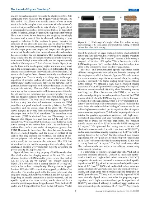
Figure 5. (a) SEM image of a single carbon fiber without etching.<br />
(b) SEM image of the same carbon fiber after electro-etching. (c) <strong>Etched</strong><br />
carbon fiber after PANI coating.<br />
tested the cyclicality of larger coating densities, which exhibited<br />
almost the same behavior, but we should note that the cyclicality<br />
of high coating density like 9 mg/cm 2 became a little worse; it<br />
dropped ∼15% after 1000 cycles. This is because for a thick<br />
PANI coating, some PANI may have fallen from the carbon fiber<br />
cloth to the separator to result in a lower capacitance.<br />
The mass- and area-normalized specific capacitance under<br />
different coating densities were calculated from the charging and<br />
discharging curve, which is shown in Figure 4a. We could see that<br />
the mass-normalized capacitance decreased when the coating<br />
density is increased. The higher coating density means thicker<br />
PANI coating. We obtained a high mass-normalized specific<br />
capacitance of 1026.8 F/g at the PANI coating density of 1.8 mg/cm 2 .<br />
However, we only reached 265.9 F/g when the coating density<br />
was 9 mg/cm 2 . This is because only the PANI on or near the<br />
surface could participate the redox reactions. Some of the PANI<br />
was not utilized when the PANI coating layer is thick. The areanormalized<br />
specific capacitance, which is a very important indicator<br />
of the performance of supercapacitor, is also studied in this<br />
work. Most electrodes with low loading of active materials can<br />
achieve high mass-normalized specific capacitance but often poor<br />
area-normalized capacitance. This kind of supercapacitor is not<br />
suitable for practical applications. Achieving both high massnormalized<br />
capacitance and area-normalized capacitance for<br />
electrodes is crucial for practical applications. We obtained<br />
specific capacitance of 5.4 F/cm 2 when the PANI coating was<br />
9.0 mg/cm 2 . We optimized the coating time to 10 min and<br />
obtained a mass-normalized specific capacitance of 1026.8 F/g<br />
and an area-normalized specific capacitance of 1.4 F/cm 2 with a<br />
coating density of 1.8 mg/cm 2 . We also obtained mass-specific<br />
capacitance of 673 F/g and area-normalized specific capacitance<br />
of 3.5 F/cm 2 when we controlled the coating time to 30 min with<br />
a coating density of 5.4 mg/cm 2 . The high conductive carbon<br />
fiber cloth can also be used as the current collector to avoid using<br />
metal current collectors.<br />
It is interesting to compare our electrodes with PANI-carbon<br />
nanotube composite electrodes. Gupta et al. successfully synthesized<br />
a PANI and single-walled carbon nanotube (SWCNT)<br />
composite electrode and obtained a mass-normalized specific<br />
capacitance of 463 F/g of and an area-normalized specific capacitance<br />
of 2.7 F/cm 2 . 18 PANI and multiwalled carbon nanotube<br />
composite electrode was synthesized by in situ chemical polymerization,<br />
and a high initial mass-normalized specific capacitance of<br />
606 F/g was obtained. 24 Zhang et al. successfully deposited PANI<br />
onto vertically aligned carbon nanotubes for preparing supercapacitors,<br />
and a high mass-normalized specific capacitance of<br />
1030 F/g was obtained, although it could only reach a rather low<br />
area-normalized specific capacitance of 1.4 F/cm 2 . 23 As previously<br />
D dx.doi.org/10.1021/jp203852p |J. Phys. Chem. C XXXX, XXX, 000–000