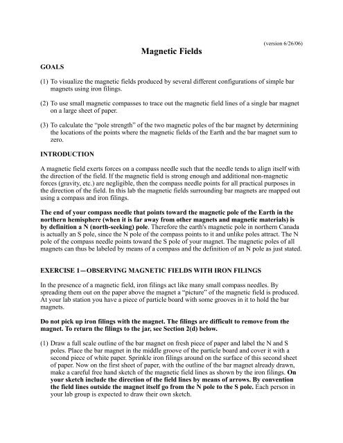
Magnetic Fields
Magnetic Fields
Magnetic Fields

Create successful ePaper yourself
Turn your PDF publications into a flip-book with our unique Google optimized e-Paper software.
<strong>Magnetic</strong> <strong>Fields</strong><br />
(version 6/26/06)<br />
GOALS<br />
(1) To visualize the magnetic fields produced by several different configurations of simple bar<br />
magnets using iron filings.<br />
(2) To use small magnetic compasses to trace out the magnetic field lines of a single bar magnet<br />
on a large sheet of paper.<br />
(3) To calculate the “pole strength” of the two magnetic poles of the bar magnet by determining<br />
the locations of the points where the magnetic fields of the Earth and the bar magnet sum to<br />
zero.<br />
INTRODUCTION<br />
A magnetic field exerts forces on a compass needle such that the needle tends to align itself with<br />
the direction of the field. If the magnetic field is strong enough and additional non-magnetic<br />
forces (gravity, etc.) are negligible, then the compass needle points for all practical purposes in<br />
the direction of the field. In this lab the magnetic fields surrounding bar magnets are mapped out<br />
using a compass and iron filings.<br />
The end of your compass needle that points toward the magnetic pole of the Earth in the<br />
northern hemisphere (when it is far away from other magnets and magnetic materials) is<br />
by definition a N (north-seeking) pole. Therefore the earth's magnetic pole in northern Canada<br />
is actually an S pole, since the N pole of the compass points to it and unlike poles attract. The N<br />
pole of the compass needle points toward the S pole of your magnet. The magnetic poles of all<br />
magnets can thus be labeled by means of a compass and the definition of an N pole as just stated.<br />
EXERCISE 1—OBSERVING MAGNETIC FIELDS WITH IRON FILINGS<br />
In the presence of a magnetic field, iron filings act like many small compass needles. By<br />
spreading them out on the paper above the magnet a “picture” of the magnetic field is produced.<br />
At your lab station you have a piece of particle board with some grooves in it to hold the bar<br />
magnets.<br />
Do not pick up iron filings with the magnet. The filings are difficult to remove from the<br />
magnet. To return the filings to the jar, see Section 2(d) below.<br />
(1) Draw a full scale outline of the bar magnet on fresh piece of paper and label the N and S<br />
poles. Place the bar magnet in the middle groove of the particle board and cover it with a<br />
second piece of white paper. Sprinkle iron filings around on the surface of this second sheet<br />
of paper. Now on the first sheet of paper, with the outline of the bar magnet already drawn,<br />
make a careful free hand sketch of the magnetic field lines as shown by the iron filings. On<br />
your sketch include the direction of the field lines by means of arrows. By convention<br />
the field lines outside the magnet itself go from the N pole to the S pole. Each person in<br />
your lab group is expected to draw their own sketch.
(2) Now repeat this process for the following configurations of bar magnets. In each case sketch<br />
the magnetic field lines and indicate the direction of the field lines everywhere on your<br />
sketch.<br />
(a) Place two bar magnets end-to-end in the same groove along the middle of the particle<br />
board with their N poles several centimeters apart.<br />
(b) Place two bar magnets side by side in parallel grooves with either like poles near or<br />
unlike poles near each other.<br />
(c) Pick another configuration of your choice.<br />
(d) To pick up the iron filings, do not use the magnet! Place the jar on a clean piece of<br />
paper and open the lid. Filings often will spill out from under the lid. Gently lift the paper<br />
with filings off of the magnet. Let the paper sag to make a funnel of sorts, and then pour<br />
the filings into the jar. Replace the jar cover.<br />
(3) Analyze your data.<br />
(a) Describe the general characteristics of the field that you observe.<br />
(b) On your sketches label by some means the regions where the magnetic field is especially<br />
strong and especially weak for each configuration. Are there any points where the field is<br />
essentially zero? Identify these locations clearly as well. Be sure to include the reasoning<br />
behind your answers.<br />
(c) Can you find any places where the magnetic field lines cross? If there were a point in<br />
space where two field lines crossed, what would the direction of the field be at that point?<br />
If magnetic fields from two difference sources are present at some point in space—for<br />
instance, the magnetic fields of Earth and the bar magnet—will some iron filings feel<br />
forces from one field and other filings feel forces from the other field, or will all filings<br />
feel forces from both fields simultaneously? Discuss/explain.<br />
EXERCISE 2—MAPPING THE MAGNETIC FIELD WITH A MAGNETIC COMPASS<br />
(1) Set up<br />
(a) Tape a large sheet of paper to the hardboard sheet (area about 1 m 2 ) located at your lab<br />
station. Place a bar magnet at the center of the sheet oriented as directed by your TA.<br />
(b) Carefully outline the bar magnet and mark the orientation of its magnetic poles on the<br />
sheet of paper.<br />
(2) Making the map<br />
(a) You can start your map anywhere in principle, but let’s start with a point about 10 cm<br />
from the center of the magnet. Place the compass on your paper. Use a non-magnetic
pencil (Check this carefully!) to put dots on the paper at the tip and tail of the arrow of<br />
the compass.<br />
(b) Now move the compass (approximately one diameter) so that the tail of the arrow is at<br />
the point where the tip was previously. Put a dot at the location of the tip of the arrow.<br />
Repeat this procedure until you move off the edge of the paper or run into the magnet<br />
itself.<br />
(c) To complete the field line in the other direction go back to the initial position, but this<br />
time move the compass so that the tip of the arrow is where the tail was previously. This<br />
time put a dot at the location of the tail of the arrow and repeat.<br />
(d) Connect all the dots with a smooth curve. This now constitutes one magnetic field line.<br />
Before proceeding put arrows on the line to indicate which way the magnetic field is<br />
pointing.<br />
(e) Choose a new starting point and repeat the procedure until you have filled your paper<br />
with field lines. Check with your TA to make sure that you have sufficiently mapped the<br />
field.<br />
(3) Analyze the data<br />
(a) Are there any regions on the map that the field lines seem to avoid? What is the magnetic<br />
field at these points? Explain your reasoning. How many such points are there on your<br />
map?<br />
(b) Look at the magnetic field maps done by the other lab groups in your lab section. Each<br />
map has been made with a different orientation of the bar magnet. Sketch simple halfpage<br />
diagrams of these other map configurations to include with your report. Do these<br />
other maps have any features in common with your map? How do they differ from your<br />
map? Explain.<br />
EXERCISE 3—FINDING THE “POLE STRENGTH” OF THE MAGNET<br />
When a magnet is immersed in the Earth’s magnetic field, the resulting field is the vector sum of<br />
the magnet’s field and Earth’s field. In regions where the magnet’s field is larger than Earth’s<br />
field, a compass aligns itself more with the magnet’s field. In regions where Earth’s field<br />
dominates, a compass aligns more with Earth’s field.<br />
You should be able to see this effect on your magnetic field map from Exercise 2. As you move<br />
away from the bar magnet and its field gets weaker, Earth’s field, which is essentially constant<br />
everywhere on your map, begins to dominate. Use your knowledge of the magnetic field due to a<br />
bar magnet alone to predict the direction of the field due to only the bar magnet at the “special”<br />
point(s) that field lines have avoided. Note the direction of Earth’s magnetic field at this same<br />
“special” point. This result suggests that the sum of the fields from the bar magnet and the Earth<br />
cancel at this point, summing to zero net field. Look at the other map configurations to determine<br />
whether this seems to be a general result.
Mathematically, the magnetic field outside a bar magnetic is similar (but not identical) to the<br />
electric field due to an electrical dipole. A useful method for characterizing the strength of a bar<br />
magnet is its so-called “pole strength.” Mathematically, we calculate with the pole strength like<br />
we calculate with electric charges. Unlike electric charges, however, magnetic poles always<br />
occur in pairs: a N pole (analogous to a positive electric charge) and a S pole (analogous to a<br />
negative electric charge), where the poles have the same pole strength. We have yet to observe in<br />
nature an N pole (or an S pole) existing all by itself, despite many experimental searches. On the<br />
other hand, positive and negative electrical charges can be separated and isolated. For the bar<br />
magnet let us use the symbol q m for the magnitude of the pole strength. We can then approximate<br />
the magnetic field of the bar magnet at any point outside the magnet in vector format as follows:<br />
B BAR<br />
= µ 0 q m<br />
4π<br />
⎡ 1<br />
⎢ 2<br />
⎣ r N<br />
{ pointing radially away from the N pole} + 1 2<br />
{ pointing radially toward the S pole}<br />
r S<br />
where r N is the distance from the N pole of the magnet to the point where we wish to find the<br />
value of the field and r S is the distance from the S pole of the magnet to this same point; µ 0 is the<br />
magnetic permeability, which is 1.26 × 10 -6 T-m/A in air. Since the magnetic field is a vector<br />
quantity we must be careful to add the fields associated with the N and S poles as vectors.<br />
On your magnetic field map from Exercise 2 choose a special “null” point where the magnetic<br />
fields of Earth and the bar magnet exactly cancel one another. Earth’s magnetic field actually<br />
points downward at an angle of about 70° relative to the surface of Earth at the latitude of<br />
Pullman, but the magnetic field map you have drawn lies only in a horizontal plane. Further, the<br />
compasses are constrained to rotate only about a vertical axis, so they respond only to the<br />
horizontal (parallel to Earth’s surface) component of Earth’s magnetic field. In other words the<br />
magnetic field of the bar magnet cancels only the horizontal component of Earth’s field at a<br />
“null” point. Mathematically this means that<br />
B BAR<br />
+ B EARTH<br />
{ horizontal components only} = 0 .<br />
The magnitude of the horizontal component of Earth’s field is 1.9 × 10 -5 tesla here at Pullman.<br />
Knowing this value makes it possible to solve these equations for q m. Define a coordinate system<br />
with its origin at the null point and with the positive x-axis in the direction of Earth’s magnetic<br />
field at the “null” point, as shown in Figure. 1. Draw this coordinate system directly on your field<br />
map. This choice of coordinate system simplifies the equations so that we only need to look at<br />
the x-component of B BAR. Then you can draw radial lines from the N and S poles of the bar<br />
magnet through the null point and measure the angles that these radial lines make with the x-axis.<br />
(Note that these poles are not right at the ends of the magnet.) Then calculate the x-components<br />
of the magnetic fields associated with the N and S poles and take the sum. After measuring r N<br />
and r S, q m is the only unknown, and you can complete the solution.<br />
By dimensional analysis, determine the SI units for magnetic pole strengths to include with your<br />
numerical value.<br />
⎤<br />
⎥<br />
⎦
Figure 1. Diagram of a coordinate system with its origin at a null point and with its +x-axis<br />
pointing in the direction of the Earth’s magnetic field vector, B Earth. Also shown are B N<br />
and B S, vectors that mathematically represent the contribution of the N and S poles of<br />
the magnet to the magnetic field at the null point. The distances from null point to the<br />
N and S poles of the magnet are labeled r N and r S, respectively.<br />
SUMMARY<br />
Summarize your results and make any final conclusions.<br />
Before you leave the lab<br />
Straighten up your lab station.<br />
Report any problems or suggest improvements to your TA.