The Telescope
The Telescope
The Telescope

You also want an ePaper? Increase the reach of your titles
YUMPU automatically turns print PDFs into web optimized ePapers that Google loves.
<strong>The</strong> <strong>Telescope</strong><br />
Objective: In this lab, you will measure the properties of lenses and put them together to<br />
make a telescope. Once you have built the telescope, it’s yours to keep! You will find<br />
that the design is so simple that you may want to build a bigger one someday.<br />
Background<br />
<strong>The</strong>re are many types of telescopes, which can be made with various combinations of<br />
lenses and mirrors. <strong>The</strong> telescope that we will make is called a refractor, and is similar to<br />
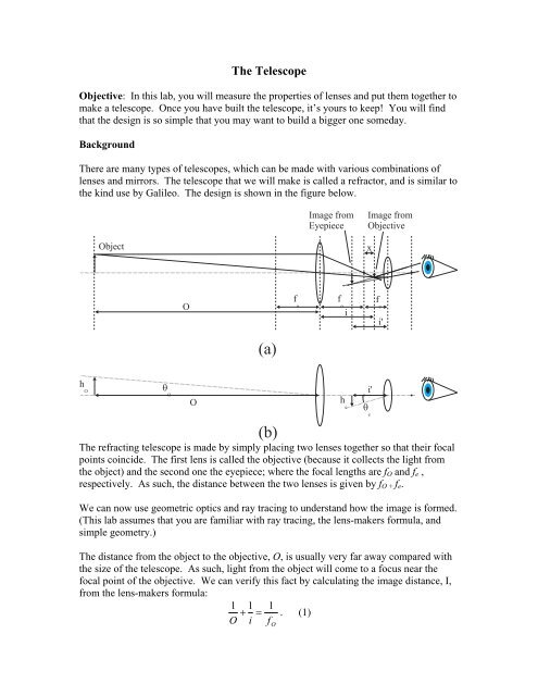
the kind use by Galileo. <strong>The</strong> design is shown in the figure below.<br />
<strong>The</strong> refracting telescope is made by simply placing two lenses together so that their focal<br />
points coincide. <strong>The</strong> first lens is called the objective (because it collects the light from<br />
the object) and the second one the eyepiece; where the focal lengths are f O and f e ,<br />
respectively. As such, the distance between the two lenses is given by f O + f e .<br />
We can now use geometric optics and ray tracing to understand how the image is formed.<br />
(This lab assumes that you are familiar with ray tracing, the lens-makers formula, and<br />
simple geometry.)<br />
<strong>The</strong> distance from the object to the objective, O, is usually very far away compared with<br />
the size of the telescope. As such, light from the object will come to a focus near the<br />
focal point of the objective. We can verify this fact by calculating the image distance, I,<br />
from the lens-makers formula:<br />
1 1 1<br />
+ = . (1)<br />
O i<br />
f O
Solving for the image distance, we get:<br />
2<br />
f<br />
O<br />
f<br />
O<br />
i = ≈ f<br />
O<br />
+ , (2)<br />
f<br />
O O<br />
1−<br />
O<br />
where we have made the approximation that the object distance is much larger then the<br />
focal length of the objective. <strong>The</strong> figure shows the image of the objective, which we can<br />
see is small and inverted. Clearly, when the object moves to infinity, the second term in<br />
the above equation vanishes and we find that the image approaches f O . <strong>The</strong> distance<br />
between the image and focal point is labeled x in the figure.<br />
<strong>The</strong> image from the objective now acts as the object for the eyepiece. In a since, we can<br />
think of the eyepiece as a magnifying lens that is used to look at the image produced by<br />
the objective. Note that the image produced by the objective is a real image since light<br />
actually focuses to a point. Now, we use the lens-makers formula to get the image<br />
distance from the eyepiece, i’,<br />
1 1 1<br />
+<br />
i'<br />
f<br />
= , (3)<br />
2<br />
e<br />
f<br />
e<br />
f<br />
e<br />
−<br />
O<br />
2<br />
fe<br />
where we have used the fact that the image from the objective is at a distance fe<br />
−<br />
O<br />
from the eyepiece (see the figure). Solving for i’, we get,<br />
2<br />
f f<br />
i ' = e<br />
e<br />
≈ − ⋅O<br />
1 f<br />
, (4)<br />
1−<br />
2<br />
O<br />
f<br />
O<br />
f<br />
O<br />
1−<br />
⋅<br />
f<br />
e<br />
O<br />
where we have again used the approximation that O>>f O . Note that from ray tracing, we<br />
find that at the eyepiece, the rays appear to be originating from i’, but there is no real<br />
light focused at that point. This is an example of a virtual image, therefore the negative<br />
sign for i’.<br />
<strong>The</strong> calculations above provide all of the information that we need to calculate the<br />
magnification. <strong>The</strong> magnification is defined as the angle subtended of the object as<br />
viewed through the telescope, θ e , divided by the angle subtended by the object as viewed<br />
with the naked eye, θ O . Part b of the figure shows these two angles. For small angles,<br />
tanθ =θ, so we have:<br />
h<br />
θ<br />
O<br />
= (5)<br />
O<br />
and<br />
f<br />
e<br />
hO<br />
hi<br />
f<br />
O<br />
f<br />
O<br />
h0<br />
θ<br />
e<br />
= = = ⋅ , (6)<br />
2<br />
i'<br />
f<br />
e<br />
f<br />
e<br />
O<br />
⋅O<br />
2<br />
f<br />
O
where the second equal sign results from using Equation 4 in the denominator and the<br />
numerator results from simple trigonometry * (see the figure). <strong>The</strong> magnification is then<br />
given by the ratio of Equation 6 to Equation 5:<br />
θ<br />
e<br />
f<br />
O<br />
m = = . (7)<br />
θ f<br />
Procedure<br />
O<br />
You will be given two lenses. Fix the lens in place and move a laser beam transverse to<br />
the beam as shown in the figure below.<br />
e<br />
Watch the beam that is transmitted by the lens on a screen. If the screen as at the focal<br />
point, the point on the screen will not move as the laser is translated. Measure the focal<br />
length of both lenses in this way.<br />
Using the focal lengths that your measured, mount the lenses confocally. When you<br />
launch light into the pair of lenses and shown in the figure below, and move the laser<br />
between two positions, the rays exiting should be parallel. This can be tested by<br />
measuring the positions of the two spots for the two rays just after the confocal pair and<br />
then on the other side of the room. If the lenses are confocal, the distance between the<br />
beams should be the same. Make small adjustments to the lenses until the exit beams are<br />
parallel and measure the distance between the lenses. How does this compare with the<br />
sum of the focal lengths you measured?<br />
* If h is the height of the image from the objective lens, then using similar triangles, we have h/h O = i/O and<br />
h e /h =i’/(f e -x). Taking the product of these two equations, and assuming x small and i‘=f O (which is a good<br />
approximation for small x), we get h e /h O = (f O /O)(i‘/f e ). Using Equation 4 to eliminate i‘, we get h e /h O =<br />
f e /f O .
Next, use the tubes provided to mount the two lenses. Without looking through the<br />
telescope, adjust the distance between the lenses so that they are confocal. Now look at a<br />
distance object through the window at the end of the hall. Is it in focus? How much did<br />
you need to adjust the telescope to bring it in focus?<br />
Remove the objective; insert the aperture and objective together back into the telescope;<br />
and look at a distant object. Do you see anything differently? You may want to remove<br />
and add the aperture several times to see what differences you notice. (<strong>The</strong> simplest way<br />
is to leave the aperture out of the telescope and hold it up to the objective by hand so that<br />
you can remove it and add it quickly).<br />
Finally, while viewing the distant object with one eye through the telescope, look at it<br />
with the other eye without the telescope simultaneously. From this estimate the<br />
magnification. How does this magnification compare with what you get from Equation<br />
(7).<br />
Take your telescope home and take a look at the moon and the stars…