Safety Precaution Sheet To be read carefully before use - Logitech Ltd
Safety Precaution Sheet To be read carefully before use - Logitech Ltd
Safety Precaution Sheet To be read carefully before use - Logitech Ltd
You also want an ePaper? Increase the reach of your titles
YUMPU automatically turns print PDFs into web optimized ePapers that Google loves.
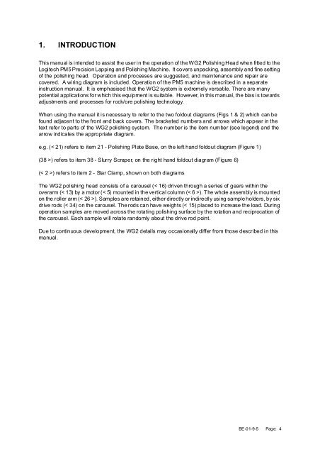
1. INTRODUCTION<br />
This manual is intended to assist the <strong>use</strong>r in the operation of the WG2 Polishing Head when fitted to the<br />
<strong>Logitech</strong> PM5 Precision Lapping and Polishing Machine. It covers unpacking, assembly and fine setting<br />
of the polishing head. Operation and processes are suggested, and maintenance and repair are<br />
covered. A wiring diagram is included. Operation of the PM5 machine is descri<strong>be</strong>d in a separate<br />
instruction manual. It is emphasised that the WG2 system is extremely versatile. There are many<br />
potential applications for which this equipment is suitable. However, in this manual, the bias is towards<br />
adjustments and processes for rock/ore polishing technology.<br />
When using the manual it is necessary to refer to the two foldout diagrams (Figs 1 & 2) which can <strong>be</strong><br />
found adjacent to the front and back covers. The bracketed num<strong>be</strong>rs and arrows which appear in the<br />
text refer to parts of the WG2 polishing system. The num<strong>be</strong>r is the item num<strong>be</strong>r (see legend) and the<br />
arrow indicates the appropriate diagram.<br />
e.g. (< 21) refers to item 21 - Polishing Plate Base, on the left hand foldout diagram (Figure 1)<br />
(38 >) refers to item 38 - Slurry Scraper, on the right hand foldout diagram (Figure 6)<br />
(< 2 >) refers to item 2 - Star Clamp, shown on both diagrams<br />
The WG2 polishing head consists of a caro<strong>use</strong>l (< 16) driven through a series of gears within the<br />
overarm (< 13) by a motor (< 5) mounted in the vertical column (< 6 >). The whole assembly is mounted<br />
on the roller arm (< 26 >). Samples are retained, either directly or indirectly using sample holders, by six<br />
drive rods (< 34) on the caro<strong>use</strong>l. The rods can have weights (< 15) placed to increase the load. During<br />
operation samples are moved across the rotating polishing surface by the rotation and reciprocation of<br />
the caro<strong>use</strong>l. Each sample will rotate randomly about the drive rod point.<br />
Due to continuous development, the WG2 details may occasionally differ from those descri<strong>be</strong>d in this<br />
manual.<br />
BE-01-9-5 Page: 4


