Ready Welder II Operation Manual. - Pirate4x4.Com
Ready Welder II Operation Manual. - Pirate4x4.Com
Ready Welder II Operation Manual. - Pirate4x4.Com
You also want an ePaper? Increase the reach of your titles
YUMPU automatically turns print PDFs into web optimized ePapers that Google loves.
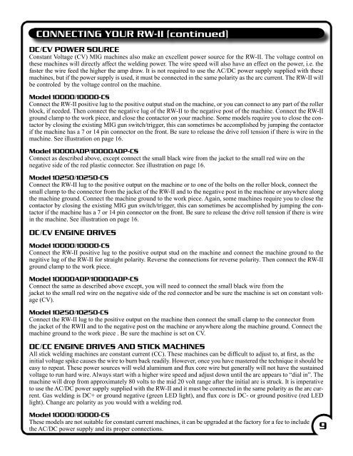
CONNECTING YOUR RW-<strong>II</strong> (continued)<br />
DC/CV POWER SOURCE<br />
Constant Voltage (CV) MIG machines also make an excellent power source for the RW-<strong>II</strong>. The voltage control on<br />
these machines will directly affect the welding power. The wire speed will also have an effect on the power, i.e. the<br />
faster the wire feed the higher the amp draw. It is not required to use the AC/DC power supply supplied with these<br />
machines, but if the power supply is used, it must be connected in the same polarity as the arc current. The RW-<strong>II</strong> will<br />
be controled by the voltage control on the machine.<br />
Model 10000/10000-CS<br />
Connect the RW-<strong>II</strong> positive lug to the positive output stud on the machine, or you can connect to any part of the roller<br />
block, if needed. Then connect the negative lug of the RW-<strong>II</strong> to the negative post of the machine. Connect the RW-<strong>II</strong><br />
ground clamp to the work piece, and close the contactor on your machine. Some models require you to close the contactor<br />
by closing the existing MIG gun switch/trigger, this can sometimes be accomplished by jumping the contactor<br />
if the machine has a 7 or 14 pin connector on the front. Be sure to release the drive roll tension if there is wire in the<br />
machine. See illustration on page 16.<br />
Model 10000ADP/10000ADP-CS<br />
Connect as described above, except connect the small black wire from the jacket to the small red wire on the<br />
negative side of the red plastic connector. See illustration on page 16.<br />
Model 10250/10250-CS<br />
Connect the RW-<strong>II</strong> lug to the positive output on the machine or to one of the bolts on the roller block, connect the<br />
small clamp to the connector from the jacket of the RW-<strong>II</strong> and to the negative post in the machine or anywhere along<br />
the machine ground. Connect the machine ground to the work piece. Again, some machines require you to close the<br />
contactor by closing the existing MIG gun switch/trigger, this can sometimes be accomplished by jumping the contactor<br />
if the machine has a 7 or 14 pin connector on the front. Be sure to release the drive roll tension if there is wire<br />
in the machine. See illustration on page 16.<br />
DC/CV ENGINE DRIVES<br />
Model 10000/10000-CS<br />
Connect the RW-<strong>II</strong> positive lug to the positive output stud on the machine and connect the machine ground to the<br />
negitive lug of the RW-<strong>II</strong> for straight polarity. Reverse the connections for reverse polarity. Then connect the RW-<strong>II</strong><br />
ground clamp to the work piece.<br />
Model 10000ADP/10000ADP-CS<br />
Connect the same as described above except, you will need to connect the small black wire from the<br />
jacket to the small red wire on the negative side of the red connector and be sure the machine is set on constant voltage<br />
(CV).<br />
Model 10250/10250-CS<br />
Connect the RW-<strong>II</strong> lug to the positive output on the machine then connect the small clamp to the connector from<br />
the jacket of the RW<strong>II</strong> and to the negative post on the machine or anywhere along the machine ground. Connect the<br />
machine ground to the work piece . Be sure the machine is set on CV.<br />
DC/CC ENGINE DRIVES AND STICK MACHINES<br />
All stick welding machines are constant current (CC). These machines can be difficult to adjust to, at first, as the<br />
initial voltage spike causes the wire to burn back readily. However, once you have mastered the technique it should be<br />
easy to repeat. These power sources will weld aluminum and flux core wire but generally will not have the sustained<br />
voltage to run hard wire. Always start with a higher wire speed and adjust down until the arc appears to “dial in”. The<br />
machine will drop from approximately 80 volts to the mid 20 volt range after the initial arc is struck. It is imperative<br />
to use the AC/DC power supply supplied with the RW-<strong>II</strong> and it must be connected in the same polarity as the arc current.<br />
Gas welding is DC+ or ground negative (green LED light), and flux core is DC- or ground positive (red LED<br />
light). Change arc polarity as you would with a welding rod.<br />
Model 10000/10000-CS<br />
These models are not suitable for constant current machines, it can be upgraded at the factory for a fee to include<br />
the AC/DC power supply and its proper connections.<br />
9


