Road Test: Strong Technobeam, page 40 - PLSN.com
Road Test: Strong Technobeam, page 40 - PLSN.com
Road Test: Strong Technobeam, page 40 - PLSN.com

Create successful ePaper yourself
Turn your PDF publications into a flip-book with our unique Google optimized e-Paper software.
PRODUCT SPOTLIGHT<br />
PROJECTION LIGHTS & STAGING NEWS<br />
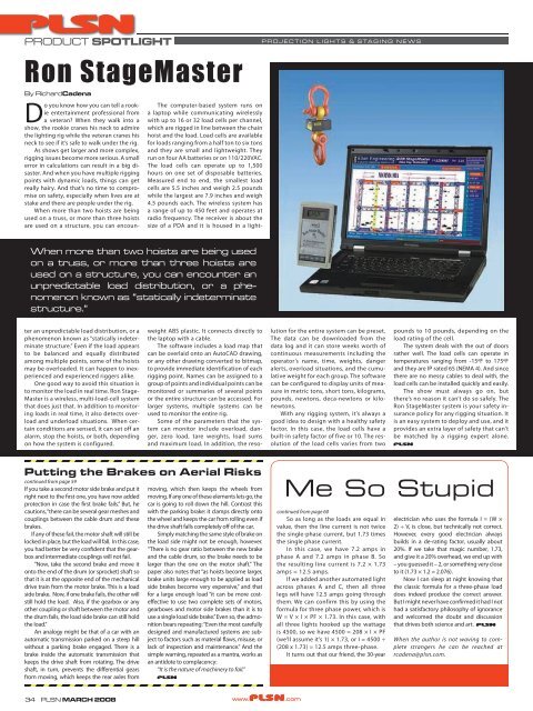
Ron StageMaster<br />
By RichardCadena<br />
Do you know how you can tell a rookie<br />
entertainment professional from<br />
a veteran? When they walk into a<br />
show, the rookie cranes his neck to admire<br />
the lighting rig while the veteran cranes his<br />
neck to see if it’s safe to walk under the rig.<br />
As shows get larger and more <strong>com</strong>plex,<br />
rigging issues be<strong>com</strong>e more serious. A small<br />
error in calculations can result in a big disaster.<br />
And when you have multiple rigging<br />
points with dynamic loads, things can get<br />
really hairy. And that’s no time to <strong>com</strong>promise<br />
on safety, especially when lives are at<br />
stake and there are people under the rig.<br />
When more than two hoists are being<br />
used on a truss, or more than three hoists<br />
are used on a structure, you can encoun-<br />
The <strong>com</strong>puter-based system runs on<br />
a laptop while <strong>com</strong>municating wirelessly<br />
with up to 16 or 32 load cells per channel,<br />
which are rigged in line between the chain<br />
hoist and the load. Load cells are available<br />
for loads ranging from a half ton to six tons<br />
and they are small and lightweight. They<br />
run on four AA batteries or on 110/220VAC.<br />
The load cells can operate up to 1,500<br />
hours on one set of disposable batteries.<br />
Measured end to end, the smallest load<br />
cells are 5.5 inches and weigh 2.5 pounds<br />
while the largest are 7.9 inches and weigh<br />
4.5 pounds each. The wireless system has<br />
a range of up to 450 feet and operates at<br />
radio frequency. The receiver is about the<br />
size of a PDA and it is housed in a light-<br />
When more than two hoists are being used<br />
on a truss, or more than three hoists are<br />
used on a structure, you can encounter an<br />
unpredictable load distribution, or a phenomenon<br />
known as “statically indeterminate<br />
structure.”<br />
ter an unpredictable load distribution, or a<br />
phenomenon known as “statically indeterminate<br />
structure.” Even if the load appears<br />
to be balanced and equally distributed<br />
among multiple points, some of the hoists<br />
may be overloaded. It can happen to inexperienced<br />
and experienced riggers alike.<br />
One good way to avoid this situation is<br />
to monitor the load in real time. Ron Stage-<br />
Master is a wireless, multi-load-cell system<br />
that does just that. In addition to monitoring<br />
loads in real time, it also detects overload<br />
and underload situations. When certain<br />
conditions are sensed, it can set off an<br />
alarm, stop the hoists, or both, depending<br />
on how the system is configured.<br />
weight ABS plastic. It connects directly to<br />
the laptop with a cable.<br />
The software includes a load map that<br />
can be overlaid onto an AutoCAD drawing,<br />
or any other drawing converted to bitmap,<br />
to provide immediate identification of each<br />
rigging point. Names can be assigned to a<br />
group of points and individual points can be<br />
monitored or summaries of several points<br />
or the entire structure can be accessed. For<br />
larger systems, multiple systems can be<br />
used to monitor the entire rig.<br />
Some of the parameters that the system<br />
can monitor include overload, danger,<br />
zero load, tare weights, load sums<br />
and maximum load. In addition, the resolution<br />
for the entire system can be preset.<br />
The data can be downloaded from the<br />
data log and it can store weeks worth of<br />
continuous measurements including the<br />
operator’s name, time, weights, danger<br />
alerts, overload situations, and the cumulative<br />
weight for each group. The software<br />
can be configured to display units of measure<br />
in metric tons, short tons, kilograms,<br />
pounds, newtons, deca-newtons or kilonewtons.<br />
With any rigging system, it’s always a<br />
good idea to design with a healthy safety<br />
factor. In this case, the load cells have a<br />
built-in safety factor of five or 10. The resolution<br />
of the load cells varies from two<br />
pounds to 10 pounds, depending on the<br />
load rating of the cell.<br />
The system deals with the out of doors<br />
rather well. The load cells can operate in<br />
temperatures ranging from -15ºF to 175ºF<br />
and they are IP rated 65 (NEMA 4). And since<br />
there are no messy cables to deal with, the<br />
load cells can be installed quickly and easily.<br />
The show must always go on, but<br />
there’s no reason it can’t do so safely. The<br />
Ron StageMaster system is your safety insurance<br />
policy for any rigging situation. It<br />
is an easy system to deploy and use, and it<br />
provides an extra layer of safety that can’t<br />
be matched by a rigging expert alone.<br />
Putting the Brakes on Aerial Risks<br />
continued from <strong>page</strong> 59<br />
If you take a second motor side brake and put it<br />
right next to the first one, you have now added<br />
protection in case the first brake fails.” But, he<br />
cautions, “there can be several gear meshes and<br />
couplings between the cable drum and these<br />
brakes.<br />
If any of these fail, the motor shaft will still be<br />
locked in place, but the load will fall. In this case,<br />
you had better be very confident that the gearbox<br />
and intermediate couplings will not fail.<br />
“Now, take the second brake and move it<br />
onto the end of the drum (or sprocket) shaft so<br />
that it is at the opposite end of the mechanical<br />
drive train from the motor brake. This is a load<br />
side brake. Now, if one brake fails, the other will<br />
still hold the load. Also, if the gearbox or any<br />
other coupling or shaft between the motor and<br />
the drum fails, the load side brake can still hold<br />
the load.”<br />
An analogy might be that of a car with an<br />
automatic transmission parked on a steep hill<br />
without a parking brake engaged. There is a<br />
brake inside the automatic transmission that<br />
keeps the drive shaft from rotating. The drive<br />
shaft, in turn, prevents the differential gears<br />
from moving, which keeps the rear axles from<br />
moving, which then keeps the wheels from<br />
moving. If any one of these elements lets go, the<br />
car is going to roll down the hill. Contrast this<br />
with the parking brake: it clamps directly onto<br />
the wheel and keeps the car from rolling even if<br />
the drive shaft falls <strong>com</strong>pletely off of the car.<br />
Simply matching the same style of brake on<br />
the load side might not be enough, however.<br />
“There is no gear ratio between the new brake<br />
and the cable drum, so the brake needs to be<br />
larger than the one on the motor shaft.” The<br />
paper also notes that “as hoists be<strong>com</strong>e larger,<br />
brake units large enough to be applied as load<br />
side brakes be<strong>com</strong>e very expensive,” and that<br />
for a large enough load “it can be more costeffective<br />
to use two <strong>com</strong>plete sets of motors,<br />
gearboxes and motor side brakes than it is to<br />
use a single load side brake.” Even so, the admonition<br />
bears repeating: “Even the most carefully<br />
designed and manufactured systems are subject<br />
to factors such as material flaws, misuse, or<br />
lack of inspection and maintenance.” And the<br />
simple warning, repeated as a mantra, works as<br />
an antidote to <strong>com</strong>placency:<br />
“It is the nature of machinery to fail.”<br />
Me So Stupid<br />
continued from <strong>page</strong> 60<br />
So as long as the loads are equal in<br />
value, then the line current is not twice<br />
the single-phase current, but 1.73 times<br />
the single phase current.<br />
In this case, we have 7.2 amps in<br />
phase A and 7.2 amps in phase B. So<br />
the resulting line current is 7.2 × 1.73<br />
amps = 12.5 amps.<br />
If we added another automated light<br />
across phases A and C, then all three<br />
legs will have 12.5 amps going through<br />
them. We can confirm this by using the<br />
formula for three phase power, which is<br />
W = V × I × PF × 1.73. In this case, with<br />
all three lights hooked up the wattage<br />
is 4500, so we have 4500 = 208 × I × PF<br />
(we’ll assume it’s 1) × 1.73, or I = 4500 ÷<br />
(208 x 1.73) = 12.5 amps three-phase.<br />
It turns out that our friend, the 30-year<br />
electrician who uses the formula I = (W ×<br />
2) ÷ V, is close, but technically not correct.<br />
However, every good electrician always<br />
builds in a de-rating factor, usually about<br />
20%. If we take that magic number, 1.73,<br />
and give it a 20% overhead, we end up with<br />
– you guessed it – 2, or something very close<br />
to it (1.73 × 1.2 = 2.076).<br />
Now I can sleep at night knowing that<br />
the classic formula for a three-phase load<br />
does indeed produce the correct answer.<br />
But I might never have confirmed it had I not<br />
had a satisfactory philosophy of ignorance<br />
and wel<strong>com</strong>ed the doubt and discussion<br />
that drives both science and art.<br />
When the author is not waving to <strong>com</strong>plete<br />
strangers he can be reached at<br />
rcadena@plsn.<strong>com</strong>.<br />
34<br />
<strong>PLSN</strong> MARCH 2008