- Page 1 and 2: Tibbo Ethernet-to-Serial Devices: H
- Page 3 and 4: Contents II Mechanical dimensions .
- Page 5 and 6: Contents IV Start On Any Character
- Page 7 and 8: Contents VI More info on the Tx buf
- Page 9 and 10: Contents VIII Stop character (.....
- Page 11 and 12: Hardware Manuals 10 Item EM100 EM12
- Page 13 and 14: Hardware Manuals 12 Ethernet port o
- Page 15 and 16: Hardware Manuals 14 The firmware of
- Page 17 and 18: Hardware Manuals 16 Mechanical 2.1.
- Page 19 and 20: Hardware Manuals 18 that will be de
- Page 21 and 22: Hardware Manuals 20 Logical signals
- Page 23 and 24: Hardware Manuals 22 Mechanical 2.1.
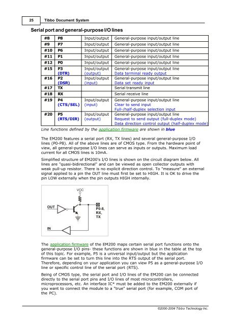
- Page 25: Hardware Manuals 24 I/O pin 2.1.4.1
- Page 29 and 30: Hardware Manuals 28 Mechanical 2.1.
- Page 31 and 32: Hardware Manuals 30 I/O pin 2.1.5.1
- Page 33 and 34: Hardware Manuals 32 ICs** invert th
- Page 35 and 36: Hardware Manuals 34 LEDs have the f
- Page 37 and 38: Hardware Manuals 36 Specifications
- Page 39 and 40: Hardware Manuals 38 Ethernet 2.2.1.
- Page 41 and 42: Hardware Manuals 40 Ethernet 2.2.2.
- Page 43 and 44: Hardware Manuals 42 EM202-EV Ethern
- Page 45 and 46: Hardware Manuals 44 #1 #2 RX (inpu
- Page 47 and 48: Hardware Manuals 46 L Aver. 52.6 Bo
- Page 49 and 50: Hardware Manuals 48 "service" firmw
- Page 51 and 52: Hardware Manuals 50 DS100R DS100B R
- Page 53 and 54: Hardware Manuals 52 DS100R-02 canno
- Page 55 and 56: Hardware Manuals 54 Ethernet port p
- Page 57 and 58: Hardware Manuals 56 Specifications
- Page 59 and 60: Hardware Manuals 58 · WAS-P0005(B)
- Page 61 and 62: Hardware Manuals 60 WAS-1498 "cross
- Page 63 and 64: Hardware Manuals 62 Wall installati
- Page 65 and 66: Hardware Manuals 64 Latch the DS100
- Page 67 and 68: Firmware Manuals 66 Slow-blinking G
- Page 69 and 70: Firmware Manuals 68 First-generatio
- Page 71 and 72: Firmware Manuals 70 closed). Means
- Page 73 and 74: Firmware Manuals 72 Exactly when th
- Page 75 and 76: Firmware Manuals 74 DHCP attempts t
- Page 77 and 78:
Firmware Manuals 76 full- and half-
- Page 79 and 80:
Firmware Manuals 78 Serial data blo
- Page 81 and 82:
Firmware Manuals 80 There are two m
- Page 83 and 84:
Firmware Manuals 82 over the networ
- Page 85 and 86:
Firmware Manuals 84 All command-pha
- Page 87 and 88:
Firmware Manuals 86 discussed: seri
- Page 89 and 90:
Firmware Manuals 88 Quick initializ
- Page 91 and 92:
Firmware Manuals 90 R.C. A C R D F
- Page 93 and 94:
Firmware Manuals 92 phase (Denied (
- Page 95 and 96:
Firmware Manuals 94 Compatibility w
- Page 97 and 98:
Firmware Manuals 96 * Without prior
- Page 99 and 100:
Firmware Manuals 98 Echo command is
- Page 101 and 102:
Firmware Manuals 100 capacity is 51
- Page 103 and 104:
Firmware Manuals 102 command body i
- Page 105 and 106:
Firmware Manuals 104 Possible repli
- Page 107 and 108:
Firmware Manuals 106 · Encapsulati
- Page 109 and 110:
Firmware Manuals 108 Relevance cond
- Page 111 and 112:
Firmware Manuals 110 Echo (X) comma
- Page 113 and 114:
Firmware Manuals 112 Transport Prot
- Page 115 and 116:
Firmware Manuals 114 Overriding par
- Page 117 and 118:
Firmware Manuals 116 2 (client) Onl
- Page 119 and 120:
Firmware Manuals 118 Details Destin
- Page 121 and 122:
Firmware Manuals 120 Change takes e
- Page 123 and 124:
Firmware Manuals 122 Password (PW)
- Page 125 and 126:
Firmware Manuals 124 Half-duplex op
- Page 127 and 128:
Firmware Manuals 126 Change takes e
- Page 129 and 130:
Firmware Manuals 128 Relevance cond
- Page 131 and 132:
Firmware Manuals 130 side) Paramete
- Page 133 and 134:
Firmware Manuals 132 Bit position E
- Page 135 and 136:
Firmware Manuals 134 related to rou
- Page 137 and 138:
Firmware Manuals 136 This setting e
- Page 139 and 140:
Firmware Manuals 138 See also: Seri
- Page 141 and 142:
Firmware Manuals 140 Parameter/ ins
- Page 143 and 144:
Firmware Manuals 142 Details Bits P
- Page 145 and 146:
Firmware Manuals 144 pins to implem
- Page 147 and 148:
Firmware Manuals 146 Error (C) repl
- Page 149 and 150:
Firmware Manuals 148 Destination IP
- Page 151 and 152:
Firmware Manuals 150 address (DI) s
- Page 153 and 154:
Firmware Manuals 152 · New: accept
- Page 155 and 156:
Firmware Manuals 154 At this point
- Page 157 and 158:
Firmware Manuals 156 NetLoader are
- Page 159 and 160:
Firmware Manuals 158 B- '+' in this
- Page 161 and 162:
Firmware Manuals 160 It is importan
- Page 163 and 164:
Firmware Manuals 162 of the applica
- Page 165 and 166:
Software Manuals 164 DS Manager Dev
- Page 167 and 168:
Software Manuals 166 Normal state.
- Page 169 and 170:
Software Manuals 168 Device Servers
- Page 171 and 172:
Software Manuals 170 Broadcast acce
- Page 173 and 174:
Software Manuals 172 after the firs
- Page 175 and 176:
Software Manuals 174 consists of se
- Page 177 and 178:
Software Manuals 176 already has a
- Page 179 and 180:
Software Manuals 178 · Incorrect p
- Page 181 and 182:
Software Manuals 180 Functions 4.1.
- Page 183 and 184:
Software Manuals 182 possible if a
- Page 185 and 186:
Software Manuals 184 Routing status
- Page 187 and 188:
Software Manuals 186 Editing the ad
- Page 189 and 190:
Software Manuals 188 IP-address not
- Page 191 and 192:
Software Manuals 190 Routing buffer
- Page 193 and 194:
Software Manuals 192 Broadcast acce
- Page 195 and 196:
Software Manuals 194 DS lost (after
- Page 197 and 198:
Software Manuals 196 Here is why th
- Page 199 and 200:
Software Manuals 198 The DS Manager
- Page 201 and 202:
Software Manuals 200 Invalid firmwa
- Page 203 and 204:
Software Manuals 202 No response fr
- Page 205 and 206:
Software Manuals 204 Potential DHCP
- Page 207 and 208:
Software Manuals 206 the upgrade Ma
- Page 209 and 210:
Software Manuals 208 available Devi
- Page 211 and 212:
Software Manuals 210 · Outbound pa
- Page 213 and 214:
Software Manuals 212 application so
- Page 215 and 216:
Software Manuals 214 · In phase A
- Page 217 and 218:
Software Manuals 216 packet is rece
- Page 219 and 220:
Software Manuals 218 Out-of-band co
- Page 221 and 222:
Software Manuals 220 --- --- connec
- Page 223 and 224:
Software Manuals 222 · The change
- Page 225 and 226:
Software Manuals 224 Disabled (with
- Page 227 and 228:
Software Manuals 226 Destination mo
- Page 229 and 230:
Software Manuals 228 contains a "no
- Page 231 and 232:
Software Manuals 230 The prefix str
- Page 233 and 234:
Software Manuals 232 The simplest w
- Page 235 and 236:
Software Manuals 234 this way). For
- Page 237 and 238:
Software Manuals 236 (i.e. not in u
- Page 239 and 240:
Software Manuals 238 icon in the sy
- Page 241 and 242:
Software Manuals 240 Connection Wiz
- Page 243 and 244:
Software Manuals 242 · Choosing se
- Page 245 and 246:
Software Manuals 244 · There is an
- Page 247 and 248:
Software Manuals 246 Initiator of t
- Page 249 and 250:
Software Manuals 248 symmetrical. F
- Page 251 and 252:
Software Manuals 250 The situation
- Page 253 and 254:
Software Manuals 252 The VSP-to-DS
- Page 255 and 256:
Software Manuals 254 The screen wit
- Page 257 and 258:
Software Manuals 256 When working o
- Page 259 and 260:
Software Manuals 258 programming th
- Page 261 and 262:
Software Manuals 260 data may alrea
- Page 263 and 264:
Software Manuals 262 Which side can
- Page 265 and 266:
Software Manuals 264 setup the appl
- Page 267 and 268:
Software Manuals 266 There are two
- Page 269 and 270:
Software Manuals 268 IP-address. DS
- Page 271 and 272:
Software Manuals 270 access method-
- Page 273 and 274:
Software Manuals 272 What if the DS
- Page 275 and 276:
Software Manuals 274 will program t
- Page 277 and 278:
Software Manuals 276 The situation
- Page 279 and 280:
Software Manuals 278 When this feat
- Page 281 and 282:
Software Manuals 280 Parameters for
- Page 283 and 284:
Software Manuals 282 the DS may be
- Page 285 and 286:
Software Manuals 284 Reviewing 4.1.
- Page 287 and 288:
Software Manuals 286 MAC-->IP mappi
- Page 289 and 290:
Software Manuals 288 Invalid IP-add
- Page 291 and 292:
Software Manuals 290 VSP transparen
- Page 293 and 294:
Software Manuals 292 · libgcc_s.so
- Page 295 and 296:
Software Manuals 294 [<
- Page 297 and 298:
Software Manuals 296 timeout="2" on
- Page 299 and 300:
Software Manuals 298 VSPdaemon even
- Page 301 and 302:
Software Manuals 300 Host parameter
- Page 303 and 304:
Software Manuals 302 UDP, on the co
- Page 305 and 306:
Software Manuals 304 mode outgoing
- Page 307 and 308:
Software Manuals 306 Password for o
- Page 309 and 310:
Software Manuals 308 potentially ch
- Page 311 and 312:
Software Manuals 310 packet size of
- Page 313 and 314:
Software Manuals 312 Type parameter
- Page 315 and 316:
Application Notes 314 The first lin
- Page 317 and 318:
Application Notes 316 default selec
- Page 319 and 320:
Application Notes 318 network-enabl
- Page 321 and 322:
Application Notes 320 also importan
- Page 323 and 324:
Application Notes 322 In some cases
- Page 325 and 326:
Application Notes 324 192.168.100.9
- Page 327 and 328:
Application Notes 326 · Transport
- Page 329 and 330:
Application Notes 328 commands are
- Page 331 and 332:
Application Notes 330 message: This
- Page 333 and 334:
Application Notes 332 opened. To do
- Page 335 and 336:
Update history 334 Update history T