Hybrid IC IGBT Gate Driver VLA504 - Powerex
Hybrid IC IGBT Gate Driver VLA504 - Powerex
Hybrid IC IGBT Gate Driver VLA504 - Powerex

You also want an ePaper? Increase the reach of your titles
YUMPU automatically turns print PDFs into web optimized ePapers that Google loves.
<strong>Powerex</strong>, Inc., 173 Pavilion Lane, Youngwood, Pennsylvania 15697-1800 (724) 925-7272<br />
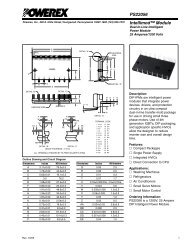
<strong>VLA504</strong><br />
<strong>Hybrid</strong> <strong>IC</strong> <strong>IGBT</strong> <strong>Gate</strong> <strong>Driver</strong><br />
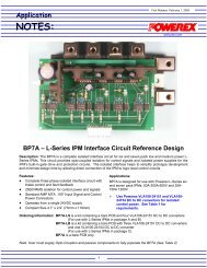
Application Circuit<br />
<strong>VLA504</strong><br />
+5V<br />
14 13 10 9 8 6 5 4 3 2 1<br />
+<br />
D1<br />
CONTROL<br />
FAULT<br />
B1<br />
PS2501<br />
+ C1<br />
+<br />
C2<br />
C trip<br />
30V<br />
+<br />
V CC<br />
4.7k<br />
R G<br />
18V<br />
18V<br />
G<br />
<strong>IGBT</strong><br />
MODULE<br />
C<br />
+<br />
V EE<br />
E<br />
E<br />
Component Selection:<br />
Design Description<br />
V CC , V EE +15V/-10V Typical, See data sheet for usable limits<br />
R G<br />
Adjust for application requirements. See <strong>IGBT</strong> module application notes<br />
for recommendations and power rating<br />
C1, C2 10µF-100µF 25V low impedance electrolytic<br />
D1<br />
Ultra fast recovery t rr V ces (<strong>IGBT</strong>)<br />
C trip 0-200pF adjusts desaturation trip time (t trip )<br />
B1<br />
CMOS Buffer 74HC04 or similar – Must actively pull high to maintain noise immunity<br />
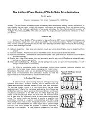
Single Supply Operation<br />
Notes:<br />
(1) Power supply decoupling capacitors C1 and C2 should be connected as close as possible to the pins of the<br />
gate driver and must be sized to have appropriate ESR and ripple current capability for the <strong>IGBT</strong> being driven.<br />
(2) C trip should be connected as close as possible to the pins of the gate driver to avoid noise pick-up.<br />
(3) All zener diodes 1W, all resistors 0.25W unless otherwise noted.<br />
<strong>VLA504</strong><br />
+5V<br />
14 13 10 9 8 6 5 4 3 2 1<br />
+<br />
D1<br />
CONTROL<br />
FAULT<br />
B1<br />
PS2501<br />
+ C1<br />
+<br />
C2<br />
C trip<br />
30V<br />
+<br />
2.7k<br />
4.7k<br />
R G<br />
18V<br />
18V<br />
G<br />
<strong>IGBT</strong><br />
MODULE<br />
C<br />
V CC<br />
8.2V<br />
E<br />
E<br />
Rev. 2/06<br />
3