Hybrid IC IGBT Gate Driver VLA504 - Powerex
Hybrid IC IGBT Gate Driver VLA504 - Powerex
Hybrid IC IGBT Gate Driver VLA504 - Powerex

You also want an ePaper? Increase the reach of your titles
YUMPU automatically turns print PDFs into web optimized ePapers that Google loves.
<strong>Powerex</strong>, Inc., 173 Pavilion Lane, Youngwood, Pennsylvania 15697-1800 (724) 925-7272<br />
<strong>VLA504</strong><br />
<strong>Hybrid</strong> <strong>IC</strong> <strong>IGBT</strong> <strong>Gate</strong> <strong>Driver</strong><br />
General Description<br />
The <strong>VLA504</strong> is a hybrid integrated circuit designed<br />
to provide gate drive for high power <strong>IGBT</strong> modules.<br />
This circuit has been optimized for use with <strong>Powerex</strong><br />
NF-Series and A-Series <strong>IGBT</strong> modules. However, the<br />
output characteristics are compatible with most MOS<br />
gated power devices. The <strong>VLA504</strong> features a compact<br />
single-in-line package design. The upright mounting<br />
minimizes required printed circuit board space to allow<br />
efficient and flexible layout. The <strong>VLA504</strong> converts logic<br />
level control signals into fully isolated +15V/-8V gate<br />
drive with up to 5A of peak drive current. Control signal<br />
isolation is provided by an integrated high speed optocoupler.<br />
Short circuit protection is provided by means of<br />
destauration detection.<br />
Short Circuit Protection<br />
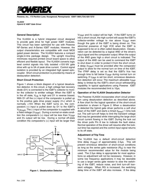
Figure 1 shows a block diagram of a typical desaturation<br />
detector. In this circuit, a high voltage fast recovery<br />
diode (D1) is connected to the <strong>IGBT</strong>’s collector to monitor<br />
the collector to emitter voltage. When the <strong>IGBT</strong> is<br />
in the off state, V CE is high and D1 is reverse biased.<br />
With D1 off the (+) input of the comparator is pulled up<br />
to the positive gate drive power supply (V+) which is<br />
normally +15V. When the <strong>IGBT</strong> turns on, the comparators<br />
(+) input is pulled down by D1 to the <strong>IGBT</strong>’s<br />
V CE(sat) . The (-) input of the comparator is supplied with<br />
a fixed voltage (V TRIP ). During a normal on-state condition<br />
the comparator’s (+) input will be less than V TRIP<br />
and it’s output will be low. During a normal off-state<br />
condition the comparator’s (+) input will be larger than<br />
INPUT<br />
DELAY<br />
t trip<br />
AND<br />
GATE<br />
DRIVE<br />
COMPARE<br />
SHUTDOWN<br />
R G<br />
V+<br />
D1<br />
V trip<br />
<strong>IGBT</strong><br />
MODULE<br />
Figure 1. Desaturation Detector<br />
+<br />
G<br />
E<br />
C<br />
E<br />
V TRIP and it’s output will be high. If the <strong>IGBT</strong> turns on<br />
into a short circuit, the high current will cause the <strong>IGBT</strong>’s<br />
collector-emitter voltage to rise above V TRIP even<br />
though the gate of the <strong>IGBT</strong> is being driven on. This<br />
abnormal presence of high VCE when the <strong>IGBT</strong> is<br />
supposed to be on is often called desaturation. Desaturation<br />
can be detected by a logical AND of the driver’s<br />
input signal and the comparator output. When the output<br />
of the AND goes high a short circuit is indicated. The<br />
output of the AND can be used to command the <strong>IGBT</strong><br />
to shut down in order to protect it from the short circuit.<br />
A delay (t TRIP ) must be provided after the comparator<br />
output to allow for the normal turn on time of the <strong>IGBT</strong>.<br />
The tTRIP delay is set so that the <strong>IGBT</strong>s Vce has<br />
enough time to fall below V TRIP during normal turn on<br />
switching. If t TRIP is set too short, erroneous desaturation<br />
detection will occur. The maximum allowable t TRIP<br />
delay is limited by the <strong>IGBT</strong>’s short circuit withstanding<br />
capability. In typical applications using <strong>Powerex</strong> <strong>IGBT</strong><br />
modules the recommended limit is 10µs.<br />
Operation of the <strong>VLA504</strong> Desaturation Detector<br />
The <strong>Powerex</strong> <strong>VLA504</strong> incorporates short circuit protection<br />
using desaturation detection as described above.<br />
A flow chart for the logical operation of the short-circuit<br />
protection is shown in Figure 2. When a desaturation<br />
is detected the hybrid gate driver performs a soft shut<br />
down of the <strong>IGBT</strong> and starts a timed (t timer ) 1.5ms lock<br />
out. The soft turn-off helps to limit the transient voltage<br />
that may be generated while interrupting the large short<br />
circuit current flowing in the <strong>IGBT</strong>. During the lock out<br />
the driver pulls Pin 8 low to indicate the fault status.<br />
Normal operation of the driver will resume after the lockout<br />
time has expired and the control input signal returns<br />
to its off state.<br />
Adjustment of Trip Time<br />
The <strong>VLA504</strong> has a default short-circuit detection<br />
time delay (t TRIP ) of approximately 2.5µs. This will<br />
prevent erroneous detection of short-circuit conditions<br />
as long as the series gate resistance (R G ) is near the<br />
minimum recommended value for the module being<br />
used. The 2.5µs delay is appropriate for most applications<br />
so adjustment will not be necessary. However, in<br />
some low frequency applications it may be desirable<br />
to use a larger series gate resistor to slow the switching<br />
of the <strong>IGBT</strong>, reduce noise, and limit turn-off transient<br />
voltages. When RG is increased, the switching<br />
delay time of the <strong>IGBT</strong> will also increase. If the delay<br />
Rev. 2/06<br />
5