Kenwood TK-7180 - KO4BB's Home Page
Kenwood TK-7180 - KO4BB's Home Page
Kenwood TK-7180 - KO4BB's Home Page

You also want an ePaper? Increase the reach of your titles
YUMPU automatically turns print PDFs into web optimized ePapers that Google loves.
CIRCUIT DESCRIPTION<br />
<strong>TK</strong>-<strong>7180</strong><br />
2-5. Squelch Circuit<br />
The output signal from IC172 enters FM IC again, then<br />
passed through a band-pass filter.<br />
The noise component output from IC172 is amplified by<br />
Q175 and rectified by D173 to produce a DC Voltage corresponding<br />
to the noise level. The DC voltage is sent to the<br />
analog port of the CPU (IC404).<br />
IC172 outputs a DC voltage (RSSI) corresponding to the<br />
input of the IF amplifier.<br />
3. Transmitter Circuit<br />
The transmitter circuit consists of the following circuits : 3-<br />
1 microphone circuit, 3-2 modulation level adjustment circuit,<br />
3-3 driver and final power amplifier circuit, and 3-4 automatic<br />
power control circuit.<br />
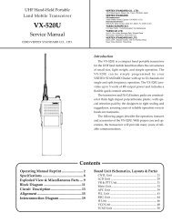
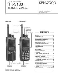
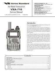
3-1. Microphone Circuit<br />
The audio signal from the microphone goes into TX-RX<br />
unit (X57-698) from the display unit (X54-348) and passes<br />
through the mute switch (Q416). The audio signal is amplified<br />
by the microphone amplifier (IC414) and is input into the<br />
TXIN terminal of the audio processor (IC415) after passing<br />
through the multiplexer (IC413).<br />
The input audio signal is output from the MOD terminal of<br />
the audio processor (IC415) and is amplified by the audio frequency<br />
amplifier (IC412) after passing through the electric<br />
volume (IC410).<br />
DISPLAY UNIT<br />
(X54-348)<br />
TX-RX UNIT (X57-698)<br />
3-2. Modulation Level Adjustment Circuit<br />
The audio signal amplified by the audio frequency amplifier<br />
(IC412) is added to the low speed data LSD passed<br />
through the low pass filter (IC409). The combined signals is<br />
supplied to the VCO (voltage controlled oscillator) and the<br />
VCXO (voltage controlled crystal oscillator) X301, respectively.<br />
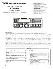
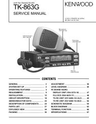
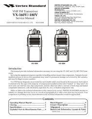
3-3. Driver and Final Power Amplifier Circuit<br />
The transmit signal obtained from the TX VCO buffer amplifier<br />
Q311, is amplified to approximately +17dBm by the<br />
driver amplifiers Q313, Q1 and Q2. This amplified signal is<br />
passed to the power amplifier module (power module) IC1,<br />
which consists of a MOS-FET amplifier and is capable of<br />
transmission output power.<br />
3-4. Automatic Power Control Circuit<br />
The automatic transmission power control (APC) circuit<br />
stabilizes the transmitter output power at a predetermined<br />
level by detecting the power module output with a diodes<br />
D6, D7 and D8. Diodes D6, D7 and D8 apply a voltage to DC<br />
amplifier IC72 (A/2). IC72 (B/2) compares the APC control<br />
voltage (PC) generated by microprocessor IC404 and DC amplifier<br />
IC71 (A/2, B/2) with the detection output voltage<br />
from IC72 (A/2) to control the Vgg pin of IC1, and stabilizes<br />
transmission output.<br />
The APC circuit is configured to protect over-current of the<br />
power module due to fluctuations of the load at the antenna<br />
end and to stabilize transmission output at voltage and temperature<br />
variations.<br />
Q416<br />
IC414<br />
IC413<br />
IC415<br />
IC410<br />
IC412<br />
J901<br />
Mojular<br />
jack<br />
MIC<br />
SW<br />
SW<br />
D-SUB<br />
MI2<br />
AMP<br />
Q417<br />
Multiplexer<br />
TXIN<br />
D-SUB<br />
DI<br />
LSDO<br />
AQUA-L<br />
MOD<br />
IC409<br />
LPF<br />
DAC<br />
AMP<br />
IC408<br />
DC<br />
AMP<br />
MOD<br />
(for VCO)<br />
MB<br />
(for VCXO)<br />
Fig. 2<br />
Microphone and modultion level adjustment circuit<br />
Q307<br />
Q311<br />
Buff<br />
AMP<br />
Q313<br />
Drive<br />
AMP<br />
Q1<br />
Drive<br />
AMP<br />
Q2<br />
Drive<br />
AMP<br />
IC1<br />
Final<br />
AMP<br />
D2~D4<br />
ANT<br />
MOD<br />
TX VCO<br />
SW<br />
Gate<br />
bias<br />
D6<br />
DET<br />
D7<br />
DET<br />
D8<br />
DET<br />
MB<br />
VCXO<br />
16.8MHz<br />
PC<br />
MP<br />
DC<br />
AMP<br />
DC<br />
AMP<br />
X301<br />
IC71<br />
IC72<br />
Fig. 3<br />
Drive and Final power amplifier and automatic power control circuit<br />
17