Kenwood TK-7180 - KO4BB's Home Page
Kenwood TK-7180 - KO4BB's Home Page
Kenwood TK-7180 - KO4BB's Home Page

You also want an ePaper? Increase the reach of your titles
YUMPU automatically turns print PDFs into web optimized ePapers that Google loves.
CIRCUIT DESCRIPTION<br />
<strong>TK</strong>-<strong>7180</strong><br />
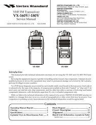
6. Power Supply Circuit<br />
The block diagram of the power supply circuit is shown in<br />
Figure 6.<br />
Power is always supplied from +B to the circuit (5M, +B)<br />
that is always started and the circuits (SB, 8C, 5E, 8T, 8R, 5C,<br />
5R) controlled by the CPU (IC404). When +B is supplied to<br />
the transceiver, Q801, D805 and IC805, regulate the voltage<br />
(5M) which is supplied to the circuit around the CPU. The<br />
CPU starts.<br />
When the CPU detects that the +B voltage is higher than<br />
the voltage prescribed by IC802, the transceiver power (SB)<br />
is turned ON by controlling the SBC signal (Low: transceiver<br />
power OFF, High: transceiver power ON).<br />
The CPU controls the TXC signal (Low: Transmission system<br />
power OFF, High: Transmission system power ON) during<br />
transmission to supply power (8T) to the transmission circuit.<br />
The CPU controls the RXC signal (Low: Reception system<br />
power OFF, High: Reception system power ON) during<br />
reception to supply power (8R, 5R) to the reception circuit.<br />
When the CPU detects the PSW (Power Switch) signal,<br />
IGN (Ignition Sense) signal or INT signal, it controls the SBC<br />
signal and turns the transceiver power (SB) OFF.<br />
If +B is not provided to the transceiver, power is supplied<br />
to only the RTC IC (IC402) through the secondary battery connected<br />
with CN401 to back up the clock.<br />
7. Display Circuit<br />
The display unit consists of the Panel CPU (IC902), the<br />
LCD driver (IC903), the TX/BUSY LED, the KEY detection, the<br />
Backlight and the Microphone jack circuits.<br />
The Panel CPU is a 16-bit microcomputer that contains a<br />
64k-byte Mask ROM and a 2k-byte RAM.<br />
The Panel CPU performs serial communication with the<br />
Main CPU (IC404) on the TX-RX unit (B/3) and the Panel CPU<br />
detects keys and sends data communication contents<br />
through the MIC Jack to the Main CPU. The Panel CPU receives<br />
commands from the Main CPU and controls the display<br />
system.<br />
The LCD operates with 1/9 duty under the LCD driver<br />
(IC903) control. The LCD and KEY Backlights are controlled<br />
by Q909. The display brightness of the LCD Backlight can be<br />
changed.<br />
Q910<br />
8C<br />
PSW<br />
SB<br />
RST2<br />
SHIFT<br />
PSENS<br />
SPO<br />
GND<br />
IC901<br />
AVR<br />
POWER<br />
SW<br />
TX/Busy<br />
LED<br />
RXD, TXD<br />
RED<br />
GRN<br />
Fig. 7<br />
Mask<br />
ROM<br />
IC902<br />
CPU<br />
MIC, ME<br />
BLCI<br />
DIMM<br />
Q909<br />
Display circuit<br />
IC903<br />
LCD<br />
driver<br />
LCD<br />
back<br />
light<br />
FKEY [1~10]<br />
SB<br />
HK, PTT, DM, BLC2<br />
LCD<br />
KEY<br />
back<br />
light<br />
Function<br />
KEY<br />
MIC<br />
jack<br />
SP<br />
Power supply : 10.8~15.7V +B<br />
F801<br />
5A<br />
Q810<br />
SW<br />
Q807<br />
SW<br />
IC803<br />
AVR<br />
IC807<br />
AVR<br />
SB<br />
8C<br />
5E<br />
Final amp.<br />
Audio amp, PA connector<br />
Panel block, D-sub block<br />
Internal option<br />
Panel block<br />
Internal option<br />
D804<br />
DET<br />
Q801,D805<br />
REG<br />
Q802<br />
SW<br />
Q811<br />
SW<br />
IC805<br />
AVR<br />
5M<br />
SBC<br />
CPU<br />
Flash memory<br />
EEPROM<br />
Ext-I/O<br />
Q803<br />
SW<br />
Q806<br />
SW<br />
Q804<br />
SW<br />
8T<br />
8R<br />
TX-drive<br />
APC block<br />
ANT SW<br />
TXC<br />
IF block<br />
IC802<br />
DET<br />
IC801<br />
DET<br />
CN401<br />
CPU #17<br />
: RST1<br />
RTC IC<br />
Q808<br />
SW<br />
IC804<br />
AVR<br />
Q805<br />
SW<br />
5C<br />
5R<br />
RXC<br />
VCXO, VCO, PLL IC<br />
IF detection IC<br />
DC/DC converter<br />
D/A converter<br />
MIC amp, AQUA<br />
AF block<br />
IF block<br />
CPU #24<br />
: INT<br />
Q809<br />
SW<br />
RXC<br />
Fig. 6<br />
Power supply circuit<br />
19