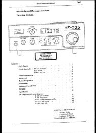
MFJ-8100K Manual
MFJ-8100K Manual
MFJ-8100K Manual

You also want an ePaper? Increase the reach of your titles
YUMPU automatically turns print PDFs into web optimized ePapers that Google loves.
Note: The L5 inductor for Band E is a wind-it-yourself "toroidal coil" (don't worry: it's<br />
easy!) which we'll make and install in Phase 5 so that it is not subjected to<br />
bumping and bending during other assembly.<br />
1-6. Install R4, 10K (brown-black-orange). Its position is between L1 and L2.<br />
1-7. Install C4, .1µF (body marking: 104Z), near L1.<br />
1-8. Install R13, 2.2K (red-red-red). (This is a current limiting resistor for the LED<br />
power indicator.)<br />
1-9. Install C3, 47pf (body marking: 47 or 470).<br />
1-10. Install C5, the miniature trimmer capacitor, making sure the to orient its body<br />
shape just like the circuit board outline. Before soldering , adjust the tuning<br />
screw so that its slot is pointed just like the outline on the board.<br />
We've accomplished something important; we got started, and we've made sure that this<br />
receiver will tune correctly.<br />
Construction Phase 2 (Steps 2-1 through 2-20)<br />
The parts in Phase 2 are the heart of your receiver; working together with the tuning<br />
circuit begun in Phase 1. Building this section is simply a matter of identifying and<br />
installing the parts correctly. This phase includes all three FET transistors and one<br />
electrolytic capacitor, all of which are to be installed in one correct way only. You really<br />
can't go wrong; simply position the transistors and electrolytic capacitors exactly as<br />
illustrated, right on the board.<br />
2-1. Install R5, 10K (brown-black-orange).<br />
2-2. Install C7, .01µF (body marking 103M).<br />
2-3. Install C18, 1µF electrolytic. Notice that the negative (-) side is clearly<br />
marked on the capacitor, and that the (+) position is marked on the PC board.<br />
2-4. Install R3, 10K (brown-black-orange).<br />
2-5. Install R6, 1K (brown-black-red).<br />
2-6. Install R17, 10 ohm (brown-black-black).<br />
2-7. Install C6, 33pF (body marking 33K).<br />
20