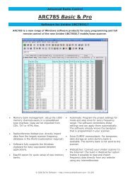
MFJ-8100K Manual
MFJ-8100K Manual
MFJ-8100K Manual

You also want an ePaper? Increase the reach of your titles
YUMPU automatically turns print PDFs into web optimized ePapers that Google loves.
Construction Phase 3 (Steps 3-1 through 3-20)<br />
The following group of parts form the audio amplifier circuit which boosts the signal<br />
from the FET transistors to useful listening volume.<br />
3-1a. Examine the 8-pin socket for the LM386 IC and notice the rectangular notch<br />
at one end. This notch should be oriented in exactly the same direction as<br />
imprinted on the board (toward C14). Press the socket pins into their 8 holes<br />
so that the socket rests flat on the board. You may wish to slightly bend two<br />
or more pins after insertion so that the socket won't slip out.<br />
3-1b. After making sure that all 8 pins are clearly visible on the bottom of the board,<br />
solder each connection carefully. Be sure not to let the solder tip touch two<br />
pins at the same time, which would cause unwanted "solder bridges".<br />
3-2a. In step 2-3 above, you installed the first of the 5 electrolytic capacitors used in<br />
the receiver. The remaining 4 are of this amplifier section. We'll install all of<br />
them now, so that the importance of correct (+) and (-) positioning stays fresh<br />
in mind.<br />
3-2b. Install C19, 470µF per 3-2a (above).<br />
3-3. Install C13, 100µF per 3-2a (above).<br />
3-4. Install C14, 10µF per 3-2a (above).<br />
3-5. Install C12, 22µF per 3-2a (above).<br />
3-6. Before proceeding, please double-check the polarity correctness for all 5<br />
electrolytic capacitor!<br />
3-7. Install R11, 22 ohms (red-red-black).<br />
3-8. Install R12, 15 ohms (brown-green-black).<br />
3-9. Install C15, .1µF (marked 104Z).<br />
3-10. Install C11, .1µF (marked 104Z).<br />
3-11. Install C9, .0033µF (body marking 332K).<br />
3-12. Install R9, 1K (brown-black-red).<br />
3-13. Install C10, .1µF (marked 104Z).<br />
22