

TKR-750 service manual
TKR-750 service manual
TKR-750 service manual

Create successful ePaper yourself
Turn your PDF publications into a flip-book with our unique Google optimized e-Paper software.
OPERATING FEATURES / REALIGNMENT<br />
<strong>TKR</strong>-<strong>750</strong><br />
18. Channel Select<br />
AUX I/O Ports 1~4 (1 or all 4) can each be set for “Channel<br />
Select” providing up to 16 channel selection capability.<br />
These are 1 to 4 bit Binary Coded Decimal (BCD) inputs.<br />
AUX I/O 1 is a least significant bit (LSB). When all of AUX I/<br />
O Ports 1~4 set to Channel Select, “1110” input (LSB on<br />
the right side) signifies the Channel 1 and “1101” input signifies<br />
the Channel 2.When the Channel Select function is<br />
set to any AUX I/O ports, the Channel ‘X’ function (Channel<br />
Up, Channel Down, Channel 1, etc.)can not be set to the<br />
AUX Input ports, but can be set to the PF Keys. Normally<br />
the channel control is controlled by the Channel Select function.<br />
If the Take Over function is executed, the channel control<br />
is disabled to be controlled by the Channel Select and<br />
enabled to be controlled by the PF Keys.<br />
19. DC Power Save<br />
The <strong>TKR</strong>-<strong>750</strong> has the DC Power Save feature. The DC<br />
Power Save Mode is activated when the DC Power Save On<br />
function is executed. When the DC Power Save Mode is<br />
activated, all panel LEDs except the Power LED are turned<br />
off, and the audio amplifier and the DSP becomes inactive.<br />
When the Display On function is executed while the repeater<br />
is in the DC Power Save Mode, all panel LEDs become<br />
active as normal status indicators on the repeater, and<br />
the audio amplifier and the DSP becomes active. However,<br />
when the Save Delay Timer A period expires, all panel LEDs<br />
except the Power LED are turned off and the audio amplifier<br />
becomes inactive again, and when the Save Delay Timer B<br />
period expires, the DSP becomes inactive. When the DC<br />
Power Save Mode is turned on or off, up to 3 functions preprogrammed<br />
into the Save On function or Save Off function<br />
are executed in sequence.<br />
20. Power Supply<br />
The <strong>TKR</strong>-<strong>750</strong> is able to use two Power sources that are<br />
called Main and Backup. When the Power source changes<br />
from Main to Backup or from Backup to Main, up to 3 functions<br />
pre-programmed into the Backup Power function or<br />
the Main Power function are executed in sequence.<br />
21. Start Up<br />
When the <strong>TKR</strong>-<strong>750</strong> is first turned on or is reset, up to 3<br />
functions pre-programmed into the Start Up function are<br />
executed in sequence.<br />
22. Optional Board<br />
An optional scrambler board can be installed in the <strong>TKR</strong>-<br />
<strong>750</strong>. Scrambler codes between 1 and 16 are available per<br />
channel. If the scrambler board is not to be used (although it<br />
is installed), set the parameter to “Off”. When any Scrambler<br />
code is set up and the Scrambler On function is executed,<br />
the scrambler board is activated.<br />
REALIGNMENT<br />
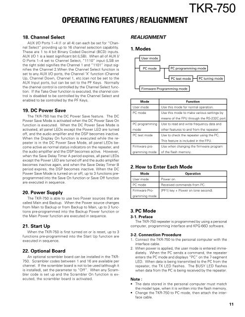
1. Modes<br />
User mode<br />
PC mode<br />
Mode<br />
User mode<br />
PC mode<br />
Firmware Programming mode<br />
PC programming<br />
mode<br />
PC test mode<br />
Firmware programming<br />
mode<br />
PC programming mode<br />
PC test mode<br />
PC tuning mode<br />
Function<br />
Use this mode for normal operation.<br />
Use this mode to make various settings by<br />
means of the FPU through the RS-232C port.<br />
Use to read and write frequency data and<br />
other features to and from the repeater.<br />
Use to check the repeater using the PC.<br />
This feature is included in the FPU.<br />
Use when changing the firmware program<br />
of the flash memory.<br />
2. How to Enter Each Mode<br />
Mode<br />
User mode<br />
PC mode<br />
Firmware Programming<br />
mode<br />
Operation<br />
Power on.<br />
Received commands from PC.<br />
[PF1] key + Power on (one second).<br />
3. PC Mode<br />
3-1. Preface<br />
The <strong>TKR</strong>-<strong>750</strong> repeater is programmed by using a personal<br />
computer, programming interface and KPG-66D software.<br />
3-2. Connection Procedure<br />
1. Connect the <strong>TKR</strong>-<strong>750</strong> to the personal computer with the<br />
interface cable.<br />
2. When power is applied, the user mode is entered immediately.<br />
When the PC sends a command, the repeater<br />
enters the PC mode and displays “PC” on the 7-segment<br />
LED. When data is being transmitted to the PC from the<br />
repeater, the TX LED flashes. The BUSY LED flashes<br />
when data from the PC is being received by the repeater.<br />
Note :<br />
• The data stored in the personal computer must match<br />
the model type, when it is written into the flash memory.<br />
• Change the <strong>TKR</strong>-<strong>750</strong> to PC mode, then attach the interface<br />
cable.<br />
11


