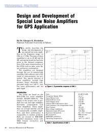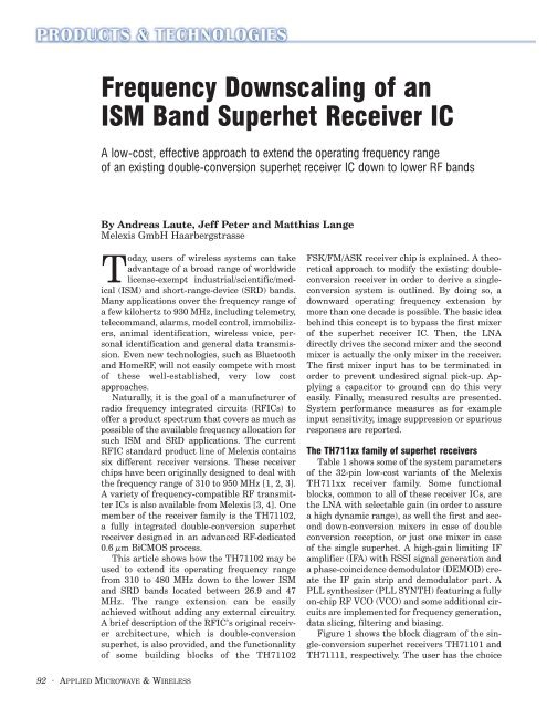
Frequency Downscaling of an ISM Band Superhet Receiver IC
Frequency Downscaling of an ISM Band Superhet Receiver IC
Frequency Downscaling of an ISM Band Superhet Receiver IC

Create successful ePaper yourself
Turn your PDF publications into a flip-book with our unique Google optimized e-Paper software.
<strong>Frequency</strong> <strong>Downscaling</strong> <strong>of</strong> <strong>an</strong><br />
<strong>ISM</strong> B<strong>an</strong>d <strong>Superhet</strong> <strong>Receiver</strong> <strong>IC</strong><br />
A low-cost, effective approach to extend the operating frequency r<strong>an</strong>ge<br />
<strong>of</strong> <strong>an</strong> existing double-conversion superhet receiver <strong>IC</strong> down to lower RF b<strong>an</strong>ds<br />
By Andreas Laute, Jeff Peter <strong>an</strong>d Matthias L<strong>an</strong>ge<br />
Melexis GmbH Haarbergstrasse<br />
Today, users <strong>of</strong> wireless systems c<strong>an</strong> take<br />
adv<strong>an</strong>tage <strong>of</strong> a broad r<strong>an</strong>ge <strong>of</strong> worldwide<br />
license-exempt industrial/scientific/medical<br />
(<strong>ISM</strong>) <strong>an</strong>d short-r<strong>an</strong>ge-device (SRD) b<strong>an</strong>ds.<br />
M<strong>an</strong>y applications cover the frequency r<strong>an</strong>ge <strong>of</strong><br />
a few kilohertz to 930 MHz, including telemetry,<br />
telecomm<strong>an</strong>d, alarms, model control, immobilizers,<br />
<strong>an</strong>imal identification, wireless voice, personal<br />
identification <strong>an</strong>d general data tr<strong>an</strong>smission.<br />
Even new technologies, such as Bluetooth<br />
<strong>an</strong>d HomeRF, will not easily compete with most<br />
<strong>of</strong> these well-established, very low cost<br />
approaches.<br />
Naturally, it is the goal <strong>of</strong> a m<strong>an</strong>ufacturer <strong>of</strong><br />
radio frequency integrated circuits (RF<strong>IC</strong>s) to<br />
<strong>of</strong>fer a product spectrum that covers as much as<br />
possible <strong>of</strong> the available frequency allocation for<br />
such <strong>ISM</strong> <strong>an</strong>d SRD applications. The current<br />
RF<strong>IC</strong> st<strong>an</strong>dard product line <strong>of</strong> Melexis contains<br />
six different receiver versions. These receiver<br />
chips have been originally designed to deal with<br />
the frequency r<strong>an</strong>ge <strong>of</strong> 310 to 950 MHz [1, 2, 3].<br />
A variety <strong>of</strong> frequency-compatible RF tr<strong>an</strong>smitter<br />
<strong>IC</strong>s is also available from Melexis [3, 4]. One<br />
member <strong>of</strong> the receiver family is the TH71102,<br />
a fully integrated double-conversion superhet<br />
receiver designed in <strong>an</strong> adv<strong>an</strong>ced RF-dedicated<br />
0.6 µm BiCMOS process.<br />
This article shows how the TH71102 may be<br />
used to extend its operating frequency r<strong>an</strong>ge<br />
from 310 to 480 MHz down to the lower <strong>ISM</strong><br />
<strong>an</strong>d SRD b<strong>an</strong>ds located between 26.9 <strong>an</strong>d 47<br />
MHz. The r<strong>an</strong>ge extension c<strong>an</strong> be easily<br />
achieved without adding <strong>an</strong>y external circuitry.<br />
A brief description <strong>of</strong> the RF<strong>IC</strong>’s original receiver<br />
architecture, which is double-conversion<br />
superhet, is also provided, <strong>an</strong>d the functionality<br />
<strong>of</strong> some building blocks <strong>of</strong> the TH71102<br />
FSK/FM/ASK receiver chip is explained. A theoretical<br />
approach to modify the existing doubleconversion<br />
receiver in order to derive a singleconversion<br />
system is outlined. By doing so, a<br />
downward operating frequency extension by<br />
more th<strong>an</strong> one decade is possible. The basic idea<br />
behind this concept is to bypass the first mixer<br />
<strong>of</strong> the superhet receiver <strong>IC</strong>. Then, the LNA<br />
directly drives the second mixer <strong>an</strong>d the second<br />
mixer is actually the only mixer in the receiver.<br />
The first mixer input has to be terminated in<br />
order to prevent undesired signal pick-up. Applying<br />
a capacitor to ground c<strong>an</strong> do this very<br />
easily. Finally, measured results are presented.<br />
System perform<strong>an</strong>ce measures as for example<br />
input sensitivity, image suppression or spurious<br />
responses are reported.<br />
The TH711xx family <strong>of</strong> superhet receivers<br />
Table 1 shows some <strong>of</strong> the system parameters<br />
<strong>of</strong> the 32-pin low-cost vari<strong>an</strong>ts <strong>of</strong> the Melexis<br />
TH711xx receiver family. Some functional<br />
blocks, common to all <strong>of</strong> these receiver <strong>IC</strong>s, are<br />
the LNA with selectable gain (in order to assure<br />
a high dynamic r<strong>an</strong>ge), as well the first <strong>an</strong>d second<br />
down-conversion mixers in case <strong>of</strong> double<br />
conversion reception, or just one mixer in case<br />
<strong>of</strong> the single superhet. A high-gain limiting IF<br />
amplifier (IFA) with RSSI signal generation <strong>an</strong>d<br />
a phase-coincidence demodulator (DEMOD) create<br />
the IF gain strip <strong>an</strong>d demodulator part. A<br />
PLL synthesizer (PLL SYNTH) featuring a fully<br />
on-chip RF VCO (VCO) <strong>an</strong>d some additional circuits<br />
are implemented for frequency generation,<br />
data slicing, filtering <strong>an</strong>d biasing.<br />
Figure 1 shows the block diagram <strong>of</strong> the single-conversion<br />
superhet receivers TH71101 <strong>an</strong>d<br />
TH71111, respectively. The user has the choice<br />
92 · APPLIED M<strong>IC</strong>ROWAVE & WIRELESS
▲ Figure 1. Single-conversion FSK superhet block diagram with external components.<br />
to configure <strong>an</strong> ASK, FM or FSK receiver by arr<strong>an</strong>ging<br />
the external components appropriately. An RF front-end<br />
filter should be used to achieve both a high degree <strong>of</strong><br />
image rejection <strong>an</strong>d good blocking immunity. For high<br />
frequencies (greater th<strong>an</strong> 100 MHz), the best trade-<strong>of</strong>f<br />
with respect to cost, perform<strong>an</strong>ce <strong>an</strong>d repeatability usually<br />
comes with a surface acoustic wave filter (SAWFIL).<br />
After pre-amplification by the LNA, the mixer (MIX1)<br />
downconverts the RF signal to the IF r<strong>an</strong>ge, where a ceramic<br />
filter sets the desired receiver b<strong>an</strong>dwidth <strong>an</strong>d,<br />
hence, defines its selectivity. A phase-coincidence<br />
<strong>Receiver</strong> <strong>IC</strong> TH71101 TH71102 TH71111 TH71112<br />
<strong>Frequency</strong> R<strong>an</strong>ge 310 to 480 MHz 310 to 480 MHz 800 to 950 MHz 800 to 950 MHz<br />
Supply R<strong>an</strong>ge 2.5 to 5.5V, FSK 2.5 to 5.5V, FSK 2.5 to 5.5V, FSK 2.5 to 5.5V, FSK<br />
2.2 to 5.5V, ASK 2.2 to 5.5V, ASK 2.2 to 5.5V, ASK 2.2 to 5.5V, ASK<br />
Supply Current 6.5 to 7.8 mA 6.5 to 7.8 mA 7.6 to 9.2 mA 7.6 to 9.2 mA<br />
St<strong>an</strong>dby Current < 50 nA < 50 nA < 50 nA < 50 nA<br />
Demodulation FSK, FM, ASK FSK, FM, ASK FSK, FM, ASK FSK, FM, ASK<br />
<strong>Frequency</strong> single superhet double superhet single superhet double superhet<br />
Conversion<br />
Input Sensitivity, –111 dBm, FSK –111 dBm, FSK –109 dBm, FSK –109 dBm, FSK<br />
narrow b<strong>an</strong>d –109 dBm, ASK –109 dBm, ASK –108 dBm, ASK –108 dBm, ASK<br />
(including RF @ 40 kHz IFBW @ 40 kHz IFBW @ 40 kHz IFBW @ 40 kHz IFBW<br />
front-end filter loss)<br />
Input Sensitivity, –104 dBm, FSK –104 dBm, FSK –102 dBm, FSK –102 dBm, FSK<br />
wide b<strong>an</strong>d –106 dBm, ASK –106 dBm, ASK –104 dBm, ASK –104 dBm, ASK<br />
(including RF @ 150 kHz IFBW @ 150 kHz IFBW @ 150 kHz IFBW @ 150 kHz IFBW<br />
front-end filter loss)<br />
Maximum –10 dBm, FSK –10 dBm, FSK –10 dBm, FSK –10 dBm, FSK<br />
Input Signal –20 dBm, ASK –20 dBm, ASK –20 dBm, ASK –20 dBm, ASK<br />
Image Rejection > 50 dB > 65 dB > 50 dB > 65 dB<br />
(including RF<br />
front-end filter loss)<br />
Spurious Emission < –65 dBm < –65 dBm < –65 dBm < –65 dBm<br />
Package LQFP32 LQFP32 LQFP32 LQFP32<br />
▲ Table 1. Parameters <strong>of</strong> the Melexis 32-pin TH711xx receiver family.<br />
demodulator, formed by <strong>an</strong><br />
internal mixer (MIX3) <strong>an</strong>d <strong>an</strong><br />
external ceramic resonator<br />
with two capacitors, performs<br />
both FSK <strong>an</strong>d FM modulation.<br />
The operational amplifier<br />
(OA) acts as a comparator that<br />
delivers a rail-to-rail output signal.<br />
In case <strong>of</strong> ASK reception,<br />
where the external FSK/FM<br />
components are not needed, the<br />
RSSI signal c<strong>an</strong> be directly<br />
taken to feed the OA, in this<br />
case constituting <strong>an</strong> adaptive<br />
threshold data slicer, in order to<br />
set up <strong>an</strong> ASK demodulator.<br />
The single-conversion superhet<br />
allows a reasonably high degree<br />
<strong>of</strong> image suppression by<br />
selecting a high IF, in addition<br />
to good front-end filtering [5]. A typically used IF is 10.7<br />
MHz. In this case, the RF front-end filter’s attenuation<br />
at 21.4 MHz <strong>of</strong>f the center frequency determines the<br />
image suppression, which is about 50 dB (measured<br />
value derived with TH71101 <strong>an</strong>d TH71111).<br />
The double-conversion approach c<strong>an</strong> be treated as the<br />
next step in the evolution <strong>of</strong> the superhet receiver. It<br />
should be used if higher values <strong>of</strong> image rejection are<br />
needed. Of course, other receiver concepts c<strong>an</strong> be employed<br />
toward the same goal; some <strong>of</strong> them are directconversion<br />
<strong>an</strong>d low-IF receivers. Direct-conversion<br />
receivers have <strong>an</strong> inherently<br />
high degree <strong>of</strong> image rejection<br />
(theoretically up to infinity),<br />
but they suffer from other problems,<br />
such as DC <strong>of</strong>fsets <strong>an</strong>d LO<br />
signal spurious emission [6].<br />
Low-IF receivers do image rejection<br />
electronically, but practical<br />
values are poor (around 30<br />
dB) [7]. With the Melexis receiver<br />
chips, the system designer<br />
has the choice to do a simple<br />
upgrade from the single to the<br />
double superhet, just by replacing<br />
either TH71101 with<br />
TH71102 (310 to 480 MHz) or<br />
TH71111 with TH71112 (800<br />
to 950 MHz). A corresponding<br />
double superhet application<br />
diagram is depicted in Figure 2.<br />
Here, a second mixer (MIX2)<br />
is needed to convert the first IF<br />
(IF1) to the second (IF2). Additionally,<br />
the PLL synthesizer<br />
has been modified slightly to<br />
94 · APPLIED M<strong>IC</strong>ROWAVE & WIRELESS
▲ Figure 2. Double-conversion FSK superhet block diagram with external components.<br />
deliver two LO signals (LO1 <strong>an</strong>d LO2) that drive the<br />
mixers. A simple external LC network between MIX1<br />
<strong>an</strong>d MIX2 acts as a b<strong>an</strong>d-pass filter for the IF1 signal.<br />
Considering the same frequency <strong>of</strong> 10.7 MHz, as for the<br />
single-conversion case, now as IF2, the values for the<br />
first IF may be in the order <strong>of</strong> 60 MHz (depending on the<br />
exact RF needed). This leads to a subst<strong>an</strong>tially higher<br />
degree <strong>of</strong> image rejection (65 dB measured) because the<br />
attenuation <strong>of</strong> the SAW front-end filter, taken approximately<br />
120 MHz away from its pass-b<strong>an</strong>d frequency, is<br />
now much higher th<strong>an</strong> at 21.4 MHz.<br />
Tr<strong>an</strong>sformation to a low-RF SCSH receiver<br />
<strong>Receiver</strong> <strong>IC</strong>s with fully integrated VCOs are very welcome<br />
to the system designer because there is no need for<br />
external VCO components, such as varactor diodes or inductors.<br />
On the other h<strong>an</strong>d, a fully integrated VCO typically<br />
has a limited LO frequency r<strong>an</strong>ge that restricts the<br />
receiver’s operating frequency<br />
r<strong>an</strong>ge. The frequency tr<strong>an</strong>slation<br />
scheme <strong>of</strong> a st<strong>an</strong>dard double-conversion<br />
superhet<br />
(DCSH) receiver follows the<br />
rule that the highest frequency<br />
<strong>of</strong> operation (high-RF) is downconverted<br />
by the first mixer to a<br />
lower frequency <strong>of</strong> operation<br />
(low-RF) that constitutes the<br />
first IF. A second mixer h<strong>an</strong>dles<br />
the next step <strong>of</strong> downconversion<br />
to derive the second IF. It<br />
follows logically that the operating<br />
frequency r<strong>an</strong>ge <strong>of</strong> a<br />
DCSH should be down-scalable,<br />
if the first mixer could be bypassed<br />
to make the second<br />
mixer’s input to be the terminal<br />
<strong>of</strong> the desired signal frequency<br />
(now the low-RF). Then, the DCSH is tr<strong>an</strong>sformed to a<br />
single-conversion superhet (SCSH) receiver.<br />
The TH71102 block diagram, shown in Figure 2,<br />
reveals that MIX1 ports IN_MIX1 <strong>an</strong>d IF1 are fully<br />
accessible. This gives the ch<strong>an</strong>ce to connect the LNA<br />
output not to the input <strong>of</strong> MIX1 but to the input <strong>of</strong><br />
MIX2. In this situation, MIX2 is the one <strong>an</strong>d only mixer<br />
in the system, able to receive low-RF signals. Figure 3<br />
outlines how the tr<strong>an</strong>sformation from DCSH to SCSH<br />
c<strong>an</strong> be realized by using the TH71102. As c<strong>an</strong> be seen<br />
from this application circuit, port LO1 <strong>of</strong> MIX1 c<strong>an</strong>not<br />
be disconnected because it is internal to the <strong>IC</strong>. Furthermore,<br />
the internal signal path from MIX1 to MIX2<br />
is fixed. This affects two issues:<br />
1. The input <strong>of</strong> MIX1 must be AC-grounded to prevent<br />
from picking up unw<strong>an</strong>ted high-RF signals that could be<br />
down-converted <strong>an</strong>d interfere with the desired low-RF,<br />
2. The output <strong>of</strong> MIX2 must be<br />
matched to the desired low-RF<br />
signal to keep parasitic LO1<br />
feed-through as low as possible.<br />
Both dem<strong>an</strong>ds c<strong>an</strong> be easily<br />
met — the first by applying a<br />
capacitor to pin IN_MIX1 that<br />
is well connected to ground,<br />
<strong>an</strong>d the second because the LC<br />
t<strong>an</strong>k at pins IF1P <strong>an</strong>d IF1N is<br />
trimmed to the desired low-RF.<br />
▲ Figure 3. Low-RF FSK superhet derived by DCSH-to-SCSH tr<strong>an</strong>sformation.<br />
The specified LO1 frequency<br />
r<strong>an</strong>ge <strong>of</strong> the TH71102 is 300 to<br />
450 MHz [8]. This tr<strong>an</strong>slates to<br />
<strong>an</strong> LO2 r<strong>an</strong>ge <strong>of</strong> 37.5 to 56.25,<br />
which is the new LO frequency<br />
r<strong>an</strong>ge <strong>of</strong> the receiver that has<br />
96 · APPLIED M<strong>IC</strong>ROWAVE & WIRELESS
een derived by DCSH-to-SCSH tr<strong>an</strong>sformation.<br />
Table 2 summarizes the new operating frequency<br />
r<strong>an</strong>ge <strong>of</strong> the SCSH. According to CEPT/ERC recommendation<br />
70-03 [9], the low-frequency services<br />
shown in Table 3 c<strong>an</strong> be covered by the modified<br />
TH71102 application circuit.<br />
Experimental data <strong>of</strong> the low-RF SCSH receiver<br />
A test board has been fabricated to validate the<br />
theoretical approach <strong>of</strong> the DCSH-to-SCSH tr<strong>an</strong>sformation.<br />
The board’s circuit schematic corresponds to<br />
Figure 3, with a receiving frequency <strong>of</strong> 40.68 MHz, the<br />
center frequency <strong>of</strong> one <strong>of</strong> the non-specific SRD b<strong>an</strong>ds.<br />
The receiver’s front-end RF filter characteristic is constituted<br />
by three separated LC b<strong>an</strong>d-pass filters (L2 <strong>an</strong>d<br />
C4; L3 <strong>an</strong>d C6; L4, L5 <strong>an</strong>d C9).<br />
A frequency sweep measurement c<strong>an</strong> be performed to<br />
check the system’s RF response without disturbing the<br />
LC filters’ imped<strong>an</strong>ces — a common RF test problem<br />
caused by the coupling effect <strong>of</strong><br />
the measurement system.<br />
The test configuration consists<br />
<strong>of</strong> a swept frequency signal<br />
generator to input the RF signal<br />
over the desired measurement<br />
frequency r<strong>an</strong>ge, <strong>an</strong>d a<br />
spectrum <strong>an</strong>alyzer operating in<br />
max hold mode to display the<br />
output signal at the IF port. In<br />
this case, the superhet receiver’s<br />
re-sponse is taken indirectly<br />
through its RF-to-IF conversion.<br />
Figure 4 shows the corresponding<br />
front-end filter characteristic,<br />
measured at pin<br />
OUT_MIX2, down-converted to<br />
the IF <strong>of</strong> 10.7 MHz.<br />
LO high-side injection LO low-side injection<br />
possible RFs LO – IF LO + IF<br />
r<strong>an</strong>ge <strong>of</strong> RFs (37.5 to 56.25)MHz – RF (37.5 to 56.25)MHz + IF<br />
r<strong>an</strong>ge <strong>of</strong> RFs 26.8 to 45.55 MHz 48.2 to 66.95 MHz<br />
at IF = 10.7 MHz<br />
▲ Table 2. Summary <strong>of</strong> the new operating frequency r<strong>an</strong>ge <strong>of</strong> the<br />
SCSH.<br />
While Figure 4 gives some insight in front-end selectivity,<br />
blocking <strong>an</strong>d image rejection capability <strong>of</strong> the<br />
receiver, the same measurement should be made with<br />
the spectrum <strong>an</strong>aly-zer picking up the signal behind the<br />
IF filter, in order to visualize the ch<strong>an</strong>nel selectivity. The<br />
result is depicted in Figure 5, showing the ceramic IF filter<br />
response with a 3 dB b<strong>an</strong>dwidth <strong>of</strong> 150 kHz.<br />
Table 4 summarizes the most import<strong>an</strong>t parameters<br />
in order to qu<strong>an</strong>tify the receiver’s perform<strong>an</strong>ce.<br />
Service <strong>Frequency</strong> R<strong>an</strong>ge Ch<strong>an</strong>nel Spacing Typical Applications<br />
Non-specific SRDs 26.957 to 27.238 MHz No ch<strong>an</strong>nels Telemetry, telecomm<strong>an</strong>d<br />
40.660 to 40.700 Mhz specified alarms, data in general <strong>an</strong>d<br />
other similar applications<br />
Model Control 26.995 to 27.195 MHz 10 kHz Controlling the movement<br />
34.995 to 35.223 MHz <strong>of</strong> a model<br />
40.665 to 40.695 MHz<br />
Inductive 26.957 to 27.283 MHz No ch<strong>an</strong>nels Car immobilizers, <strong>an</strong>imal<br />
Applications specified identification, alarm systems<br />
personal identification,<br />
proximity sensors, <strong>an</strong>titheft<br />
systems, automatic<br />
article identification<br />
Narrow-b<strong>an</strong>d audio 29.7 to 47.0 MHz 50 kHz Audio signal tr<strong>an</strong>smission<br />
▲ Table 3. Low-frequency services covered by the modified TH71102 application circuit.<br />
▲ Figure 4. <strong>Receiver</strong> RF front-end response, downcoverted<br />
to IF.<br />
▲ Figure 5. <strong>Receiver</strong> IF response behind the 150-kHz-wide<br />
ceramic filter.<br />
MAY 2001 · 97
Parameter Condition Value Unit<br />
St<strong>an</strong>d-by current ENRX at 0 V