RC5T583S PCB LAYOUT GUIDE - Ricoh
RC5T583S PCB LAYOUT GUIDE - Ricoh
RC5T583S PCB LAYOUT GUIDE - Ricoh

You also want an ePaper? Increase the reach of your titles
YUMPU automatically turns print PDFs into web optimized ePapers that Google loves.
<strong>RC5T583S</strong> <strong>PCB</strong> <strong>LAYOUT</strong> <strong>GUIDE</strong><br />
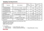
VIN0 GND VOUT<br />
LL0<br />
L<br />
LX<br />
FBP<br />
(4)<br />
LH0<br />
(3)<br />
Fig.1-8: Peripheral DCDC0 Evaluation Board Pattern 2 <br />
(3) Route the LH0/LL0 gate signal lines to FET to become the low resistance and not to become in parallel<br />
with a source of noise, such as a LX line.<br />
In the case of the LX line as one example; Connect the Lx line to FET at the 8 th layer of the evaluation<br />
board.<br />
(4) Route the VFB (FBP) line not to become in parallel with the LX line and under the coil pattern.<br />
In the case of the VFB line as one example; Route the VFB line for a feedback from output at the 5 th layer<br />
of the evaluation board.<br />
©2012 Page 10