Rigging and Installation Manual - Evapco
Rigging and Installation Manual - Evapco
Rigging and Installation Manual - Evapco

Create successful ePaper yourself
Turn your PDF publications into a flip-book with our unique Google optimized e-Paper software.
Low Profile Forced Draft Towers, Coolers <strong>and</strong> Condensers<br />
Final Assembly <strong>and</strong> Start-up Details<br />
Shipping Materials - Remove any wood chocks, spare parts, or miscellaneous items that have been placed inside the unit for<br />
shipping purposes. Clean all debris from the basin.<br />
Pump Discharge Line - Connect the riser pipe from the pump discharge on the pan-fan section to the riser pipe on the coil section<br />
using the flexible connection <strong>and</strong> hose clamps provided.<br />
Bleed-off Line - A bleed-off line <strong>and</strong> valve are installed on the unit when shipped with a pump. On units shipped without a pump<br />
(remote sump applications) make sure a bleed-off line <strong>and</strong> valve are properly sized <strong>and</strong> installed on the discharge side of the pump<br />
<strong>and</strong> connected to a convenient drain. In either case, the bleed-off valve should be fully open.<br />
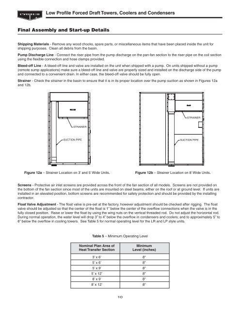
Strainer - Check the strainer in the basin to ensure that it is in its proper location over the pump suction as shown in Figures 12a<br />
<strong>and</strong> 12b.<br />
STRAINER<br />
STRAINER<br />
SUCTION PIPE<br />
SUCTION PIPE<br />
Figure 12a – Strainer Location on 3’ <strong>and</strong> 5’ Wide Units.<br />
Figure 12b – Strainer Location on 8’ Wide Units.<br />
Screens - Protective air inlet screens are provided across the front of the fan section of all models. Screens are not provided on<br />
the bottom of the fan section since most of the units are mounted on steel beams, either on the roof or at ground level. If units are<br />
installed in an elevated position, bottom screens are recommended for safety protection <strong>and</strong> should be provided by the installing<br />
contractor.<br />
Float Valve Adjustment - The float valve is pre-set at the factory, however adjustment should be checked after rigging. The float<br />
valve should be adjusted so that the center of the float is 1” below the center of the overflow connections when the valve is in the<br />
fully closed position. Raise or lower the float by using the wing nuts on the vertical threaded rod. Do not adjust the horizontal rod.<br />
During normal operation, the water level will drop 3” to 4” below the overflow in condensers <strong>and</strong> coolers; <strong>and</strong> to approximately 5” to<br />
6” below the overflow in cooling towers. See Table 5 for normal operating level for the LR <strong>and</strong> LP style units.<br />
Table 5 – Minimum Operating Level<br />
Nominal Plan Area of<br />
Heat Transfer Section<br />
Minimum<br />
Level (inches)<br />
3’ x 6’ 8"<br />
5’ x 6’ 8"<br />
5’ x 9’ 8"<br />
5’ x 12’ 8"<br />
8’ x 9’ 8"<br />
8’ x 12’ 8"<br />
10