Typical Ultra-CPA specifications - Evapco
Typical Ultra-CPA specifications - Evapco
Typical Ultra-CPA specifications - Evapco

Create successful ePaper yourself
Turn your PDF publications into a flip-book with our unique Google optimized e-Paper software.
TYPICAL <strong>Ultra</strong>-<strong>CPA</strong><br />
SPECIFICATIONS<br />
9-27-12<br />
UNIT CONSTRUCTION:<br />
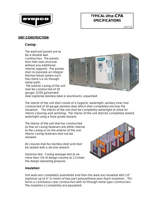
Casing:<br />
The wall/roof panels are to<br />
be a double wall<br />
construction. The panels<br />
form their own structure<br />
without any additional<br />
internal supports. The panels<br />
shall incorporate an integral<br />
thermal break system such<br />
that there is a no through<br />
metal path.<br />
The exterior casing of the unit<br />
shall be constructed of 18<br />
gauge, G235 galvanized<br />
steel (optional stainless steel or aluminum), unpainted.<br />
The interior of the unit shall consist of a hygienic watertight, sanitary inner liner<br />
constructed of 18 gauge stainless steel which shall completely enclose the<br />
insulation. The interior of the unit shall be completely watertight to allow for<br />
interior cleaning and sanitizing. The interior of the unit shall be completely sealed<br />
watertight using a food grade sealant.<br />
The interior of the unit shall be constructed<br />
so that all casing fasteners are either internal<br />
to the casing or on the exterior of the unit.<br />
Interior casing fasteners shall not be<br />
allowed.<br />
All closures shall be stainless steel and shall<br />
be sealed with a silicone sealant.<br />
Optional test: Casing leakage test at no<br />
more than ½% of design volume at 1.5 times<br />
the design operating pressure.<br />
Insulation:<br />
Unit walls are completely assembled and then the walls are insulated with 2.6”<br />
(optional up to 4” or more) of two part polyurethane pour foam insulation. This<br />
forms a continuous case construction with no through metal type construction.<br />
The insulation is completely encapsulated.
Roof:<br />
The roof shall be a minimum of 18 gauge, G235 galvanized steel, standing seam<br />
type construction, pitched away from the service doors for good water runoff. (on<br />
<strong>CPA</strong> units size 12 and larger). All exterior seams are sealed air and water tight with<br />
an FDA approved sealant.<br />
The interior liner of the roof shall be 18 gauge stainless steel. The interior of the unit<br />
shall be completely sealed watertight using a food grade sealant.<br />
Drain Pans:<br />
Each section of the unit shall be complete with<br />
100% drainable double sloped drain pans, which<br />
shall be a minimum of 16 gauge, stainless steel.<br />
Each drain pan shall be fully welded and<br />
individually tested to ensure they are leak free.<br />
Pans are fully welded to the unit base frame<br />
creating a one piece pan/base construction.<br />
Each pan shall have a 1.5” MPT connection<br />
extended to the unit exterior.<br />
The underside of the pans/base of the unit shall<br />
be insulated with a minimum of 2.5” polyurethane foam insulated completely<br />
covering the frame and the bottom of the pans. This ensures a completely<br />
insulated base and an airtight construction and forma a vapor barrier. This<br />
underside insulation is then protected by 18 gauge, G235 galvanized steel sheets<br />
welded to the bottom of the unit base frame.<br />
The drain connection for the drain pans shall be designed so the pans drain out<br />
the bottom of the drain pan for full drain pan drainage with the drain connection<br />
then extending out the side of the unit. No standing water shall be allowed.<br />
Frame/Base:<br />
The frame on all <strong>CPA</strong> units size 12 and larger shall be constructed of a double 8”<br />
channel, G235 unpainted galvanized steel all welded frame.<br />
On <strong>CPA</strong> units size 8 and smaller, the base shall have a 10 gauge, G235 galvanized<br />
steel all welded frame.<br />
Base is designed to support the internal component loads without sagging,<br />
pulsating or oil canning.<br />
Removable lifting lugs shall be provided at the base of the corners of each section<br />
of the unit.<br />
When the return air or supply air is in the bottom of the unit, the opening shall be<br />
framed to prevent water from draining down the opening. Each opening shall<br />
have a removable stainless steel or FRP safety grating.<br />
2
Access Doors:<br />
Access doors shall be of a size and quantity to permit full access to all components<br />
for maintenance, inspection and cleaning. Door shall be sized to allow removal of<br />
all internal components with the exception of the cooling coils. Access doors shall<br />
be provided with an extruded aluminum full perimeter door frame. The frame<br />
extrusions shall be miter cut at the corners and assembled by mechanically staking<br />
the frame into concealed gussets made of extruded aluminum. All doors and<br />
door frames shall be thermally broke. Access doors shall incorporate tow<br />
continuous separate gasket seals around the entire periphery of the door.<br />
Each door shall be pressure injected with 2.5# of polyurethane foam per cubic<br />
foot of door.<br />
The interior panels shall be constructed of 24 gauge stainless steel and the exterior<br />
panels of G90 hot dipped galvanized steel.<br />
The doors shall be mounted to the frame by a minimum of two (2) stainless steel<br />
hinges.<br />
Optional – the doors shall be complete with an 8” x 8” plastic window and/or a<br />
test port with screwed cap.<br />
Each door shall be complete with a minimum of two (2) 90 degree handles,<br />
operable from the interior and the exterior of the unit.<br />
Outside and Return Air Dampers:<br />
The dampers shall be parallel blade (optional opposed<br />
blade), with nylon bearings and stainless steel spring loaded<br />
side closures.<br />
The construction shall be a minimum of 16 gauge stainless<br />
steel with a 12-gauge casing.<br />
The dampers shall have a low leak rating of less than 6.5<br />
CFM per square foot at 4” of differential static pressure.<br />
Blowers:<br />
The blower wheel shall be all aluminum, nonoverloading<br />
air foil type. Wheel shall be mounted<br />
directly on the motor, direct drive. Motor/blower<br />
assembly shall be mounted off the floor to provide<br />
maximum accessibility and cleanability.<br />
Assembly shall not be mounted to structure on the<br />
unit base/floor. Blower shall be complete with an<br />
inlet guard.<br />
3
The blower will be in the draw through position (optional – blow through position<br />
depending on the application).<br />
Optional - the blower shall be complete with a discharge screen.<br />
Optional – the fan section shall be complete with an<br />
I-beam assembly hung from the ceiling complete<br />
with a trolley to assist in the motor/blower removal.<br />
Beam shall be stainless steel and be mounted below<br />
the ceiling so the top of the beam can be cleaned.<br />
Each blower shall be test run at their operating speed<br />
prior to shipment. The blower(s) shall be balanced<br />
and records maintained of the readings.<br />
Motors:<br />
The motors shall be premium efficient, TEFC duty, NEMA design B with class F<br />
insulation, VFD ready.<br />
HEATING OPTIONS:<br />
Steam Coils:<br />
The steam coil shall have _______ rows and ________ fins per inch.<br />
The steam coil shall be in the reheat position (optional - pre-heat position).<br />
The steam coil shall be constructed with 035” wall copper tubes and 0.0095”<br />
thick aluminum fins (optional – heavier tubes and fins or stainless steel tubes and<br />
aluminum fins or cupro nickel tubes and aluminum fins).<br />
The coil shall be designed for a maximum operating pressure of 25 psi (optional -<br />
100 psi steam – note operating pressures over 40 psi require cupro nickel or<br />
stainless tubes).<br />
The capacity of the coil shall be _________ BTUH using _____ PSIG steam at the<br />
steam coil.<br />
The steam coil shall be designed for a ______° F design entering air temperature.<br />
The coil shall be designed for a maximum face velocity of 800 feet per minute.<br />
Optional: Face and bypass dampers on the steam coil. The dampers shall be<br />
the same construction as the other dampers in the unit.<br />
Coils shall be mounted off the floor for maximum cleanability and accessibility.<br />
Coils shall not be mounted on structure fastened to the floor/base.<br />
4
Hot Water or Glycol Heating Coils:<br />
The hot water coil (optional - glycol coil) shall have _______ rows and ________ fins<br />
per inch.<br />
The coil shall be supplied in the reheat position (optional - pre-heat position).<br />
The coil shall be constructed with 0.025” wall copper tubes and 0.014” thick<br />
aluminum fins (optional – heavier wall tubes and fins or stainless steel tubes and<br />
aluminum fins). Headers shall be stainless steel.<br />
The coil shall have ____________ BTUH capacity using _____° F hot water (optional<br />
- ___% glycol).<br />
The coil shall require __________ GPM of hot water (optional - ____% propylene<br />
glycol).<br />
The water (or glycol) coil pressure drop shall be ______ feet.<br />
The coil shall be designed for a ______° F design entering air temperature.<br />
The coil shall be designed for a maximum face velocity of 800 feet per minute.<br />
Coils shall be mounted off the floor for maximum cleanability and accessibility.<br />
Coils shall not be mounted on structure fastened to the floor/base.<br />
Hot Gas Ammonia Heating Coil:<br />
The hot gas ammonia coil shall have _______ rows and ________ fins per inch.<br />
The hot gas coil shall be supplied in the reheat position (optional - pre-heat<br />
position).<br />
The hot gas ammonia coil shall be constructed with stainless steel tubes and<br />
aluminum fins (optional: hot dipped galvanized steel construction, Thermal-Pac®<br />
design or all aluminum construction). Headers shall be stainless steel.<br />
The capacity of the coil shall be _________ BTUH using _____° F hot gas ammonia<br />
condensing temperature.<br />
The hot gas ammonia coil shall be designed for a ______° F design entering air<br />
temperature.<br />
The coil shall be designed for a maximum face velocity of 800 feet per minute.<br />
Coils shall be mounted off the floor for maximum cleanability and accessibility.<br />
Coils shall not be mounted on structure fastened to the floor/base.<br />
5
Direct Fired Heating Section:<br />
The unit shall be designed with a direct fired burner located in the outside air<br />
section of the unit. The direct fired burner shall have a cast header with stainless<br />
steel baffle plates.<br />
The burner shall have a ____________ BTUH capacity.<br />
The burner shall be designed for 1-5 PSI natural gas pressure (optional - 8-14” or<br />
high pressure systems above 5 PSI) and be fully modulating with a 25 to 1<br />
turndown ratio. Burner shall have adjustable profile plates.<br />
The controls shall be full modulating and be designed in accordance with<br />
Factory Mutual (FM) insurance guidelines.<br />
The gas train shall be complete with all safety devices and controls.<br />
Indirect Fired Heating Section:<br />
The unit shall be designed with a indirect fired heating section. The indirect fired<br />
burner shall be fully modulating. The heat exchanger, primary and secondary,<br />
shall be 400 series stainless steel and be complete with drain connection piped<br />
to the outside of the unit (Optional 304 stainless steel).<br />
The heat exchanger shall be complete with a drain connection piped to the to<br />
outside of the unit. Note: Proper disposal of any condensate shall be by the<br />
installation contractor.<br />
The burner shall have a ____________ BTUH input capacity and a ________BTUH<br />
output capacity.<br />
The burner shall be designed for 8-14” natural gas pressure. Note: gas pressures<br />
above 14” requires a pressure reducing valve.<br />
The controls shall be full modulating and be designed in accordance with UL.<br />
The gas train shall be complete with all safety devices and controls. Burners are<br />
available with two-stage and fully modulating control. Turndown shall be a<br />
minimum of 8 to 1 (optional 10 to 1 and 20 to 1).<br />
Heat exchanger shall be complete with flue stack and rain cap (shipped loose<br />
for field mounting).<br />
COOLING OPTIONS:<br />
Recirculating/ Direct Expansion/ Flooded Refrigerant Cooling Coils:<br />
The cooling coil shall have _______ rows and ________ fins per inch.<br />
6
The coil shall be designed for recirculating ammonia<br />
(minimum 3 to 1 feed rate) (optional - direct expansion or<br />
flooded).<br />
The coil shall have a ____ ton capacity using a _____ °F<br />
saturated suction temperature.<br />
The capacity of the coil shall be based on a mixed air<br />
entering temperature of _____ ° F dry bulb/ _____° F wet<br />
bulb.<br />
The coil(s) for ammonia use shall be constructed using<br />
0.025” wall stainless tubes and 0.014 thick flat aluminum<br />
fins. (maximum of 8 FPI) (Optional: aluminum coil with 0.058” thick aluminum<br />
tubes and 0.014” thick aluminum fins or hot dip galvanized steel coils or all<br />
stainless steel tubes and fins). Coil shall meet strength requirements of<br />
ASME/ANSI B31.5. All coils shall be charged with nitrogen prior to shipment. The<br />
coils shall have aluminum tube sheets and stainless covers.<br />
Option - The coil(s) for R-22, R-404a, or any of the similar refrigerants shall be<br />
constructed using 0.025” wall tubes copper tubes and 0.014” thick aluminum fins.<br />
Headers shall be stainless steel. All coils shall be charged with nitrogen prior to<br />
shipment. Coil shall meet strength requirements of ASME/ANSI B31.5. (Optional:<br />
stainless steel tubes and aluminum fins, all aluminum coils, and all stainless steel<br />
coils).<br />
The coil shall be designed for a maximum face velocity of 625 feet per minute.<br />
Coils shall be mounted off the floor for maximum cleanability and accessibility.<br />
Coils shall not be mounted on structure fastened to the floor/base.<br />
Coils are tested to 350 psig under water and shall be guaranteed for 250 psig<br />
working pressure.<br />
Chilled Water or Glycol Cooling Coils:<br />
The cooling coil shall have _____ rows and _____ fins per inch.<br />
The coil shall have a _____ ton capacity using _____ GPM of _____ °F chilled water<br />
(optional - ____% propylene glycol).<br />
The water (or glycol) pressure drop through the coil shall be ____ feet.<br />
The coil capacities are based on a ____° F dry bulb / ____° F wet bulb mixed air<br />
entering temperature.<br />
The coil shall be constructed with copper tubes and aluminum fins (optional - hot<br />
dipped galvanized steel, all aluminum construction, stainless steel tube and<br />
aluminum fins, or all stainless steel). Coil shall meet strength requirements of<br />
ASME/ANSI B31.5.<br />
7
FILTRATION:<br />
Coils shall be mounted off the floor for maximum cleanability and accessibility.<br />
Coils shall not be mounted on structure fastened to the floor/base.<br />
Prefilters:<br />
Prefilters shall have an average efficiency of 25- 30%, MERV 8 (optional higher<br />
MERV ratings), pleated filters, with synthetic media (optional - aluminum or<br />
stainless steel washable filters).<br />
The unit shall be supplied with one initial set of filters (option – the unit shall be<br />
supplied with two or more sets of filters).<br />
The filters are held in solid welded filter frames without holes, joints, and clips. NO<br />
“universal” type filter frames shall be used.<br />
Optional – prefilter differential pressure gauge to indicate when the filters should<br />
be changed or differential pressure transducer to provide filter pressure drop<br />
indication on the PLC.<br />
Final Filters:<br />
The final filters shall be a 95%. MERV 14, efficient, mircofine glass wet laid paper<br />
rigid type, disposable (the same material used in HEPA, absolute filters – optional<br />
synthetic type material). The final filter shall have a rating of 95% efficient on a 1<br />
micron particle size.<br />
Option – 99.97% DOP absolute HEPA filter. The media on the HEPA filter shall be a<br />
microfine glass. The HEPA filter shall have a rating of 99.97% on a 0.3 micron<br />
particle size. Option: An intermediate 65% filter is available with the HEPA<br />
filtration system.<br />
The filters shall be held in solid welded filter frames on the MERV 14 filters which<br />
have no holes, joints, and clips. In<br />
addition, the frames have no<br />
gaskets. The final filters have the<br />
gasket, providing new gasketing at<br />
each filter change. NO “universal”<br />
filter frames shall be used.<br />
The final filters are complete with a<br />
differential pressure gauge.<br />
Optional: filter pressure drop<br />
transducer to provide a pressure<br />
drop indication on the PLC.<br />
The unit is supplied with one set of final filters (optional - unit supplied with two or<br />
more sets of final filters).<br />
8
ACCESSORIES<br />
Outside Air Inlet Hood:<br />
The unit includes an outside air inlet hood constructed of G235 galvanized steel.<br />
The hood shall be complete with a bird screen (optional - insect screen, either<br />
aluminum or stainless steel).<br />
The hood shall be shipped separate from the unit.<br />
Integral Exhaust Section:<br />
The integral exhaust section shall be complete with (qty of fans) __” diameter<br />
direct drive exhaust fans located within the casing of the <strong>CPA</strong> unit.<br />
Each of the fans shall be constructed of with a cast aluminum hub and<br />
adjustable polypropylene blades. Fans are direct drive.<br />
Service for the integral exhaust fans shall be accomplished through full sized<br />
walk-in access doors (no internal hatches or confined spaces shall be allowed).<br />
Each fan shall be driven by a ___ H.P., TEFC or TEAO fan direct drive motor.<br />
Motors shall be VFD ready if used for pressure or economizer control.<br />
Each fan shall have a double low leakage gravity backdraft damper. Material<br />
to match inner liner and exterior casing material.<br />
Desiccant Dehumidification Section:<br />
The dehumidification section shall consist of<br />
a rotor (wheel) of media impregnated with<br />
a silica gel desiccant. The wheel shall<br />
consist of a process section (where the<br />
moisture is removed from the air stream)<br />
and a regeneration section (where the<br />
moisture is removed from the air stream).<br />
The section will include a heated<br />
regeneration section with a heat source to<br />
drive the moisture from the wheel. The heat<br />
source shall be direct fired natural gas<br />
(optional steam, electric, or indirect fired<br />
natural gas).<br />
Humidifiers:<br />
Dispersion type steam humidifier system for minimal absorption distance, with the<br />
capacity as required. Dispersion tubes shall be stainless steel with stainless steel<br />
closures when necessary. Steam supply and condensate return connections<br />
9
shall be extended to the exterior of the unit casing. System complete with<br />
electric valve operator, steam trap and strainer in the supply line.<br />
UVC Light Systems:<br />
The <strong>CPA</strong> units can be supplied with a UVC light system<br />
for either just the cooling coil(s) and coil pan(s) or can<br />
be supplied to provide UVC lighting for the whole unit.<br />
Light systems are compete with individual ballasts,<br />
mounted in a control panel on the outside of the unit.<br />
Bulbs are complete with a protective sleeve. The<br />
system includes an access door observation window<br />
and an access door safety switch so the light(s) will go<br />
off if the door is opened.<br />
Service Corridor:<br />
The unit shall be provided with a full access 60” wide service corridor the full<br />
length of the unit. Service vestibule shall be the same construction as the unit<br />
with the exception the liner will be galvanized steel. Floor shall be a flat floor.<br />
Interior includes a 3 KW unit heater with a thermostat for winter heating and a<br />
fan and inlet louver for summer ventilation.<br />
ELECTRIC CONTROLS:<br />
Each unit shall be supplied with a Allen Bradley PLC control system with a UL<br />
label. (optional –Electro mechanical system).<br />
The following are some of the many options which are available for control<br />
systems.<br />
• Main control panel, control<br />
transformer and terminal blocks with<br />
UL label.<br />
• Allen Bradley Compact Logix and<br />
Micro Logix systems. Control Logix<br />
available as an option. Systems are<br />
complete with a 600 panel view<br />
(optional larger panels available) in<br />
the door of the main panel.<br />
• Outside air and recirculated air<br />
controls which use outside air on an economizer.<br />
• Outside air and recirculated air controls providing a fixed amount of<br />
outside air.<br />
• Outside air damper controls for systems with100% makeup air.<br />
• Room thermostats or RTD’s (typically mounted in the return air of the unit).<br />
• Return air thermostat or RTD’s<br />
• Outside air thermostat or RTD’s<br />
• Motorized steam valve (field mounted). Trap by others.<br />
• Magnetic motor starters mounted in the control panel.<br />
• Disconnect switches mounted in the control panel.<br />
10
• Arc flash disconnects<br />
• Remote stainless steel control panels which can include (just a few of the<br />
possible options):<br />
- blower on/off switch<br />
- blower indicating light<br />
- cleanup switch<br />
- cleanup indicating light<br />
- dirty filter light<br />
- burner Indicator light<br />
- PLC panel view<br />
• Steam coil freezestats.<br />
• Hot water or glycol 3-way control valves (shipped loose for field mounting)<br />
• Chilled water or glycol 3-way control valves (shipped loose for field<br />
mounting)<br />
• Room de-humidistat located in the remote<br />
control panel (or return air).<br />
• Natural gas heating controls – either direct or<br />
indirect fired.<br />
• Discharge air ammonia detector.<br />
• Smoke detectors.<br />
• CO2 detectors<br />
• O2 detectors<br />
• Hygienic interior service lights, watertight.<br />
• Service receptacles.<br />
• Automatic room pressurization control.<br />
• Heating coil face and bypass dampers and<br />
damper controls.<br />
• VFD motor control<br />
• Exhaust motor starters and or VFD drives<br />
• Cleanup cycle system and controls.<br />
• UVC coil/drain pan light systems.<br />
• Complete unit UVC light systems.<br />
• Blower door interlock switches (standard or CAT 3)<br />
• Dirty filter lights/contacts.<br />
• ASME surge drums mounted on top of the unit.<br />
• PLC controls with customer specified alarms, interface, and data<br />
collection.<br />
TESTING:<br />
Each unit shall be fully tested prior to shipping. This shall include a full control<br />
check along with air flow measurement at as close to design statics as possible.<br />
Optional tests include casing leakage testing and sound testing.<br />
11