Turbine Wake Model for Wind Resource Software
Turbine Wake Model for Wind Resource Software
Turbine Wake Model for Wind Resource Software

Create successful ePaper yourself
Turn your PDF publications into a flip-book with our unique Google optimized e-Paper software.
EWEC 2006 <strong>Wind</strong> Energy Conference and Exhibition<br />
The wake area is thus:<br />
π<br />
A ( ) ( ( )) 2<br />
w<br />
x = Dw x − ACut − off<br />
(11)<br />
4<br />
where the last terms takes cut-off into account if the wake hits the ground surface.<br />
Now, each time a wake passes a turbine enshrouded within it, it must experience an expansion<br />
corresponding to the stream tube area expansion, ΔA T , ( eq.(6)). To take this into account we have<br />
modified the wake diameter model further as<br />
1/2<br />
⎡ x ⎤<br />
Dw( x) = DR<br />
max ⎢β,<br />
Γ+α ⎥ (12)<br />
⎣ DR<br />
⎦<br />
Here Γ is a dimensionless number, with a value of zero at x=0, and increasing in jumps every<br />
time a turbine is passed as<br />
A ( x, Γ+ΔΓ) −A ( x, Γ ) =Δ A (13)<br />
w w T<br />
The work by Frandsen et al. [6] indicates that the expansion coefficient α should vary with the<br />
thrust coefficient – in fact the indications go that it should be proportionally to it. However, in the<br />
present work the coefficient α is treated as a constant model parameter.<br />
3.2 Mosaic-tiles model<br />
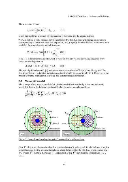
The concept of the mosaic speed deficit distribution is illustrated in fig.3. For a mosaic wake<br />
speed distribution the balance equation (9) takes the rather complicated <strong>for</strong>m:<br />
1<br />
n<br />
n<br />
T = A δ (1 −δ ) (14)<br />
2 ∑ i<br />
( k) ( k) ( k)<br />
U 1 1 ( k )<br />
0 i =<br />
∑∑<br />
ρ J J J<br />
k = J<br />
A 1<br />
A 12<br />
A 123<br />
<strong>Wake</strong> 1 A 1<br />
A 123<br />
<strong>Wake</strong> 2<br />
A 12<br />
<strong>Wake</strong> 1<br />
<strong>Wake</strong> 2<br />
<strong>Wake</strong> 3<br />
<strong>Wake</strong> 3<br />
A 13<br />
Affected rotor<br />
Affected rotor<br />
Ground<br />
Ground<br />
Figure 3. Examples of overlapping wake “mosaic-tiles” configurations.<br />
Here J (k) denotes a tile associated with a certain sub-set of k wakes, and A and δ indexed with this<br />
symbol denotes the tile area and the relative speed deficit within the tile. E.g., when considering<br />
n=3 wakes, J (1) can take the values [1] , [2] and [3], while J (2) may take the values [1,2], [1,3],<br />
[2,3].<br />
4