IPSYS â A new simulation tool for performance assessment and ...
IPSYS â A new simulation tool for performance assessment and ...
IPSYS â A new simulation tool for performance assessment and ...

You also want an ePaper? Increase the reach of your titles
YUMPU automatically turns print PDFs into web optimized ePapers that Google loves.
Paper submitted <strong>for</strong> WREC VIII, Denver, Colorado<br />
<strong>IPSYS</strong> – A <strong>simulation</strong> <strong>tool</strong> <strong>for</strong> per<strong>for</strong>mance <strong>assessment</strong> <strong>and</strong> controller development of<br />
integrated power system distributed re<strong>new</strong>able energy generated <strong>and</strong> storage<br />
Henrik Bindner, Oliver Gehrke, Per Lundsager, Jens Carsten Hansen<br />
Risø National Laboratory, Wind Energy Department, P.O.Box 49, DK-4000, Roskilde, Denmark<br />
Communication: henrik.bindner@risoe.dk<br />
An essential part of rural development is the supply of electrical energy. In particular, electrical<br />
energy is used <strong>for</strong> household appliances, telecom, clean water <strong>and</strong> many other services to the local<br />
community. This requires up to st<strong>and</strong>ards power quality <strong>and</strong> reliability. There is a push <strong>for</strong> exploitation<br />
of local re<strong>new</strong>able energy resources such as wind, <strong>and</strong> a battery system will often be an option<br />
<strong>for</strong> further reduction of fossil fuel consumption. Even though such types of systems can be quite<br />
complex, there is a need during the feasibility study, design <strong>and</strong> evaluation phases of a development<br />
project to be able to assess their per<strong>for</strong>mance.<br />
A key factor in this <strong>assessment</strong> is the ability to accurately model the power system. This<br />
includes accurate modelling of the actual control of the system, voltages <strong>and</strong> frequency, as well as<br />
losses. A <strong>new</strong> <strong>simulation</strong> <strong>tool</strong>, <strong>IPSYS</strong>, has been developed <strong>for</strong> that purpose. The core of the <strong>tool</strong> is a<br />
multi busbar load flow calculation <strong>for</strong> explicit modelling of voltage <strong>and</strong> frequency combined with<br />
the possibility of explicit modelling of other services e.g. water production <strong>and</strong> supply. This is<br />
combined with very flexible controller modelling that makes it possible to include the detailed<br />
behaviour of e.g. a battery energy storage in the system overall controls.<br />
The <strong>IPSYS</strong> <strong>simulation</strong> <strong>tool</strong> will be presented illustrating its potential <strong>for</strong> modelling systems<br />
with wind, storage <strong>and</strong> diesel gensets in different grid layouts <strong>and</strong> with different controllers.<br />
1 Introduction<br />
Throughout the world many places exist where there is no power or where there are small<br />
autonomous diesel grids. It is essential <strong>for</strong> these communities that there is a supply of electrical power<br />
in order to provide services that can support their development <strong>and</strong> assist in the generation of<br />
local income. These services include telecom, clean water, health clinics <strong>and</strong> power <strong>for</strong> households<br />
<strong>and</strong> small workshops/industries. In many of the places there is a push <strong>for</strong> exploitation of local re<strong>new</strong>able<br />
energy resources such as wind <strong>and</strong> sun. The systems that will be installed in such places<br />
can be quite complex in terms of configuration <strong>and</strong> operating strategy. The per<strong>for</strong>mance also heavily<br />
depends on the available resources <strong>for</strong> wind - this is particularly important since the resources<br />
can vary significantly even within small distances. For the successful completion of projects under<br />
these conditions, it is important to have a proven project procedure, which will include a technical<br />
(<strong>and</strong> derived economic) analysis of the system based on <strong>simulation</strong> results.<br />
In order to be able to analyse such systems, a development activity was initiated at Risø<br />
with the ambition to develop a <strong>simulation</strong> model that could be linked with a GIS (Geographical<br />
In<strong>for</strong>mation System), wind resource analysis software (WAsP, [1]), <strong>and</strong> would be able to model<br />
controllers. The current state of development of the model is that it can accept wind input from<br />
several sources including WAsP <strong>and</strong> it features very flexible controller modelling as well as a full<br />
load flow analysis, taking both active <strong>and</strong> reactive load sharing into account.<br />
2 Integrated power system <strong>simulation</strong><br />
Estimating the per<strong>for</strong>mance of isolated power systems through system <strong>simulation</strong> is a key<br />
activity of feasibility studies as well as in the development of operating strategies. Many <strong>simulation</strong><br />
models <strong>for</strong> hybrid systems have been developed during the last 20 years, [2]. An important initiative<br />
was an EU supported project in the beginning of the 1990s, which integrated five existing models<br />
<strong>for</strong> per<strong>for</strong>mance <strong>simulation</strong> of hybrid systems into a common framework, [3]. They were able to<br />
simulate a limited set of configurations of hybrid systems with predefined operating strategies.
Paper submitted <strong>for</strong> WREC VIII, Denver, Colorado<br />
At Risø, a <strong>tool</strong> <strong>for</strong> estimating the per<strong>for</strong>mance of wind diesel system was developed <strong>and</strong><br />
used in several feasibility projects, [4]. This model did not include energy storage <strong>and</strong> had only one<br />
operating strategy. Nevertheless did it prove to estimate the per<strong>for</strong>mance of such systems very well,<br />
but requires a lot of work <strong>and</strong> tweaking if it is to be used <strong>for</strong> other configurations.<br />
Current state of the art <strong>simulation</strong> <strong>tool</strong>s that are being applied in feasibility studies include<br />
Hybrid2, [5], <strong>and</strong> Homer, [6]. Hybrid2 can simulate a rather wide range of configurations as well as<br />
a number of predefined operating strategies, <strong>and</strong> it can also be used <strong>for</strong> a detailed <strong>simulation</strong> of system<br />
per<strong>for</strong>mance. Homer is a screening <strong>tool</strong> used to compare a number of specified configurations<br />
<strong>for</strong> their energy cost. The control strategy of the system cannot be set by the user.<br />
Despite their different origins, all of the above mentioned models have several important<br />
things in common: They are only able to simulate a limited set of configurations. The same is true<br />
<strong>for</strong> the operating strategies. All systems only model the active power balance, while reactive power<br />
is not considered. The power system is simulated as a single node i.e. the electrical grid is not<br />
explicitly modelled.<br />
The development of a <strong>new</strong> <strong>simulation</strong> package was considered after it had been realised<br />
that assessing the per<strong>for</strong>mance of a real system would require modelling that system in its particular<br />
configuration, together with the particular controller. As a first step a PhD study, [7], yielded a<br />
modular system <strong>simulation</strong> package. This package was very flexible in the modelling of the system<br />
configuration as it allowed <strong>for</strong> a virtually unlimited number of system components. Another key<br />
feature were generic controllers, which could adapt to configuration changes. It was also possible to<br />
change the operating strategy by changing control parameters instead of reprogramming the system.<br />
Another novel feature was the use of short time steps to study the effects of starting <strong>and</strong> stopping<br />
individual units. This permitted a more direct representation of the real controller.<br />
In many autonomous power systems with high penetration of re<strong>new</strong>able energy, other<br />
services such as supply of heat or water play an important role in the total economy of the system<br />
<strong>and</strong> will often be part of the project. It is there<strong>for</strong>e necessary to include them in the per<strong>for</strong>mance<br />
estimation. In many of these systems, derived services will have direct influence on the operation of<br />
the system, e.g. in a water production/supply system where the production of water depends on dem<strong>and</strong>,<br />
especially if no storage is available. The water production may even be a combination of<br />
thermal units fed from waste heat <strong>and</strong> electricity.<br />
Today there is an increased focus on power quality, even <strong>for</strong> small autonomous systems. In<br />
combination with creating the ability to integrate re<strong>new</strong>able resource data as well as community<br />
data (e.g. spatial in<strong>for</strong>mation on dwelling etc.) in a GIS <strong>for</strong> use in the planning phase of a system,<br />
explicit network modelling becomes a desirable feature <strong>for</strong> the per<strong>for</strong>mance estimation package.<br />
3 <strong>IPSYS</strong> – main features, architecture<br />
Experience has shown that there is a need <strong>for</strong> a model which falls between the simple<br />
models used in early phases of a feasibility study, <strong>and</strong> the dynamic models used <strong>for</strong> analysis <strong>and</strong><br />
design of dynamic controllers. The emphasis with this type of models is on the analysis <strong>and</strong><br />
development of system wide controllers (supervisory controllers) <strong>and</strong> operating strategies.<br />
The required main features of the <strong>simulation</strong> <strong>tool</strong> are:<br />
• Explicit modelling of the electrical network, i.e. load flow.<br />
• Explicit modelling of load sharing between generating units, <strong>for</strong> active <strong>and</strong> reactive power.<br />
• Flexible modelling of system configuration.<br />
• Flexible modelling of supervisory controllers.<br />
• Short time steps <strong>for</strong> accurate modelling of a supervisory controller.<br />
• Ability to explicitly include other circuits/balances that interact with the electrical system<br />
(<strong>and</strong> system control) in order to model other products/services.<br />
• Integration with the WAsP wind resource estimation <strong>tool</strong>.
Paper submitted <strong>for</strong> WREC VIII, Denver, Colorado<br />
Furthermore, the software needs to be easily extensible with <strong>new</strong> types of components, <strong>and</strong><br />
different sources of time series needed to be accepted as input, e.g. measured time series,<br />
synthesised time series <strong>and</strong> synthesised time series based on output from WAsP.<br />
The current version of the software includes a modified load flow algorithm that takes the<br />
active as well as reactive power load sharing explicitly into account. However, as a major constraint<br />
in the present version, all the units participating in the load sharing have to be connected to the<br />
same busbar. With this exception, the software allows <strong>for</strong> very flexible, user-configurable modelling<br />
of the system configuration, including individual representation of wind turbines <strong>and</strong> loads. It<br />
also has flexible controller modelling. The signals a controller can use are explicitly modelled <strong>and</strong><br />
controllers can be exchanged by the user. Each controller module still has to be hardcoded, but<br />
controller parameters can be included in the input files in order to tune the behaviour of a particular<br />
controller <strong>and</strong> controllers can be exchanged by editing the input file. The current version of the<br />
package has models <strong>for</strong> mechanical, heat <strong>and</strong> water circuits/balances, making it possible to<br />
explicitly model water production from both waste heat <strong>and</strong> electrical power in order to meet a<br />
specified dem<strong>and</strong>.<br />
4 Simulation examples<br />
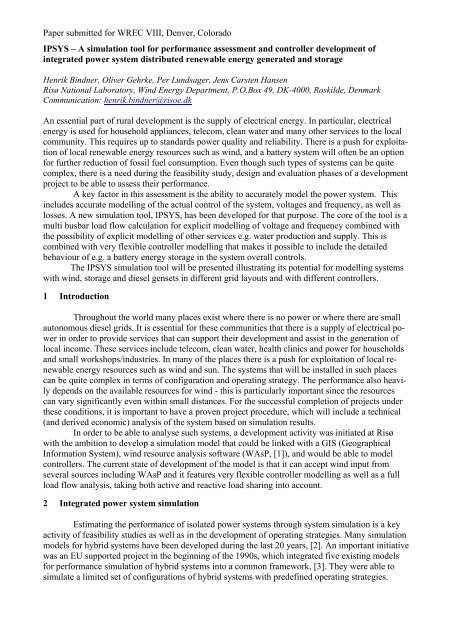
The scenario in Figure 1 is used to demonstrate the capabilities <strong>and</strong> potential of the <strong>IPSYS</strong><br />
package, <strong>and</strong>, as a sample application, to compare two different control strategies. The modelled<br />
system consists of four subsystems, corresponding to four physical domains, <strong>and</strong> is centered around<br />
an electrical minigrid of three busbars. Busbar 1 connects to a mechanical subsystem through two<br />
induction generators, each of which receives mechanical power from a wind turbine. Three sets of<br />
diesel generators feed electrical power into busbar 2, where a dump load is connected as well. The<br />
diesels’ speed governors are set to operate in droop mode, controlling system frequency, <strong>and</strong> each<br />
generator provides a regulated output voltage as a function of active <strong>and</strong> reactive power output. The<br />
third busbar feeds a time-variable consumer load <strong>and</strong> the pump of a reverse osmosis desalination<br />
plant. Busbars 1-2 <strong>and</strong> 2-3 are interconnected through non-ideal transmission lines.<br />
In addition to their connection to the electrical subsystem, both diesel gensets <strong>and</strong> the dump<br />
load are attached to a thermal subsystem, in which they serve as heat sources. They exchange<br />
Mechanical<br />
Bus 1 Bus 3<br />
Electric<br />
Wind Speed<br />
Gear Box<br />
Induction<br />
Generator<br />
Load<br />
Wind Turbine Rotor<br />
Wind Speed<br />
Gear Box<br />
Induction<br />
Generator<br />
Wind Turbine Rotor<br />
Bus 2<br />
Diesel Engine<br />
Diesel Engine<br />
Diesel Engine<br />
Synchronous Generator<br />
Synchronous Generator<br />
Synchronous Generator<br />
Dump Load<br />
Cooler<br />
Heat<br />
Evap<br />
desalination<br />
Electrical<br />
desalination<br />
Figure 1 Scenario<br />
Water
Paper submitted <strong>for</strong> WREC VIII, Denver, Colorado<br />
energy with a cooling unit <strong>and</strong> another desalination plant, which operates based on the evaporation<br />
method. Finally, the fourth domain is a freshwater subsystem, connecting the two desalination units<br />
to a time-variable water consumer.<br />
The thermal <strong>and</strong> freshwater circuits operate on a policy that attemps to maximize the utilisation<br />
of waste heat from diesel gensets <strong>and</strong> dumpload: The cooler only dissipates excess heat<br />
which can not be used <strong>for</strong> desalination, <strong>and</strong> the heat-driven desalination unit gets priority over the<br />
electricity-driven (reverse osmosis) one. This establishes a weak feedback loop across the thermal,<br />
water <strong>and</strong> electrical domains, as a decrease in diesel loading will reduce the amount of heat available<br />
<strong>for</strong> desalination. To meet water dem<strong>and</strong>, the throughput of the electric desalination unit will<br />
have to be raised, resulting in higher electricity dem<strong>and</strong> <strong>and</strong> thus higher diesel loading.<br />
Dispatching of the diesel generators is h<strong>and</strong>led by a system controller – implemented in a<br />
controller module – which decides based on the average load factor of all gensets. If the factor falls<br />
below a preset threshold, one of the generators is being taken off-line. Similarly, an additional unit<br />
is started if the utilisation factor rises above another threshold. To prevent on/off-cycling, a minimum<br />
runtime constraint <strong>for</strong>ces each genset to stay running <strong>for</strong> some time after having been started.<br />
In order to compare results from different runs, all input state variables (wind speeds, active<br />
<strong>and</strong> reactive consumer load, water dem<strong>and</strong>) receive their data from pre-generated timeseries instead<br />
of directly using one of the built-in timeseries generators. Result data from selected output variables<br />
is presented in Figure 2, gained from a run over 2000s of <strong>simulation</strong> time, at a timestep size of 5s.<br />
The control module is then being exchanged <strong>for</strong> another one with a different strategy, <strong>and</strong><br />
the <strong>simulation</strong> is run again. Controller #2 attempts to estimate the amount of spinning reserve required<br />
to prevent generator overload during the next timestep. The instantaneous values of fluctuating<br />
input quantities – wind, consumer load, water dem<strong>and</strong> – are summed up after a pre-set weighting<br />
scheme, to get an upper boundary <strong>for</strong> the expected load increase during one timestep. The generators<br />
are scheduled so that the sum of present load <strong>and</strong> expected load increase are within the cumulative<br />
rated capacity of all units on-line. The same minimum runtime policy is used as be<strong>for</strong>e.<br />
Figure 2: Selected <strong>simulation</strong> results. From top to bottom: Running state of diesel generators - active power<br />
data - busbar voltages - system frequency - freshwater dem<strong>and</strong> <strong>and</strong> production
Paper submitted <strong>for</strong> WREC VIII, Denver, Colorado<br />
Figure 3: Comparison of control strategies<br />
A comparison of both <strong>simulation</strong> runs is shown in Figure 3. Control strategy two (on the<br />
right) seems to have a better fuel efficiency, as can be seen from the increased use of available wind<br />
power, the smaller amount of energy consumed in the dump load, <strong>and</strong> shorter runtimes <strong>for</strong> each of<br />
the three diesel gensets. Fuel consumption data <strong>for</strong> each run is directly available from the <strong>simulation</strong><br />
output (although not shown in the figure) <strong>and</strong> indeed reveals an efficiency advantage of about 10%.<br />
Furthermore, control strategy one appears to result in inferior power quality, since large<br />
frequency spikes are visible in the left graph.<br />
5 Conclusion<br />
A <strong>new</strong> <strong>simulation</strong> <strong>tool</strong> <strong>for</strong> autonomous hybrid systems has been presented, which includes<br />
water production, bus bar voltages <strong>and</strong> exchangeable controllers in the analysis of a system.<br />
Future work on the <strong>tool</strong> involves validation, which is an ongoing activity, extension of the<br />
controller modelling to include a hierarchy of controllers as well as more components. A graphical<br />
user interface will also be developed to enable users outside of research to use the <strong>tool</strong>.<br />
References<br />
[1] Troen, I.; Mortensen, N.G.; Petersen, E.L.: WAsP. Wind Atlas Analysis <strong>and</strong> Application Programme,<br />
User’s Guide. Risø National Laboratory, Dept. of Meteorololy <strong>and</strong> Wind Energy,<br />
Roskilde 1988.<br />
[2] L.H. Hansen; P. Lundsager. Review of Relevant Studies of Isolated systems. Risø-R-1109.<br />
December 2000<br />
[3] D. Infield et al. Engineering Design Tools <strong>for</strong> Wind Diesel Systems. RAL-94-001<br />
[4] Delgado, J.; Hansen, J.C.; T<strong>and</strong>e, J.O.; Nørgård, P., Running-in <strong>and</strong> economic re-<strong>assessment</strong> of<br />
15% wind energy penetration in Cape Verde. In: Proceedings of EWEA special topic conference<br />
'95: The economics of wind energy. Helsinki (FI), 5-7 Sep 1995. Vihriälä, H. et al (eds)<br />
[5] Baring-Gould, E.I.; Green, H.J.; van Dijk, V.A.P.; Manwell, J.: Hybrid2 – The Hybrid Power<br />
System Simulation Model. NREL/TP-440-21506, Golden, CO 1996<br />
[6] Hybrid Optimization Model <strong>for</strong> Electric Re<strong>new</strong>ables (HOMER), National Re<strong>new</strong>able Energy<br />
Laboratory (www.nrel.gov/homer [as of April 2004])<br />
[7] Pereira, A. de L., Modular supervisory controller <strong>for</strong> hybrid power systems. Risø-R-1202(EN),<br />
Roskilde 2000 (PhD thesis)