Rittal PMC12 DC - Manual (Relay Card)
Rittal PMC12 DC - Manual (Relay Card)
Rittal PMC12 DC - Manual (Relay Card)

You also want an ePaper? Increase the reach of your titles
YUMPU automatically turns print PDFs into web optimized ePapers that Google loves.
2 Product Introduction<br />
<strong>Relay</strong> card for installation in <strong>Rittal</strong> <strong>PMC12</strong><br />
single phase ups-system. The card can be<br />
used at article numbers DK7857.430,<br />
DK7857.431, DK7857.432, DK7857.433 and<br />
DK7857.434.<br />
At the article numbers DK7857.433 and<br />
DK7857.434 the card can be installed in slot 1<br />
or 2.<br />
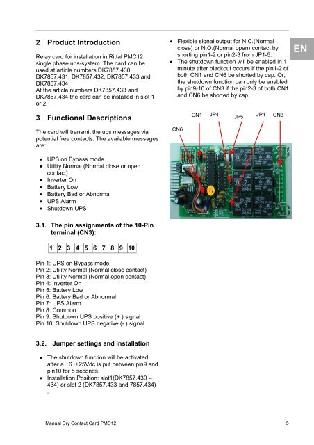
• Flexible signal output for N.C.(Normal<br />
close) or N.O.(Normal open) contact by<br />
shorting pin1-2 or pin2-3 from JP1-5.<br />
• The shutdown function will be enabled in 1<br />
minute after blackout occurs if the pin1-2 of<br />
both CN1 and CN6 be shorted by cap. Or,<br />
the shutdown function can only be enabled<br />
by pin9-10 of CN3 if the pin2-3 of both CN1<br />
and CN6 be shorted by cap.<br />
EN<br />
3 Functional Descriptions<br />
CN1<br />
JP4<br />
JP5<br />
JP1<br />
CN3<br />
The card will transmit the ups messages via<br />
potential free contacts. The available messages<br />
are:<br />
CN6<br />
• UPS on Bypass mode.<br />
• Utility Normal (Normal close or open<br />
contact)<br />
• Inverter On<br />
• Battery Low<br />
• Battery Bad or Abnormal<br />
• UPS Alarm<br />
• Shutdown UPS<br />
3.1. The pin assignments of the 10-Pin<br />
terminal (CN3):<br />
1 2 3 4 5 6 7 8 9 10<br />
Pin 1: UPS on Bypass mode.<br />
Pin 2: Utility Normal (Normal close contact)<br />
Pin 3: Utility Normal (Normal open contact)<br />
Pin 4: Inverter On<br />
Pin 5: Battery Low<br />
Pin 6: Battery Bad or Abnormal<br />
Pin 7: UPS Alarm<br />
Pin 8: Common<br />
Pin 9: Shutdown UPS positive (+ ) signal<br />
Pin 10: Shutdown UPS negative (- ) signal<br />
3.2. Jumper settings and installation<br />
• The shutdown function will be activated,<br />
after a +6~+25Vdc is put between pin9 and<br />
pin10 for 5 seconds.<br />
• Installation Position: slot1(DK7857.430 –<br />
434) or slot 2 (DK7857.433 and 7857.434)<br />
.<br />
<strong>Manual</strong> Dry Contact <strong>Card</strong> <strong>PMC12</strong> 5