Further information - Rittal
Further information - Rittal
Further information - Rittal

Create successful ePaper yourself
Turn your PDF publications into a flip-book with our unique Google optimized e-Paper software.
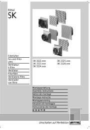
EN<br />
PSM (Power System Module / PCU)<br />
DK 7859.212<br />
DK 7859.222<br />
DK 7859.232<br />
DK 7859.215<br />
DK 7859.225<br />
DK 7859.235<br />
Assembly, installation and operation<br />
A34113 12 IT 74
Microsoft Windows is a registered trademark of Microsoft Corporation.<br />
Acrobat Reader is a registered trademark of Adobe Systems Incorporated.
Contents<br />
1 Notes on documentation...................4<br />
1.1 Other applicable documents ............................. 4<br />
1.2 Storing the documents ...................................... 4<br />
1.3 Symbols used.................................................... 4<br />
2 Safety instructions ............................4<br />
3 Device description.............................5<br />
3.1 Enclosure .......................................................... 5<br />
3.2 Power supply..................................................... 5<br />
3.3 Network properties ............................................ 5<br />
3.4 Scope of delivery............................................... 5<br />
3.5 Accessories....................................................... 6<br />
3.5.1 Required accessories (CMC-TC)........ 6<br />
3.5.2 Required accessories (external power<br />
pack) ................................................... 7<br />
3.6 Proper use......................................................... 7<br />
4 Assembly............................................8<br />
4.1 Notes for the assembly of the CMC-TC PU...... 8<br />
4.2 Assembling the CMC-TC .................................. 8<br />
4.3 Assembly of the PSM module in the PSM<br />
busbar ............................................................... 8<br />
4.4 Assembly of the PCU in the 19" level ............... 9<br />
5 Installation..........................................9<br />
5.1 Safety instructions and other notes................... 9<br />
6 Operation with power pack...............9<br />
6.1 Connecting further PSM modules (power pack<br />
operation) ........................................................ 10<br />
6.2 Specifying the current limit value (power pack<br />
operation) ........................................................ 10<br />
6.2.1 Specifying the lower current limit value<br />
(power pack operation) ..................... 10<br />
6.2.2 Specifying the upper current limit value<br />
(power pack operation) ..................... 10<br />
6.2.3 Limit values of the multicolour LED<br />
display ............................................... 10<br />
6.3 Assigning PSM module addresses (power pack<br />
operation) ........................................................ 10<br />
6.4 Configuring the display (power pack operation)<br />
10<br />
6.5 Resetting the PSM module to the factory setting<br />
(power pack operation) ................................... 11<br />
7 Operation with CMC-TC ..................11<br />
7.1 Connecting further PSM modules (CMC-TC<br />
operation) ........................................................ 11<br />
7.2 Assigning PSM module addresses (CMC-TC<br />
operation) ........................................................ 11<br />
7.3 Configuring the display (CMC-TC operation).. 12<br />
7.4 Resetting the PSM module to the factory setting<br />
(CMC-TC operation)........................................ 12<br />
Active 8-way PSM modules<br />
Notes on documentation 1<br />
7.5 Defining the PSM module on the CMC-TC PU II<br />
(CMC-TC operation) ........................................12<br />
8 Browser monitoring (as of SW 2.45)<br />
13<br />
8.1.1 Login ..................................................13<br />
8.1.2 Main page view..................................13<br />
8.1.3 General overview (status window).....13<br />
8.1.4 Monitoring using the browser ............13<br />
8.2 Individual current measurement ......................14<br />
8.2.1 Setup settings ....................................14<br />
8.2.2 Equipment settings ............................14<br />
8.2.3 Current measurement settings ..........16<br />
8.2.4 Installation position ............................16<br />
8.2.5 Log entries .........................................16<br />
8.2.6 Configuring the active PSM ...............17<br />
9 Maintenance and cleaning.............. 18<br />
9.1.1 Cleaning.............................................18<br />
10 Storage and disposal...................... 19<br />
10.1.1 Storage ..............................................19<br />
10.1.2 Disposal .............................................19<br />
11 Customer service ............................ 19<br />
12 Technical specifications................. 19<br />
13 Technical glossary.......................... 20<br />
14 Notes ................................................ 21<br />
3<br />
EN
1 Notes on documentation<br />
EN 1 Notes on documentation<br />
These instructions are intended for trained specialists<br />
who are familiar with the assembly, installation<br />
and operation of the PSM modules.<br />
Read these operating instructions prior to commissioning<br />
and be sure to keep them accessible for<br />
later use.<br />
<strong>Rittal</strong> can accept no liability for damage and operating<br />
disturbances resulting from non-compliance with<br />
these instructions.<br />
1.1 Other applicable documents<br />
In addition to these instructions, the instructions of<br />
other PSM components and their safety instructions<br />
apply.<br />
1.2 Storing the documents<br />
These instructions and all other applicable documents<br />
constitute an integral part of the product.<br />
They must be given to the device operator. The<br />
device operator is responsible for the storage of the<br />
documents so that they are readily available when<br />
needed.<br />
1.3 Symbols used<br />
Please note the following safety instructions and<br />
other notes in these instructions:<br />
Symbol for an instructed action:<br />
The bullet point indicates that you should perform an<br />
action.<br />
Safety instructions and other notes:<br />
Danger!<br />
Immediate danger to life and limb!<br />
Caution!<br />
Potential threat to the product and the<br />
environment.<br />
Note!<br />
Useful <strong>information</strong> and special features.<br />
2 Safety instructions<br />
Please observe the following general safety instructions<br />
when installing and operating the device:<br />
- Only a trained electrician, in particular for<br />
the cabling of enclosures with mains power,<br />
may perform assembly and installation of<br />
the PSM busbar. Other tasks associated<br />
with the PSM, such as the assembly and installation<br />
of system components with tested<br />
standard connectors, and the operation and<br />
configuration of the PSM modules may be<br />
performed only by instructed personnel.<br />
- Observe the applicable regulations governing<br />
electrical installations of the country in<br />
which the device is installed and operated<br />
as well as national regulations for accident<br />
prevention. Also observe company regulations<br />
(labour, operating and safety regulations).<br />
- Before performing any cabling work on the<br />
PSM system, it must be disconnected from<br />
the mains and secured against reactivation.<br />
- Use only genuine or recommended parts<br />
and accessories (see Chapter 3.5<br />
Accessories). The use of other parts can<br />
void the liability for any resulting consequences.<br />
- Do not make any changes to the PSM system<br />
other than those described in these instructions<br />
or associated instructions.<br />
- Operational reliability of the device is only<br />
guaranteed when used as intended. Under<br />
no circumstances may the tolerances specified<br />
in the technical specifications (see<br />
Chapter 12 Technical specifications) be exceeded.<br />
This applies in particular to the<br />
permissible ambient temperature range and<br />
permitted IP protection category. When<br />
used with a higher required IP protection<br />
category, the <strong>Rittal</strong> PSM system must be installed<br />
in a housing or enclosure with a<br />
higher IP protection category.<br />
- Operating the PSM system when it is in direct<br />
contact with water, corrosive substances<br />
or flammable gases and vapours is<br />
prohibited.<br />
- In addition to these safety instructions, it is<br />
imperative that the special safety instructions<br />
mentioned for the individual activities<br />
in the individual chapters are observed.<br />
4<br />
Active 8-way PSM modules
3 Device description<br />
The PSM is a modular power distribution system<br />
that can be snapped into a PSM busbar as appropriate<br />
for the requirements. The PSM modules are<br />
available in several variants. All modules described<br />
in these instructions can be monitored and administered<br />
in conjunction with the <strong>Rittal</strong> CMC-TC. The<br />
individual socket inserts can be switched for each<br />
module. Because all plug connections are shockhazard<br />
protected, the assembly and disassembly<br />
work does not need to be performed by a trained<br />
electrician.<br />
3.1 Enclosure<br />
Fig. 1<br />
PSM module, front side<br />
The PSM module is installed in its own aluminium<br />
housing. Catches on the outside edges are used to<br />
snap into the preinstalled PSM busbar. Each of the<br />
equipment slots located on the front side is standardised<br />
and made of plastic. The PSM module has<br />
a dual 7-segment display on the front side. When<br />
this is connected to the <strong>Rittal</strong> CMC-TC PU II or the<br />
external power pack (DK 7201.210), the currently<br />
consumed power of the complete module will be<br />
displayed. To monitor the individual slots, each of<br />
these is equipped with two LEDs that show the power<br />
currently being consumed at the slot. The LEDs<br />
can change between the colours green, orange and<br />
red. The associated limit values can be freely configured<br />
using the CMC. The front side also contains<br />
two LEDs that indicate the current electric circuit on<br />
which the PSM module is being operated.<br />
Fig. 2<br />
PSM module, rear side<br />
Various power supply sockets are located on the<br />
rear side of the PSM module. The PSM module will<br />
be supplied with power when it is snapped into the<br />
PSM busbar.<br />
3.2 Power supply<br />
The module will be supplied with power when it is<br />
snapped into the PSM busbar. All slots are activated<br />
as factory setting. To connect equipment, use the<br />
appropriate connection cable described in Chapter<br />
3.5 Accessories.<br />
Power is supplied to the 7-segment display either at<br />
the connection to the CMC-TC PU II or from an<br />
external power pack (DK 7201.210). A countryspecific<br />
connection cable is required when the power<br />
pack is used (see Chapter 3.5 Accessories).<br />
3.3 Network properties<br />
The connection of an RJ45 network cable to the<br />
Processing Unit allows the PSM module to be administered<br />
and monitored via a network. Read the<br />
Device description 3<br />
CMC-TC PU II operating instructions for details how<br />
this is done.<br />
The following values can be monitored and administered:<br />
- Activation and deactivation of the slots<br />
- Set the lower current limit value for alarming<br />
- Set the upper current limit value for alarming<br />
- Fetch the current power consumption<br />
- Set the limit values of the 3-colour LED<br />
power display (green, orange, red)<br />
- Status of the PSM module<br />
- Electric circuit connection (electric circuit 1<br />
or 2)<br />
- Time-controlled activation and deactivation<br />
(e.g. reboot the connected equipment)<br />
- Create switching combinations (e.g. various<br />
slots will be deactivated in case of a temperature<br />
alarm)<br />
- Forward alarm to an SNMP, SMS or e-mail<br />
recipient<br />
3.4 Scope of delivery<br />
The unit is supplied in a packaging unit in a fully<br />
assembled state.<br />
Please check the scope of delivery for completeness.<br />
Check the packaging carefully for any signs of damage.<br />
Quantity<br />
Designation<br />
1 PSM module<br />
2 1 RJ45 connection cable<br />
1 Operating instructions<br />
1 Commissioning checklist (German/English)<br />
Tab. 1<br />
Scope of delivery<br />
EN<br />
Active 8-way PSM modules<br />
5
EN<br />
3 Device description<br />
3.5 Accessories<br />
3.5.1 Required accessories (CMC-TC)<br />
The operation of the PSM module requires a fullyinstalled<br />
PSM busbar provided with power.<br />
You require the following accessories to administer<br />
and monitor the PSM module from the network.<br />
Designation<br />
Packs<br />
of<br />
Accessories<br />
Required<br />
Model<br />
no.<br />
IEC connector<br />
plug connection<br />
cable<br />
Country variant<br />
USA/CDN,<br />
UL-approval<br />
FT1/VW1<br />
IEC 320<br />
connector<br />
plug and<br />
socket extension<br />
cable<br />
1<br />
1<br />
7200.214<br />
7200.215<br />
CMC-TC<br />
components<br />
CMC-TC<br />
RJ45<br />
connection<br />
cable<br />
Mounting<br />
unit or<br />
module<br />
CMC-TC<br />
Processing<br />
Unit II<br />
CMC-TC<br />
power pack<br />
for CMC-TC<br />
Processing<br />
Unit II<br />
Installation<br />
bracket for<br />
CMC-TC<br />
power pack<br />
1 Yes 7320.100<br />
1 Yes 7320.425<br />
1 Yes 4597.000<br />
Length 0.5 m 1 Yes 7320.470<br />
Length 2 m 7320.472<br />
Length 5 m 7320.475<br />
Length 10 m 7320.481<br />
Length 15 m<br />
7320.485<br />
Mounting unit 1 Yes, 7320.440<br />
Cable clamp<br />
depending<br />
on<br />
strap for 1<br />
7611.000<br />
mounting unit<br />
the use<br />
Connection<br />
cable for<br />
equipment<br />
Connection<br />
cable<br />
C19/C20, 2 m<br />
Connection<br />
cable<br />
C13/C14, 0.5<br />
m<br />
Connection<br />
cable<br />
C13/C14, 2 m<br />
Connection<br />
cable country<br />
variant (D)<br />
earthing<br />
contact / C19<br />
Connection<br />
cable country<br />
variant (D)<br />
earthing<br />
contact / C14<br />
1<br />
1<br />
1<br />
1<br />
1<br />
Yes,<br />
depending<br />
on<br />
the use<br />
Tab. 2 Required accessories (CMC-TC)<br />
7200.217<br />
7856.014<br />
7200.215<br />
7200.216<br />
7200.210<br />
Mounting<br />
module<br />
1<br />
Yes,<br />
depending<br />
on<br />
the use<br />
7320.450<br />
Connection<br />
cable for<br />
DK<br />
7320.425<br />
power<br />
pack<br />
IEC connector<br />
plug connection<br />
cable<br />
Country variant<br />
D<br />
IEC connector<br />
plug connection<br />
cable<br />
Country variant<br />
GB<br />
Yes,<br />
once for<br />
1 the 7200.210<br />
power<br />
pack<br />
1<br />
7200.211<br />
IEC connector<br />
plug connection<br />
cable<br />
Country variant<br />
F/B<br />
IEC 320<br />
connector<br />
connection<br />
cable<br />
Country variant<br />
CH<br />
1<br />
1<br />
7200.210<br />
7200.213<br />
6<br />
Active 8-way PSM modules
Device description 3<br />
3.5.2 Required accessories (external<br />
power pack)<br />
The operation of the PSM module requires a fullyinstalled<br />
PSM busbar provided with power.<br />
equipment<br />
Connection<br />
cable<br />
C13/C14, 0.5<br />
m<br />
Connection<br />
cable<br />
C13/C14, 2 m<br />
1<br />
1<br />
the use<br />
7856.014<br />
7200.215<br />
EN<br />
You require the following accessories to operate the<br />
PSM without monitoring.<br />
Designation<br />
Packs<br />
of<br />
Accessories<br />
Required<br />
Model<br />
no.<br />
Connection<br />
cable country<br />
variant (D)<br />
earthing<br />
contact / C19<br />
1<br />
7200.216<br />
Power<br />
pack<br />
CMC-TC<br />
RJ45<br />
connection<br />
cable<br />
Connection<br />
cable for<br />
DK<br />
7201.210<br />
power<br />
pack<br />
Power pack<br />
for standalone<br />
operation<br />
Installation<br />
bracket for<br />
CMC-TC<br />
power pack<br />
1 Yes 7201.210<br />
1 Yes 4597.000<br />
Length 0.5 m 1 Yes 7320.470<br />
Length 2 m 7320.472<br />
Length 5 m 7320.475<br />
Length 10 m 7320.481<br />
Length 15 m<br />
IEC connector<br />
plug connection<br />
cable<br />
Country variant<br />
D<br />
IEC connector<br />
plug connection<br />
cable<br />
Country variant<br />
GB<br />
7320.485<br />
1 7200.210<br />
1<br />
7200.211<br />
Tab. 3<br />
Connection<br />
cable country<br />
variant (D)<br />
earthing<br />
contact / C14<br />
1<br />
7200.210<br />
Required accessories (external power pack)<br />
3.6 Proper use<br />
The <strong>Rittal</strong> PSM module serves as power supply or<br />
power distribution system. It can be connected to<br />
the <strong>Rittal</strong> CMC-TC monitoring system.<br />
Any use other than that described here is deemed<br />
improper. <strong>Rittal</strong> cannot accept any liability for damage<br />
associated with the failure to observe these<br />
instructions! Where applicable, the instructions for<br />
any used accessories also apply.<br />
IEC connector<br />
plug connection<br />
cable<br />
Country variant<br />
F/B<br />
IEC 320<br />
connector<br />
connection<br />
cable<br />
1<br />
1<br />
Yes,<br />
once for<br />
the<br />
power<br />
pack<br />
7200.210<br />
7200.213<br />
Country variant<br />
CH<br />
IEC connector<br />
plug connection<br />
cable<br />
Country variant<br />
USA/CDN,<br />
UL-approval<br />
FT1/VW1<br />
1<br />
7200.214<br />
IEC 320<br />
connector<br />
plug and<br />
socket extension<br />
cable<br />
1<br />
7200.215<br />
Connection<br />
cable for<br />
Connection<br />
cable<br />
C19/C20, 2 m<br />
1 Yes,<br />
depending<br />
on<br />
7200.217<br />
Active 8-way PSM modules<br />
7
4 Assembly<br />
EN 4 Assembly<br />
4.1 Notes for the assembly of the CMC-<br />
TC PU<br />
Install the CMC-TC PU in an enclosure or in a suitable<br />
housing system so that it is also protected from<br />
external effects. Also consider not only the permissible<br />
ambient temperature and humidity operational<br />
areas, but also the application-relevant required IP<br />
degree of protection (see CMC-TC PU operating<br />
instructions).<br />
Attach the Velcro tapes to the CMC-TC PU housing<br />
and position the CMC-TC PU at the required attachment<br />
location.<br />
3<br />
2,4<br />
1,5<br />
4.2 Assembling the CMC-TC<br />
Fig. 5<br />
Assembly in the 1 U mounting unit<br />
1. Remove the two upper screws from the cover.<br />
2. Remove the cover.<br />
3. Push the CMC-TC PU onto the retaining plate of<br />
the mounting unit. Ensure that the retaining<br />
plate sits between the guide rails of the CMC-<br />
TC PU.<br />
4. Replace the cover on the mounting unit.<br />
5. Refasten the cover screws on the 1 U mounting<br />
unit.<br />
4.3 Assembly of the PSM module in the<br />
PSM busbar<br />
Fig. 3<br />
Assembly with mounting module<br />
Push the CMC-TC PU onto the retaining plate of the<br />
mounting module. Ensure that the retaining plate<br />
sits between the guide rails of the CMC-TC PU.<br />
Fig. 6<br />
Assembly of the PSM module in the<br />
PSM busbar<br />
Remove the PSM module from the packaging. Decide<br />
before the assembly which PSM busbar infeed<br />
should supply the module. Snap the PSM module<br />
into the busbar as shown in the upper picture.<br />
1<br />
Fig. 4<br />
Assembly with Velcro strips<br />
Remove the protective foil from the supplied Velcro<br />
tapes.<br />
Ensure that the adhesive surfaces are free from<br />
grease and dust.<br />
8<br />
Fig. 7<br />
Insert RJ45 cable<br />
Now remove the supplied RJ45 cable and insert one<br />
end of the RJ45 cable in the RJ45 socket (1). To<br />
Active 8-way PSM modules
ensure that the plug has snapped in correctly, listen<br />
for the noticeable clicking noise of the RJ45 plug<br />
during the insertion.<br />
To remove the plug again, press the latching catch<br />
of the RJ45 plug and pull carefully on the plug.<br />
4.4 Assembly of the PCU in the 19"<br />
level<br />
The <strong>Rittal</strong> PCU (7859.225 / 7859.235) has the same<br />
construction form as the PSM modules other than it<br />
has mounting brackets on the sides and its own 1-<br />
phase connection cable. This allows the PCU to be<br />
mounted directly in the 19" level of the rack.<br />
Turn the mounting bracket to allow the PCU to also<br />
be mounted vertically at the 19" level of the rack.<br />
Fig. 8<br />
Assembly of the PCU in the 19" level<br />
5 Installation<br />
Installation 5<br />
Danger!<br />
Properly trained specialists may only<br />
perform assembly and installation of<br />
the PSM busbar.<br />
5.1 Safety instructions and other notes<br />
- The <strong>Rittal</strong> PSM module may only be operated<br />
with PE conductor connection. The PE<br />
conductor connection is established when<br />
the PSM module is snapped into the PSM<br />
busbar.<br />
- The electrical connection voltage and<br />
frequency must match nominal values<br />
specified in the technical specifications (see<br />
Chapter 12 Technical specifications).<br />
- Before working on the <strong>Rittal</strong> PSM busbar, it<br />
must be disconnected from the mains and<br />
secured against reactivation.<br />
- Fasten the connection cables with cable ties<br />
in the immediate vicinity of the connection of<br />
the PSM busbar.<br />
- To prevent losses caused by unnecessary<br />
cable lengths, the used cable lengths must<br />
not exceed the lengths stated in the technical<br />
specifications (see Chapter 12 Technical<br />
specifications).<br />
6 Operation with power pack<br />
Insert the RJ45 cable in the RJ45 socket of the power<br />
pack (7201.210). During the insertion, ensure<br />
that you hear the noticeable clicking noise of the<br />
RJ45 plug.<br />
To remove the plug again, press the latching catch<br />
of the RJ45 plug and pull carefully on the plug.<br />
Insert the country-specific connection cable in the<br />
power pack and in a non-switchable PSM module.<br />
The display of the PSM module now indicates the<br />
electric circuit and "0.0" appears in the display.<br />
EN<br />
Two 3-colour LEDs (green, orange, red), labelled as<br />
"I" or "II".<br />
Each of these LEDs flashes appropriately depending<br />
on the installation position of the module.<br />
Parameter<br />
Green<br />
Orange<br />
Red<br />
Definition<br />
OK<br />
Warning, fuse activated or<br />
mains voltage absent<br />
Maximum or minimum current<br />
limit value was undershot or<br />
overshot<br />
Active 8-way PSM modules<br />
9
EN<br />
6 Operation with power pack<br />
6.1 Connecting further PSM modules<br />
(power pack operation)<br />
A maximum of four modules may be connected in<br />
series. Snap the module into the PSM busbar as<br />
described previously. Insert the RJ45 cable into the<br />
free socket of the first module and the other end in<br />
the RJ45 socket of the new module. During the insertion,<br />
ensure that you hear the noticeable clicking<br />
noise of the RJ45 plug.<br />
To remove the plug again, press the latching catch<br />
of the RJ45 plug and pull carefully on the plug.<br />
6.2 Specifying the current limit value<br />
(power pack operation)<br />
You can specify the current limit values for alarms. If<br />
these values are undershot or overshot, the 7-<br />
segment display will flash and show the actual current<br />
value. The button on the PSM module must be<br />
used to set the current limit values. Please proceed<br />
as follows.<br />
6.2.1 Specifying the lower current limit<br />
value (power pack operation)<br />
Press the button for three seconds. An "L" will appear<br />
in the display.<br />
Press the button again for three seconds until the<br />
digit "0" appears in the display.<br />
Press the button briefly to specify the lower alarm<br />
current limit value.<br />
Press the button for three seconds to save the current<br />
limit value. An "H" will appear in the display.<br />
Wait a few seconds until the display changes in the<br />
status display (actual current value).<br />
6.2.2 Specifying the upper current limit<br />
value (power pack operation)<br />
Press the button for three seconds. An "L" will appear<br />
in the display.<br />
Press the button briefly once until an "H" appears in<br />
the display.<br />
Press the button again for three seconds until the<br />
digits "15" appear in the display.<br />
Press the button briefly to specify the upper alarm<br />
current limit value.<br />
Press the button for three seconds to save the current<br />
limit value. An "A" will appear in the display.<br />
Wait a few seconds until the display changes in the<br />
status display (actual current value).<br />
6.2.3 Limit values of the multicolour LED<br />
display<br />
If the PSM module or the PCU is operated with power<br />
pack, the limit values for which the LEDs of the<br />
associated connection change colour cannot be<br />
changed. In this case, the default values are retained.<br />
Default values:<br />
7859.222, 7859.225:<br />
Up to 2 A: green, up to 5 A: orange, above 5 A: red<br />
7859.212, 7859.215, 7859.232, 7859.235:<br />
Up to 3 A: green, up to 10 A: orange, above 10 A:<br />
red<br />
6.3 Assigning PSM module addresses<br />
(power pack operation)<br />
Each module must be assigned an address for both<br />
stand-alone operation and PSM modules switched<br />
in series. Please proceed as follows.<br />
Fig. 9<br />
1<br />
Assign addresses (power pack operation)<br />
Press the button (1) on the PSM module for three<br />
seconds. An "L" will appear in the display.<br />
Then press the button twice briefly. An "A" will appear<br />
in the display.<br />
Now press the button for three seconds. A "0" will<br />
appear in the display.<br />
Press the button briefly until the address "1" appears<br />
in the display.<br />
Press the button for three seconds to save the address.<br />
A small rectangle will appear in the display.<br />
Wait a few seconds until the display changes in the<br />
status display (actual current value).<br />
Now assign an address to each module as described<br />
previously. The second module in the series<br />
receives the address "2", etc.<br />
If a module is connected to a different power pack,<br />
the address begins with "1" again.<br />
6.4 Configuring the display (power<br />
pack operation)<br />
The PSM module has an integrated position sensor.<br />
This is responsible for the correct reading of the<br />
display. The position sensor is activated as factory<br />
setting. This means when the PSM module is turned<br />
in the PSM busbar (to electric circuit 2), the display<br />
is not up but rather down. The display is turned<br />
10<br />
Active 8-way PSM modules
automatically so that the values can be read optimally.<br />
If the PSM busbar with the PSM modules is mounted<br />
in the raised floor, the position sensor does not<br />
know how the display should be. It is the same for<br />
the horizontal installation of the PCU (7200.001) in<br />
the 19" level.<br />
To predefine the position of the display, proceed as<br />
follows.<br />
Press the button for three seconds. An "L" will appear<br />
in the display.<br />
Press the button briefly twice until a small rectangle<br />
appears.<br />
Press the button again for three seconds until the<br />
digit "3" appears in the display.<br />
Press the button briefly to select the position of the<br />
display.<br />
• Digit “1”: If the PSM module with the display<br />
is mounted at the top (the black arrow on<br />
the PSM module points up).<br />
• Digit “2”: If the PSM module with the display<br />
is mounted at the bottom (the red arrow on<br />
the PSM module points up).<br />
• Digit “3”: Position sensor is activated (automatic<br />
display position).<br />
Press the button for three seconds to save the current<br />
limit value. A "CL" will appear in the display.<br />
Wait a few seconds until the display changes in the<br />
status display (actual current value).<br />
6.5 Resetting the PSM module to the<br />
factory setting (power pack operation)<br />
You can reset the PSM module to the factory setting.<br />
All settings, such as current limit values, addresses<br />
and position sensor, will be lost. Proceed as<br />
follows.<br />
Press the button (1) on the PSM module for three<br />
seconds. An "L" will appear in the display.<br />
Then press the button four times briefly. A flashing<br />
"CL" will appear in the display.<br />
Now press the button for three seconds. The display<br />
will clear for a few seconds and then show the actual<br />
current value.<br />
Reconfigure the PSM module.<br />
Operation with CMC-TC 7<br />
7 Operation with CMC-TC<br />
1 2<br />
3 4<br />
Fig. 10<br />
1<br />
2<br />
P-I C<br />
1<br />
I0I0I<br />
Power<br />
24 VDC<br />
max. 2,5 A<br />
Connection to the CMC-TC PU II<br />
Insert the RJ45 cable from the PSM module in a<br />
free RJ45 socket (1) with the connection identification<br />
1-4. During the insertion, ensure that you hear<br />
the noticeable clicking noise of the RJ45 plug.<br />
To remove the plug again, press the latching catch<br />
of the RJ45 plug and pull carefully on the plug.<br />
7.1 Connecting further PSM modules<br />
(CMC-TC operation)<br />
A maximum of four modules of the same type / same<br />
article number can be connected to a port of the<br />
CMC-TC PU II. The modules are connected successively<br />
using the supplied cables. If the length of<br />
the RJ45 cable is too short, a commercially available<br />
RJ45 patch cable can also be used (no crossover<br />
cable).<br />
If you want to connect more than four modules to<br />
the CMC-TC PU II, you must use the next free RJ45<br />
socket (1) on the CMC-TC PU II.<br />
Snap the module into the PSM busbar as described<br />
previously. Insert the RJ45 cable into the free socket<br />
of the first module and the other end in the RJ45<br />
socket of the new module. During the insertion,<br />
ensure that you hear the noticeable clicking noise of<br />
the RJ45 plug.<br />
To remove the plug again, press the latching catch<br />
of the RJ45 plug and pull carefully on the plug.<br />
7.2 Assigning PSM module addresses<br />
(CMC-TC operation)<br />
Each module must be assigned an address for both<br />
stand-alone operation and PSM modules switched<br />
in series. Please proceed as follows.<br />
1<br />
EN<br />
Fig. 11<br />
Assign addresses (CMC-TC)<br />
Press the button (1) on the PSM module for three<br />
seconds. An "L" will appear in the display.<br />
Then press the button twice briefly. An “A” will appear.<br />
Now press the button for three seconds. A "0" will<br />
appear in the display.<br />
Active 8-way PSM modules<br />
11
EN<br />
7 Operation with CMC-TC<br />
Press the button briefly until the address "1" appears.<br />
Press the button for three seconds to save the address.<br />
A small rectangle will appear in the 7-<br />
segment display. Now assign an address to each<br />
module as described previously. The second module<br />
in the series receives the address "2", etc.<br />
If a module is connected to a different socket of the<br />
CMC-TC PU II or to a different power pack, the address<br />
begins with "1" again.<br />
Note!<br />
Modules with different type / article numbers<br />
cannot be cascaded to a shared<br />
connection of the Processing Unit II. Only<br />
modules of the same type can be cascaded.<br />
For modules of different types, use<br />
different connections of the Processing<br />
Unit II.<br />
7.3 Configuring the display (CMC-TC<br />
operation)<br />
The PSM module has an integrated position sensor.<br />
This is responsible for the correct reading type of<br />
the display. The position sensor is activated as factory<br />
setting. This means when the PSM module is<br />
turned in the PSM busbar (to electric circuit 2), the<br />
display is not up but rather down. The display is<br />
turned automatically so that the values can be read<br />
optimally.<br />
If the PSM busbar with the PSM modules is mounted<br />
in the raised floor, the position sensor does not<br />
know how the display should be. It is the same for<br />
the horizontal installation of the PCU (7200.001) in<br />
the 19" level.<br />
To predefine the position of the display, proceed as<br />
follows.<br />
Press the button for three seconds. An "L" will appear<br />
in the display.<br />
Press the button briefly twice until a small rectangle<br />
appears.<br />
Press the button again for three seconds until the<br />
digit "3" appears in the display.<br />
Press the button briefly to select the position of the<br />
display.<br />
• Digit “1”: If the PSM module with the display<br />
is mounted at the top (the black arrow on<br />
the PSM module points up).<br />
• Digit “2”: If the PSM module with the display<br />
is mounted at the bottom (the red arrow on<br />
the PSM module points up).<br />
• Digit “3”: Position sensor is activated (automatic<br />
display position).<br />
Press the button for three seconds to save the current<br />
limit value. A "CL" will appear in the display.<br />
Wait a few seconds until the display changes in the<br />
status display (actual current value).<br />
7.4 Resetting the PSM module to the<br />
factory setting (CMC-TC operation)<br />
You can reset the PSM module to the factory setting.<br />
All settings, such as current limit values, addresses<br />
and position sensor, will be lost. Proceed as<br />
follows.<br />
Press the button (1) on the PSM module for three<br />
seconds. An "L" will appear in the display.<br />
Then press the button four times briefly. A flashing<br />
"CL" will appear in the display.<br />
Now press the button for three seconds. The display<br />
will clear for a few seconds and then show the actual<br />
current value.<br />
Reconfigure the PSM module.<br />
7.5 Defining the PSM module on the<br />
CMC-TC PU II (CMC-TC operation)<br />
When power is present at the PSM module and an<br />
address has been assigned, it will be detected automatically<br />
by the CMC-TC PU II.<br />
Legend<br />
Fig. 12<br />
1<br />
I0I0I<br />
1 2 3 4<br />
PSM module detection<br />
1 Alarm LED<br />
During the detection of the PSM module, the alarm<br />
LED begins to flash alternately red, yellow and<br />
green. Continue to press the C key on the front side<br />
of the CMC-TC PU II until the alarm LED illuminates<br />
green continually.<br />
12<br />
Active 8-way PSM modules
8 Browser monitoring (as of SW<br />
2.45)<br />
Open your browser in the usual manner. Enter in the<br />
address line the IP address of the CMC-TC Processing<br />
Unit. The login window will appear.<br />
Browser monitoring (as of SW 2.45) 8<br />
8.1.3 General overview (status window)<br />
1<br />
6<br />
3<br />
2<br />
EN<br />
8.1.1 Login<br />
4<br />
1<br />
2<br />
3<br />
Legend<br />
Fig. 13<br />
1 Username<br />
2 Password<br />
Login window<br />
3 Login or Clear button<br />
Enter in the login window the http user name and<br />
the http password of the Processing Unit.<br />
Factory setting:<br />
Username: admin<br />
Password: admin<br />
To confirm the input, click the Login button. To clear<br />
the input, click the Clear button.<br />
8.1.2 Main page view<br />
1 2<br />
Legend<br />
Fig. 15<br />
5<br />
Sensors overview<br />
1 Connection number and sensor name<br />
2 Link for configuring the sensor<br />
3 Status display of the sensor<br />
4 Warning or alarm status of the sensor<br />
Green: No warning / no alarm<br />
Yellow: Warning<br />
Red: Alarm (incorrect operation)<br />
5 Acknowledging events<br />
Click the Clear key to start timeouts, configuration<br />
changes or refresh of all connected sensors. This repolls<br />
the CMC-TC PU and the web page will be rebuilt.<br />
6 Connected PSM modules<br />
Black digits: Status display of the called PSM module<br />
White digits: Connected PSM module<br />
Grey digits: Unavailable or not connected PSM modules<br />
8.1.4 Monitoring using the browser<br />
3<br />
4<br />
5<br />
6<br />
7<br />
8<br />
9<br />
Legend<br />
Fig. 14<br />
1 Address bar<br />
2 Status window<br />
As shown above<br />
CMC-TC main page view<br />
3 IP address of the Processing Unit<br />
4 Link to the main page view<br />
5 Setup link<br />
6 Alarm and event logging link<br />
7 Administration link<br />
8 Username<br />
9 User logout<br />
Fig. 16<br />
Current:<br />
Status:<br />
Position:<br />
PSM module overview<br />
1<br />
2<br />
Display of the actual current value of<br />
the equipment attached to the active<br />
PSM (server, etc.)<br />
Indicates whether the entered current<br />
limit value is observed. A message<br />
will be issued if the limit value<br />
is undershot or overshot.<br />
Indicates at which electric circuit the<br />
module is connected (for the redundant<br />
supply of the PSM busbars)<br />
3<br />
Active 8-way PSM modules<br />
13
EN<br />
8 Browser monitoring (as of SW 2.45)<br />
8.2 Individual current measurement<br />
The PSM/PCU bars have their own current measurement<br />
for each switch output.<br />
The two LEDs integrated in the associated sockets<br />
indicate the status of the switch output:<br />
- LEDs off: Relay output switched off<br />
- LEDs flashing green: Relay output switched on /<br />
'Low' current limit value undershot<br />
- LEDs green: Relay output switched on / current<br />
consumption 'OK'<br />
- LEDs orange: Relay output switched on / 'Warning'<br />
current limit value overshot<br />
- LEDs red: Relay output switched on / 'High' current<br />
limit value overshot<br />
Figure 17 shows an example overview page with<br />
three installed modules in various installation positions.<br />
Switched on relay outputs are also shown blue on<br />
the web page.<br />
The individual currents of the individual relay outputs<br />
are shown as Tooltip when the mouse cursor is<br />
moved over the associated socket symbol.<br />
8.2.1 Setup settings<br />
Ten sensor values, ten output values and ten measured<br />
values can be configured for each connected<br />
module.<br />
Ten tabs can be selected for each module, where<br />
tabs 1 – 8 concern the settings for each individual<br />
port, tab 9 concerns the settings for the current<br />
measurement and tab 10 concerns the positioning<br />
or the orientation of the module in the PSM busbar.<br />
8.2.2 Equipment settings<br />
Tabs 1..8 are used to display or set the eight (or six)<br />
current measurement values of a module.<br />
These pages can be used to set the delay value of<br />
the output. This delay value acts only when the output<br />
is switched off, i.e. this output will be switched<br />
on again after the delay time has expired.<br />
The 'Combinations' button can be used to set the<br />
links for each relay output.<br />
'Switch Output' can be used to switch the relay output.<br />
Figures 18 to 20 show examples of the relay outputs<br />
in various states.<br />
Fig. 17<br />
Overview page<br />
An orange LED indicates a 'warning' at relay output<br />
1/5. The red LEDs indicate that relay output 3/3 has<br />
an alarm (overcurrent).<br />
Fig. 18<br />
Consumer 4 switched on and 'OK' status<br />
14<br />
Active 8-way PSM modules
Browser monitoring (as of SW 2.45) 8<br />
The 'Advanced' button can be used to switch to a<br />
second settings page (see Fig. 21). This page can<br />
be used to set the 'High', 'Warning' and 'Low' setpoints<br />
for each of the eight (six) relay outputs.<br />
Settings for the alarm type and the alarm recipients<br />
can also be made.<br />
EN<br />
Fig. 19<br />
Consumer 5 switched on and 'Warning'<br />
status<br />
Fig. 21<br />
Setting of the ,Advanced’ parameters<br />
Fig. 20<br />
Consumer 2 switched on and 'Too High'<br />
status<br />
Active 8-way PSM modules<br />
15
EN<br />
8 Browser monitoring (as of SW 2.45)<br />
8.2.3 Current measurement settings<br />
Tab 9 shows the total current ('Current PSM') and<br />
the overall status of each module (see Fig. 22).<br />
This page can be used to set the 'High', 'Warning'<br />
and 'Low' setpoints for the complete module.<br />
Settings for the alarm recipient and the alarm type<br />
can also be made here.<br />
Fig. 23<br />
Installation position settings<br />
8.2.5 Log entries<br />
An entry for each status change (e.g. switch, warning,<br />
alarm, etc.) is made in the 'Alarm Log'.<br />
The example in Fig. 24 shows which entries are<br />
made for switching and overshooting or undershooting<br />
the setpoints for individual consumers.<br />
Fig. 22<br />
Total current settings<br />
8.2.4 Installation position<br />
Tab 10 shows the installation position ('Position<br />
PSM') of the module (see Fig. 23).<br />
Fig. 24<br />
Entries for various states<br />
16<br />
Active 8-way PSM modules
8.2.6 Configuring the active PSM<br />
Navigation<br />
Main menu – Status – Click 1st current<br />
Parameter<br />
1...n<br />
Type<br />
Sensor Status<br />
Message Text<br />
Setpoint High<br />
Setpoint Low<br />
Delay<br />
Relay Output<br />
Accept<br />
Reset<br />
Definition<br />
Browser monitoring (as of SW 2.45) 8<br />
Connection number of the sensor.<br />
Sensor type. Will be detected<br />
automatically.<br />
Sensor status. Green = OK, red<br />
= alarm.<br />
Message text included when a<br />
warning/alarm message is sent.<br />
Enter here a designation that<br />
uniquely identifies your sensor,<br />
e.g. "Current Rack 1".<br />
Current limit which when overshot<br />
causes an alarm message<br />
to be issued.<br />
Current limit which when undershot<br />
causes an alarm message<br />
to be issued.<br />
Time in seconds that specifies<br />
how long the socket should<br />
remain switched on.<br />
Off = manual activation of the<br />
PSM module; On = manual<br />
deactivation of the PSM module.<br />
Accept the changes.<br />
Reset all entries that have not<br />
yet been saved by clicking the<br />
"Accept" button.<br />
Alarm Beeper<br />
Alarm Reset<br />
Trap Receiver<br />
Scheduled<br />
Alarm Off<br />
Send SMS<br />
Send eMail<br />
Accept<br />
Reset<br />
Navigation<br />
Beeper should sound (enable)<br />
or not sound (disable) for warning/alarm.<br />
Warning/alarm should be acknowledged<br />
automatically<br />
(Auto) or must be acknowledged<br />
by the operator (Manual).<br />
Set at which of the entered trap<br />
receivers the warning/alarm<br />
messages should be sent.<br />
Set which alarm configuration<br />
should be switched on or off.<br />
The individual functions can be<br />
defined from the "Setup – Timer"<br />
menu item.<br />
You can enter a maximum of<br />
four mobile telephone numbers<br />
that you entered previously for<br />
Setup – SMS-Unit; each number<br />
is separated with the "&"<br />
character (e.g. 1&2&3&4).<br />
You can enter a maximum of<br />
four e-mail addresses that you<br />
entered previously for Setup –<br />
eMail (SMTP); each address is<br />
separated with the "&" character<br />
(e.g. 1&2&3&4).<br />
Accept the changes.<br />
Reset all entries that have not<br />
yet been saved by clicking the<br />
"Accept" button.<br />
Main menu – Status – Click 2nd status<br />
EN<br />
Navigation<br />
Main menu – Status – Click 2nd status<br />
Parameter<br />
1...n<br />
Type<br />
Sensor Status<br />
Alarm Relay<br />
Definition<br />
Connection number of the sensor.<br />
Sensor type. Will be detected<br />
automatically.<br />
Sensor status. Green = OK, red<br />
= alarm.<br />
Alarm relay should switch (enable)<br />
or not switch (disable) for<br />
warning/alarm.<br />
Parameter<br />
1...n<br />
Type<br />
Sensor Status<br />
Trap Receiver<br />
Send SMS<br />
Definition<br />
Connection number of the sensor.<br />
Sensor type. Will be detected<br />
automatically.<br />
Sensor status. Green = OK, red<br />
= alarm.<br />
Set at which of the entered trap<br />
receivers the warning/alarm<br />
messages should be sent.<br />
You can enter a maximum of<br />
four mobile telephone numbers<br />
that you entered previously for<br />
Setup – SMS-Unit; each number<br />
is separated with the "&"<br />
character (1&2&3&4).<br />
Active 8-way PSM modules<br />
17
9 Maintenance and cleaning<br />
EN Send eMail You can enter a maximum of<br />
four e-mail addresses that you<br />
entered previously for Setup –<br />
eMail (SMTP); each address is<br />
separated with the "&" character<br />
(e.g. 1&2&3&4).<br />
9 Maintenance and cleaning<br />
The <strong>Rittal</strong> PSM module is a maintenance-free system.<br />
The housing does not need opening for installation<br />
or operation.<br />
Accept<br />
Reset<br />
Accept the changes.<br />
Reset all entries that have not<br />
yet been saved by clicking the<br />
"Accept" button.<br />
Note!<br />
Opening the housing or accessory components<br />
will invalidate any warranty or<br />
liability claims.<br />
9.1.1 Cleaning<br />
Caution!<br />
Danger of damage!<br />
Do not use aggressive substances<br />
such as cleaner's naphtha, acids, etc.,<br />
for cleaning the device as they may<br />
cause damage!<br />
To clean the housing, use a damp cloth.<br />
18<br />
Active 8-way PSM modules
10 Storage and disposal<br />
10.1.1 Storage<br />
If the device is not used over a longer period, we<br />
recommend that you disconnect the device from the<br />
mains and protect it against moisture and dust.<br />
<strong>Further</strong> <strong>information</strong> about the operational conditions<br />
is contained in the technical specifications.<br />
10.1.2 Disposal<br />
Because the PSM module consists mainly of the<br />
housing and circuit board components, when the<br />
device is no longer needed, it must be disposed of<br />
according to the regulations governing the recycling<br />
of electrical equipment.<br />
11 Customer service<br />
If you have technical questions, or questions regarding<br />
our product range, please contact the service<br />
address as follows:<br />
Storage and disposal 10<br />
12 Technical specifications<br />
Designation PSM module (7859.212)<br />
Designation PSM module (7859.222)<br />
Designation PSM module (7859.232)<br />
Enclosure<br />
Housing type<br />
Height<br />
Width<br />
Depth<br />
Weight without<br />
packaging<br />
Earthing<br />
Aluminium, anodised,<br />
plastic caps<br />
500 mm<br />
50 mm<br />
45 mm<br />
Approx. 0.5 kg<br />
Yes<br />
Protection category IP 20 acc. to EN 60529<br />
EN<br />
Tel.: +49 (0)2772/505-1855<br />
http://www.cmc-tc.com<br />
E-mail: info@rittal.com<br />
Note!<br />
In order that we can answer your queries<br />
fast and accurately, in your e-mails, always<br />
enter the item number in the subject<br />
row.<br />
<strong>Further</strong> <strong>information</strong> and the current operating instructions<br />
and updates of the <strong>Rittal</strong> CMC-TC can be<br />
downloaded from the Security section of the Rimatrix5<br />
homepage.<br />
Operational area<br />
Temperature<br />
Moisture<br />
Storage temperature<br />
Voltage range<br />
Max. current<br />
Max. start-up current<br />
Max. switching load<br />
Thermal protection<br />
+5° C to 45° C<br />
+41° F to 113° F<br />
5% to 95% relative humidity,<br />
non-condensing<br />
-20° C to 60° C<br />
-4° F to 140° F<br />
1-phase, 110-230 VAC,<br />
50/60 Hz<br />
10-16 A for 230 VAC,<br />
10-15 A for 110 VAC,<br />
depending on the country<br />
variant, refer to the rating<br />
plate<br />
25 A per slot for Ohmic<br />
load, 4 seconds for 10%<br />
ED<br />
4000 VA per slot<br />
16 A at 25° C; refer to the<br />
rating plate for the busbar!<br />
Derating factor 0.55<br />
at 55° C housing temperature<br />
Technical specifications (7859.212,.222,.232)<br />
Active 8-way PSM modules<br />
19
EN<br />
13 Technical glossary<br />
Designation PCU module (7859.215)<br />
Designation PCU module (7859.225)<br />
Designation PCU module (7859.235)<br />
Enclosure<br />
Housing type<br />
Height<br />
Aluminium, anodised,<br />
plastic caps<br />
1 height unit, 44.45 mm<br />
Width 482.6 mm (19")<br />
Depth<br />
Weight without<br />
packaging<br />
Earthing<br />
45 mm<br />
approx. 0.5 kg<br />
Yes<br />
Protection category IP 20 acc. to EN 60529<br />
Operational area<br />
Temperature<br />
Moisture<br />
Storage temperature<br />
Voltage range<br />
Max. current<br />
Max. start-up current<br />
Max. switching load<br />
Thermal protection<br />
+5° C to 45° C<br />
+41° F to 113° F<br />
5% to 95% relative humidity,<br />
non-condensing<br />
-20° C to 60° C<br />
-4° F to 140° F<br />
1-phase, 110-230 VAC,<br />
50/60 Hz<br />
10-16 A for 230 VAC,<br />
10-15 A for 110 VAC,<br />
depending on the country<br />
variant, refer to the rating<br />
plate<br />
25 A per slot for Ohmic<br />
load, 4 seconds for 10%<br />
ED<br />
4000 VA per slot<br />
16 A at 25° C; refer to the<br />
rating plate for the busbar!<br />
Derating factor 0.55<br />
at 55° C housing temperature<br />
13 Technical glossary<br />
CMC-TC<br />
CMC-TC (Computer Multi Control - Top Concept) is<br />
a <strong>Rittal</strong> product used to monitor network enclosure<br />
components.<br />
Internet Browser<br />
An internet browser can be used to display html<br />
pages (and pages that conform to a similar standard).<br />
In the case of CMC-TC PU, they can be configured<br />
using a user interface displayed with an<br />
internet browser.<br />
Link<br />
A link causes a jump to another internet page or<br />
establishes a connection between two internet pages.<br />
SNMP (Simple Network Management Protocol)<br />
The SNMP is a simple network management protocol<br />
based on TCP/IP. It was developed to monitor<br />
network components on a central management<br />
station.<br />
Telnet<br />
Telnet is a protocol for guest access to a remote<br />
server. The Telnet program provides the required<br />
client functions of the protocol.<br />
Trap<br />
Trap is the sending of SNMP messages.<br />
Trap Receiver<br />
The trap receiver is the receiver of SNMP messages.<br />
Web Access<br />
The Web Access is used to define the access possibility<br />
via the internet.<br />
PSM<br />
PSM (Power System Module) is a modular socket<br />
strip that can be populated according to customer<br />
requirements. It consists of a busbar in which the<br />
individual PSM modules can be snapped in.<br />
Connection<br />
Wieland GST18, 3-pole<br />
with appropriate adapter<br />
Technical specifications (7859.215,225,235)<br />
20<br />
Active 8-way PSM modules
14 Notes<br />
Notes 14<br />
EN<br />
Active 8-way PSM modules<br />
21