Sea-Doo 4-TEC Thermostat Kit - RIVA Racing
Sea-Doo 4-TEC Thermostat Kit - RIVA Racing
Sea-Doo 4-TEC Thermostat Kit - RIVA Racing

Create successful ePaper yourself
Turn your PDF publications into a flip-book with our unique Google optimized e-Paper software.
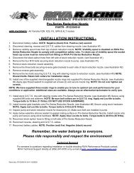
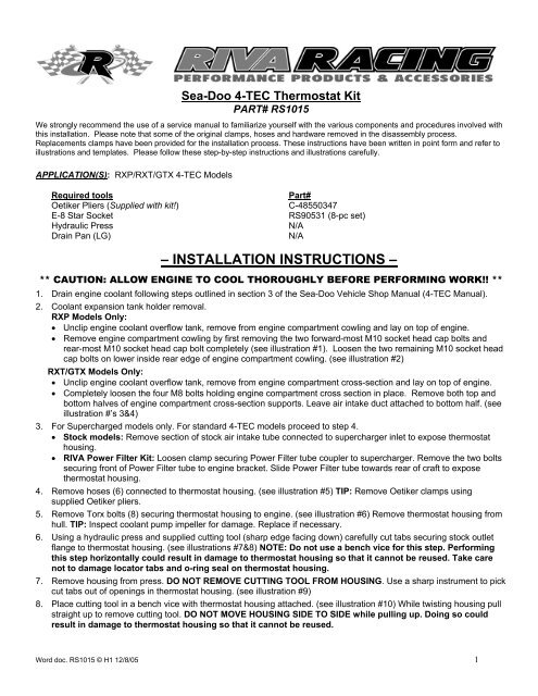
<strong>Sea</strong>-<strong>Doo</strong> 4-<strong>TEC</strong> <strong>Thermostat</strong> <strong>Kit</strong><br />
PART# RS1015<br />
We strongly recommend the use of a service manual to familiarize yourself with the various components and procedures involved with<br />
this installation. Please note that some of the original clamps, hoses and hardware removed in the disassembly process.<br />
Replacements clamps have been provided for the installation process. These instructions have been written in point form and refer to<br />
illustrations and templates. Please follow these step-by-step instructions and illustrations carefully.<br />
APPLICATION(S): RXP/RXT/GTX 4-<strong>TEC</strong> Models<br />
Required tools<br />
Part#<br />
Oetiker Pliers (Supplied with kit!) C-48550347<br />
E-8 Star Socket RS90531 (8-pc set)<br />
Hydraulic Press<br />
N/A<br />
Drain Pan (LG)<br />
N/A<br />
– INSTALLATION INSTRUCTIONS –<br />
** CAUTION: ALLOW ENGINE TO COOL THOROUGHLY BEFORE PERFORMING WORK!! **<br />
1. Drain engine coolant following steps outlined in section 3 of the <strong>Sea</strong>-<strong>Doo</strong> Vehicle Shop Manual (4-<strong>TEC</strong> Manual).<br />
2. Coolant expansion tank holder removal.<br />
RXP Models Only:<br />
• Unclip engine coolant overflow tank, remove from engine compartment cowling and lay on top of engine.<br />
• Remove engine compartment cowling by first removing the two forward-most M10 socket head cap bolts and<br />
rear-most M10 socket head cap bolt completely (see illustration #1). Loosen the two remaining M10 socket head<br />
cap bolts on lower inside rear edge of engine compartment cowling. (see illustration #2)<br />
RXT/GTX Models Only:<br />
• Unclip engine coolant overflow tank, remove from engine compartment cross-section and lay on top of engine.<br />
• Completely loosen the four M8 bolts holding engine compartment cross section in place. Remove both top and<br />
bottom halves of engine compartment cross-section supports. Leave air intake duct attached to bottom half. (see<br />
illustration #’s 3&4)<br />
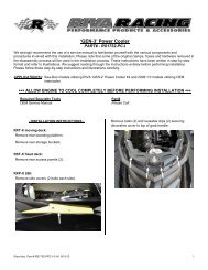
3. For Supercharged models only. For standard 4-<strong>TEC</strong> models proceed to step 4.<br />
• Stock models: Remove section of stock air intake tube connected to supercharger inlet to expose thermostat<br />
housing.<br />
• <strong>RIVA</strong> Power Filter <strong>Kit</strong>: Loosen clamp securing Power Filter tube coupler to supercharger. Remove the two bolts<br />
securing front of Power Filter tube to engine bracket. Slide Power Filter tube towards rear of craft to expose<br />
thermostat housing.<br />
4. Remove hoses (6) connected to thermostat housing. (see illustration #5) TIP: Remove Oetiker clamps using<br />
supplied Oetiker pliers.<br />
5. Remove Torx bolts (8) securing thermostat housing to engine. (see illustration #6) Remove thermostat housing from<br />
hull. TIP: Inspect coolant pump impeller for damage. Replace if necessary.<br />
6. Using a hydraulic press and supplied cutting tool (sharp edge facing down) carefully cut tabs securing stock outlet<br />
flange to thermostat housing. (see illustrations #7&8) NOTE: Do not use a bench vice for this step. Performing<br />
this step horizontally could result in damage to thermostat housing so that it cannot be reused. Take care<br />
not to damage locator tabs and o-ring seal on thermostat housing.<br />
7. Remove housing from press. DO NOT REMOVE CUTTING TOOL FROM HOUSING. Use a sharp instrument to pick<br />
cut tabs out of openings in thermostat housing. (see illustration #9)<br />
8. Place cutting tool in a bench vice with thermostat housing attached. (see illustration #10) While twisting housing pull<br />
straight up to remove cutting tool. DO NOT MOVE HOUSING SIDE TO SIDE while pulling up. Doing so could<br />
result in damage to thermostat housing so that it cannot be reused.<br />
Word doc. RS1015 © H1 12/8/05 1
9. Install supplied thermostat and o-ring into thermostat housing. (see illustration #11) NOTE: Apply waterproof<br />
grease to o-ring prior to installation.<br />
10. Place supplied billet outlet flange into thermostat housing at an angle. With locking tabs on outlet flange aligned with<br />
openings in thermostat housing carefully press outlet flange into thermostat housing. (see illustration #12)<br />
11. Using a hydraulic press and supplied cutting tool (sharp edge facing up) install supplied billet securing ring onto<br />
outside of thermostat housing. (see illustration #13) NOTE: Be sure sharp edge of cutting tool is facing up.<br />
Securing ring need only be seated onto thermostat housing. Use moderate pressure.<br />
12. Inspect o-ring on thermostat housing where it mates to engine. Install thermostat housing onto engine and secure<br />
using OE Torx bolts. Torque in specified order to 89 lbf•in / 10 N•m. (see illustration #14) NOTE: Apply blue Loctite<br />
to bolts. Do not over tighten bolts.<br />
13. Install supplied Oetikers onto cooling system hoses. (see illustration #15) Install hoses onto thermostat housing. (see<br />
illustration #16) Secure Oetiker clamps using supplied Oetiker pliers.<br />
14. For Supercharged models only. For standard 4-<strong>TEC</strong> models proceed to step 15. Replace air intake parts removed<br />
during step 3.<br />
15. Replace coolant following steps outlined in section 3 of the <strong>Sea</strong>-<strong>Doo</strong> Vehicle Shop Manual (4-<strong>TEC</strong> Models).<br />
Remember, the water belongs to everyone. Please ride responsibly!<br />
Technical Support<br />
For answers to questions regarding installation or trouble shooting <strong>RIVA</strong> Performance Products contact:<br />
<strong>RIVA</strong> Technical Support directly at (954) 247-0705 or by e-mail at tech_support@rivamotorsports.com<br />
Limited Warranty<br />
<strong>RIVA</strong> <strong>Thermostat</strong> <strong>Kit</strong>s carry a 90-day limited warranty to the original purchaser. They are warranted to be free of defects in materials and workmanship<br />
under normal use and service. Customer modified components will be void of warranty. This warranty is limited to defects in the primary components<br />
only. Finish and/or wear marks in or on primary components are not covered under this warranty.<br />
<strong>RIVA</strong> <strong>Racing</strong>’s liability is expressly limited to the repair or replacement of the components contained within or associated with this kit. <strong>RIVA</strong> <strong>Racing</strong><br />
agrees to repair or at <strong>RIVA</strong>’s option, replace any defective unit without charge, if product is returned to <strong>RIVA</strong> <strong>Racing</strong> freight prepaid within the warranty<br />
period. Any equipment returned which, in <strong>RIVA</strong>’s opinion, has been subjected to misuse, abuse, overheating or accident shall not be covered by this<br />
warranty.<br />
<strong>RIVA</strong> <strong>Racing</strong> shall have no liability for special, incidental or consequential damages or injury to persons or property from any cause arising from the<br />
sale, installation or use of this product.<br />
No other warranty, express or implied, including, but not limited to the implied warranties of merchantability and fitness for a particular purpose, applies.<br />
Various states do not allow for the limitation of incidental or consequential damages and therefore the above exclusion or limitation may not apply to<br />
you.<br />
Warranty does not include the expenses related to freight or transportation of parts or compensation for any inconvenience or loss of use while being<br />
repaired. A copy of the original invoice must accompany all warranty claims.<br />
Warranted replacement parts will be returned freight collect.<br />
Word doc. RS1015 © H1 12/8/05 2
– INSTALLATION IMAGES –<br />
Illustration 1 Illustration 2<br />
Illustration 3<br />
Illustration 4<br />
Word doc. RS1015 © H1 12/8/05 3
Hose removal order<br />
Illustration 5 Illustration 6<br />
Sharp edge<br />
of tool down.<br />
Depress until edge<br />
of tool meets edge of<br />
housing.<br />
Take care not to<br />
damage locator<br />
tabs and o-ring.<br />
Illustration 7 Illustration 8<br />
Word doc. RS1015 © H1 12/8/05 4
Pick out tabs using a<br />
sharp instrument.<br />
Twist housing while<br />
pulling STRAIGHT UP!<br />
Illustration 9 Illustration 10<br />
Install o-ring on top<br />
of thermostat.<br />
Place outlet flange<br />
into housing at angle.<br />
Press into housing.<br />
Ensure tabs are<br />
centered in openings<br />
in housing.<br />
Illustration 11<br />
Illustration 12<br />
Word doc. RS1015 © H1 12/8/05 5
Sharp edge<br />
of tool up.<br />
Depress until<br />
collar seats.<br />
7<br />
8<br />
Torque sequence<br />
89 lbf•in / 10 N•m<br />
5<br />
1<br />
6<br />
4<br />
2<br />
3<br />
Illustration 13 Illustration 14<br />
Size<br />
31.6<br />
Hose installation order<br />
Size<br />
30.1<br />
Size<br />
45.5<br />
Size<br />
31.6<br />
Size 38.1<br />
Size<br />
31.6<br />
Illustration 15 Illustration 16<br />
Word doc. RS1015 © H1 12/8/05 6