News from Rohde&Schwarz - Rohde & Schwarz
News from Rohde&Schwarz - Rohde & Schwarz
News from Rohde&Schwarz - Rohde & Schwarz

You also want an ePaper? Increase the reach of your titles
YUMPU automatically turns print PDFs into web optimized ePapers that Google loves.
Panorama<br />
High accuracy through automatic<br />
correction of frequency-response<br />
errors<br />
Reliable and fully automatic<br />
systems allowing the user to fully<br />
concentrate on the equipment<br />
under test<br />
Fully automatic monitoring and<br />
result logging of the equipment<br />
under test<br />
EMS Software EMS-K1:<br />
What’s new in version 1.20?<br />
Analysis mode:<br />
– Combination of automatic and<br />
manual scan, with free selection of<br />
frequency steps, variation of<br />
modulation parameters and change<br />
of antenna polarization and<br />
turntable position<br />
– Display of system parameters in<br />
test window<br />
– Reduction of test times by<br />
simultaneous measurement of<br />
forward and reflected power with<br />
two power meters<br />
EUT monitoring: interface for new EUT<br />
Monitoring Software EMON-K1<br />
EUT Monitoring Software<br />
EMON-K1: new ways<br />
for EUT monitoring<br />
Synchronous monitoring (complete<br />
measurement at each test frequency)<br />
or asynchronous operation (freerunning<br />
measurement) in combination<br />
with EMS Software EMS-K1<br />
Representation of measurement data<br />
in expressive graphical or tabular<br />
form<br />
Convenient reporting<br />
Storage of all setups and test results<br />
in ASCII and WMF format for further<br />
processing<br />
Monitoring and stimulus channels<br />
Device drivers can be created by user<br />
Graphical user interface and contextsensitive<br />
help<br />
Complete vehicle testing in large<br />
anechoic chamber<br />
Even if a high degree of reliability of<br />
the individual components is attained<br />
as a result of EMC testing during<br />
development, a final test of the<br />
assembled vehicle is indispensable.<br />
Once built-in, components might show<br />
a quite different behaviour than in the<br />
TEM cell or stripline.<br />
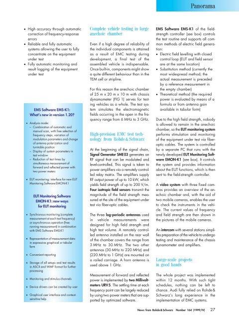
For this reason the anechoic chamber<br />
of 25 m x 20 m x 10 m with chassis<br />
dynamometer (FIG 1) serves for testing<br />
vehicles as a whole. The test system<br />
simulates the electromagnetic<br />
fields occurring in the open in the frequency<br />
range <strong>from</strong> 6 MHz to 3 GHz.<br />
High-precision EMC test technology<br />
<strong>from</strong> <strong>Rohde</strong> & <strong>Schwarz</strong><br />
At the beginning of the signal chain,<br />
Signal Generator SME03 generates an<br />
RF signal that can be modulated and<br />
level-controlled. This signal is taken to<br />
power amplifiers via a remotely controlled<br />
relay matrix. The amplifiers supply<br />
RF output power of up to 10 kW, which<br />
yields field strength of up to 200 V/m.<br />
Four isotropic field sensors transmit the<br />
magnitude of the field strength measured<br />
at the site of the equipment under<br />
test via fiber-optic cables.<br />
The three log-periodic antennas used<br />
in vehicle measurements were<br />
designed for high field strength and<br />
high test volume. A remotely controlled<br />
antenna installed on the rear wall<br />
of the chamber covers the range <strong>from</strong><br />
3 MHz to 30 MHz. The two other<br />
antennas (30 MHz to 220 MHz) and<br />
(220 MHz to 1 GHz) are mounted on<br />
a railed carriage. A horn antenna is<br />
used above 1 GHz.<br />
Measurement of forward and reflected<br />
power is implemented by two Millivoltmeters<br />
URV5. The settling time at each<br />
frequency point can be largely reduced<br />
by using two power meters that are supported<br />
by optimized software.<br />
EMS Software EMS-K1 of the fieldstrength<br />
controller (see box) controls<br />
the test routine and supports all common<br />
methods of electric field generation:<br />
Electric field levelling with closed<br />
control loop (EUT and field sensor<br />
are at the same location)<br />
Substitution method (currently the<br />
most widespread method; the<br />
actual measurement is preceded<br />
by a reference measurement in<br />
the empty chamber)<br />
Theoretical method (the required<br />
power is evaluated by means of a<br />
formula or <strong>from</strong> antenna gain<br />
available in tabular form)<br />
Due to the high field strength, nobody<br />
is allowed to remain in the anechoic<br />
chamber, so the EUT monitoring system<br />
performs stimulation and monitoring<br />
of the equipment under test via fiberoptic<br />
cables. The system is controlled<br />
by a separate PC that runs with the<br />
newly developed EUT Monitoring Software<br />
EMON-K1 (see box). It controls<br />
the system and provides information<br />
about the EUT functions, which is then<br />
sent to the field-strength controller.<br />
A video system with three fixed cameras<br />
provides an overview of the anechoic<br />
chamber and, with the aid of<br />
two mobile cameras, enables the user<br />
to check the instruments in the vehicle.<br />
The current values of frequency<br />
and field strength are then shown in<br />
the pictures of the mobile cameras.<br />
An intercom with several stations simplifies<br />
preparation of the vehicle to undergo<br />
testing and maintenance of the chassis<br />
dynamometer and amplifiers.<br />
Large-scale projects<br />
in good hands<br />
The whole project was implemented<br />
within 12 months. With such tight<br />
schedules, nothing can be left to<br />
chance. Audi fully relied on <strong>Rohde</strong> &<br />
<strong>Schwarz</strong>’s long experience in the<br />
implementation of EMC systems.<br />
<strong>News</strong> <strong>from</strong> <strong>Rohde</strong> & <strong>Schwarz</strong> Number 164 (1999/IV) 27