Installation Manual - Navman Marine
Installation Manual - Navman Marine
Installation Manual - Navman Marine

You also want an ePaper? Increase the reach of your titles
YUMPU automatically turns print PDFs into web optimized ePapers that Google loves.
• Always have the entire bottom face of the transducer under<br />
water, when the boat is stopped or at speed.<br />
Not interfere with, or be damaged by, launching or retrieving if the<br />
boat is trailered.<br />
Be convenient for the cable to go through the transom into the boat.<br />
Installing<br />
Important: Do not cut the transducer cable<br />
to shorten it.<br />
1 Select a suitable position for the<br />
transducer (see Position of transducer -<br />
previous page).<br />
2 Tear the drilling template from inside the<br />
back cover of this manual and cut to size.<br />
3 Hold the drilling template in place on the<br />
transom.<br />
Mark four screw holes through the template<br />
so that they will be positioned in the middle<br />
of the transducer bracket’s slots:<br />
• For fibreglass (GRP) or wooden hulls,<br />
ensure the entire bottom face of the<br />
transducer will always be<br />
approximately 1/4" (6 mm) (dual<br />
frequency transducer 1/2" (12 mm))<br />
beneath the surface of the water,<br />
including when the boat is at speed.<br />
• For aluminium hulls, ensure the entire<br />
bottom face of the transducer will<br />
always be approximately 1/2" (12 mm)<br />
(dual frequency transducer 3/4" (18<br />
mm)) beneath the surface of the water,<br />
including when the boat is at speed.<br />
Note: Locating the screws at the midpoints<br />
in the slots enables the transducer<br />
to be moved up or down later.<br />
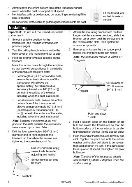
4 Drill the four screw holes 5/64" (2 mm)<br />
diameter and at right angles to the<br />
transom, so that when the screws are<br />
tightened the screw heads sit flat.<br />
Drill 5/64" (2 mm), apply<br />
sealant in holes (after<br />
adjusting and testing)<br />
Screw transducer onto<br />
transom<br />
5 Attach the mounting bracket with the four<br />
longer stainless screws provided, slide the<br />
bracket up or down until the screws are in<br />
the middle of the slots, then tighten the<br />
screws temporarily.<br />
6 If necessary, loosen the transducer pivot<br />
bolt so that the transducer can rotate.<br />
Note: the transducer rotates in ‘clicks’ of<br />
7 degrees.<br />
Parallel<br />
Fit the transducer<br />
so that its axis is<br />
vertical.<br />
1/4" (6 mm) or<br />
1/2" (12 mm) or<br />
3/4" (18 mm)<br />
Push end down<br />
1 click<br />
7 Hold a straight edge on the bottom of the<br />
hull and rotate the transducer so that the<br />
bottom surface of the transducer is parallel<br />
to the bottom of the hull (to the closest click).<br />
8 Push the end of the transducer down by one<br />
click. Tighten the pivot bolt until the rubber<br />
washer on the pivot bolt starts to compress,<br />
then add another 1/4 turn. If the transducer<br />
kicks up when at speed, then tighten the pivot<br />
bolt more.<br />
Note: The face of the transducer should<br />
face forward by about 7 degrees when the<br />
boat is moving.<br />
Pivot bolt<br />
4<br />
NAVMAN<br />
Transom Mount Transducers <strong>Installation</strong> <strong>Manual</strong>