EY-RC416, ecos416: DCC volume flow controller (7194115003)
EY-RC416, ecos416: DCC volume flow controller (7194115003)
EY-RC416, ecos416: DCC volume flow controller (7194115003)

You also want an ePaper? Increase the reach of your titles
YUMPU automatically turns print PDFs into web optimized ePapers that Google loves.
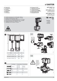
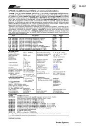
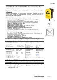
SAUTER <strong>EY</strong>-modulo 4<br />
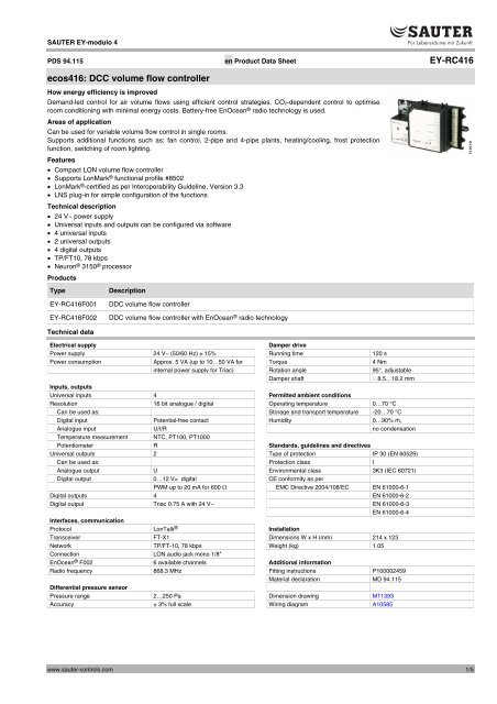
PDS 94.115 en Product Data Sheet <strong>EY</strong>-<strong>RC416</strong><br />
<strong>ecos416</strong>: <strong>DCC</strong> <strong>volume</strong> <strong>flow</strong> <strong>controller</strong><br />
How energy efficiency is improved<br />
Demand-led control for air <strong>volume</strong> <strong>flow</strong>s using efficient control strategies. CO2-dependent control to optimise<br />
room conditioning with minimal energy costs. Battery-free EnOcean ® radio technology is used.<br />
Areas of application<br />
Can be used for variable <strong>volume</strong> <strong>flow</strong> control in single rooms.<br />
Supports additional functions such as: fan control, 2-pipe and 4-pipe plants, heating/cooling, frost protection<br />
function, switching of room lighting.<br />
Features<br />
Compact LON <strong>volume</strong> <strong>flow</strong> <strong>controller</strong><br />
Supports LonMark ® functional profile #8502<br />
LonMark ® -certified as per Interoperability Guideline, Version 3.3<br />
LNS plug-in for simple configuration of the functions<br />
Technical description<br />
24 V~ power supply<br />
Universal inputs and outputs can be configured via software<br />
4 universal inputs<br />
2 universal outputs<br />
4 digital outputs<br />
TP/FT10, 78 kbps<br />
Neuron ® 3150 ® processor<br />
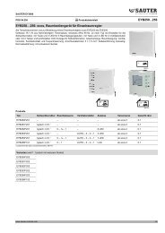
Products<br />
Type<br />
<strong>EY</strong>-<strong>RC416</strong>F001<br />
<strong>EY</strong>-<strong>RC416</strong>F002<br />
Description<br />
DDC <strong>volume</strong> <strong>flow</strong> <strong>controller</strong><br />
DDC <strong>volume</strong> <strong>flow</strong> <strong>controller</strong> with EnOcean ® radio technology<br />
Technical data<br />
Electrical supply<br />
Damper drive<br />
Power supply 24 V~ (50/60 Hz) ± 15% Running time 120 s<br />
Power consumption Approx. 5 VA (up to 10…50 VA for Torque 4 Nm<br />
internal power supply for Triac) Rotation angle 95°, adjustable<br />
Damper shaft<br />
8.5…18.2 mm<br />
Inputs, outputs<br />
Universal inputs 4 Permitted ambient conditions<br />
Resolution 16 bit analogue / digital Operating temperature 0…70 °C<br />
Can be used as: Storage and transport temperature -20…70 °C<br />
Digital input Potential-free contact Humidity 0…90% rh,<br />
Analogue input U/I/R no condensation<br />
Temperature measurement NTC, PT100, PT1000<br />
Potentiometer R Standards, guidelines and directives<br />
Universal outputs 2 Type of protection IP 30 (EN 60529)<br />
Can be used as: Protection class I<br />
Analogue output U Environmental class 3K3 (IEC 60721)<br />
Digital output 0…12 V= digital CE conformity as per<br />
PWM up to 20 mA for 600 EMC Directive 2004/108/EC EN 61000-6-1<br />
Digital outputs 4 EN 61000-6-2<br />
Digital output Triac 0.75 A with 24 V~ EN 61000-6-3<br />
EN 61000-6-4<br />
Interfaces, communication<br />
Protocol LonTalk ® Installation<br />
Transceiver FT-X1 Dimensions W x H (mm) 214 x 123<br />
Network TP/FT-10, 78 kbps Weight (kg) 1.05<br />
Connection LON audio jack mono 1/8"<br />
EnOcean ® F002 6 available channels Additional information<br />
Radio frequency 868.3 MHz Fitting instructions P100002459<br />
Material declaration MD 94.115<br />
Differential pressure sensor<br />
Pressure range 2…250 Pa Dimension drawing M11393<br />
Accuracy ± 3% full scale Wiring diagram A10585<br />
www.sauter-controls.com 1/5
<strong>EY</strong>-<strong>RC416</strong><br />
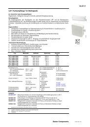
Accessories<br />
Type<br />
Description<br />
Manual operating panel<br />
<strong>EY</strong>-RU481F001<br />
<strong>EY</strong>-RU483F001<br />
<strong>EY</strong>-RU481F002<br />
<strong>EY</strong>-RU481F003<br />
Sensor<br />
Sensor-VAV, display<br />
Sensor, occupancy<br />
Sensor, occupancy, setpoint<br />
General functioning of the <strong>volume</strong> <strong>flow</strong> <strong>controller</strong><br />
The <strong>ecos416</strong> single-channel <strong>volume</strong> <strong>flow</strong> <strong>controller</strong> is a<br />
microprocessor-based, configurable <strong>volume</strong> <strong>flow</strong> <strong>controller</strong> used to<br />
control and regulate supply or return air <strong>volume</strong> <strong>flow</strong> boxes on the<br />
basis of LON ® technology. Individual, demand-led ventilation of<br />
individual rooms is possible in relation to the room occupancy, room<br />
temperature or the CO2 content of the air. The <strong>volume</strong> <strong>flow</strong> passing<br />
over the <strong>volume</strong> <strong>flow</strong> box is measured with an integrated static<br />
differential pressure sensor and is compared with the <strong>volume</strong> <strong>flow</strong><br />
setpoint specified by the <strong>controller</strong>. If the actual value deviates from<br />
the setpoint, the <strong>volume</strong> <strong>flow</strong> over the <strong>volume</strong> <strong>flow</strong> box is adjusted<br />
by means of the integrated damper drive until the required setpoint<br />
is attained. The inputs and outputs provided may be used for a<br />
variety of applications. The <strong>ecos416</strong> <strong>volume</strong> <strong>flow</strong> <strong>controller</strong> uses the<br />
LonTalk ® communication protocol and is LonMark ® -certified if the<br />
sensor profile (number 1) is used for the relevant input objects and<br />
if the actuator profile (number 3) is used for the relevant output<br />
objects. The <strong>ecos416</strong> intelligent unitary <strong>controller</strong> supports<br />
LonMark ® profile #8502, Space Comfort Controller - VAV.<br />
The integrated operating programme can be programmed freely<br />
with the help of a plug-in; it reads in the hardware and software<br />
addresses, processes the user programme, updates the outputs<br />
and handles the necessary communication with other stations in the<br />
network or with the management level. The user program can be<br />
loaded from any point in the LON ® network using<br />
SAUTER CASE LON Engine. The plug-ins can be used to<br />
parameterize the <strong>controller</strong>s with the SAUTER CASE LON Engine<br />
network management tool or via any LNS-based software,<br />
according to choice.<br />
Engineering notes<br />
Installation and wiring<br />
The <strong>volume</strong> <strong>flow</strong> <strong>controller</strong> can be fitted directly on the damper shaft<br />
of the <strong>volume</strong> <strong>flow</strong> box with the servo-motor. Another fixture on the<br />
housing of the <strong>volume</strong> <strong>flow</strong> <strong>controller</strong> functions as a counterbearing;<br />
this fixture is connected to the <strong>volume</strong> <strong>flow</strong> box.<br />
The plant devices are connected via screw terminals.<br />
The following conditions must be met:<br />
Cross-section<br />
conductors:<br />
LON network:<br />
of<br />
min. 0.82 mm 2 (AWG 18), max.<br />
2 mm² (AWG 13), compliant with<br />
standards and national installation<br />
regulations.<br />
min. 0.65 mm² (AWG 22), twisted and<br />
unscreened<br />
Suitable network terminations (terminators) must be used for<br />
different network topologies. Failure to comply with the specified<br />
requirements may cause transmission errors between the<br />
<strong>controller</strong>s. The use of different cable cross-sections in one network<br />
section is not permitted.<br />
Detailed guidelines on planning and installing twisted-pair<br />
LonWorks ® networks have been published by the Echolon ®<br />
Corporation.<br />
Connections:<br />
LON network: 2<br />
(Jack plug, mono, 1/8" / 3.5 mm)<br />
Earth terminals: 4<br />
I/O terminals: 10<br />
LS-MM terminals: 24 V~ ± 15%, 55 Hz<br />
300 mA (7.2 VA) with 24 V~<br />
Room operating unit: 2 (SMRT +/-)<br />
Hardware:<br />
The <strong>ecos416</strong> intelligent unitary <strong>controller</strong> comprises:<br />
Processor:<br />
Neuron ® 3150 ® ; 8 bit; 10 MHz<br />
Memory:<br />
Non-volatile 64 kB flash memory (APB<br />
application and programme)<br />
Communication: LonTalk ® protocol<br />
Channel:<br />
TP/FT-10, 78 kbps<br />
Status indicators: Green LED: Power supply status and<br />
LON-TX<br />
Orange LED: Operation and LON-RX<br />
Differential pressure<br />
sensor:<br />
Measuring range:<br />
Measurement<br />
accuracy:<br />
Damper drive:<br />
Torque:<br />
Running time for 90°:<br />
Static sensor with piezo-resistive<br />
recording of measured values<br />
2…250 Pa<br />
± 3% in relation to the entire<br />
measurement range (FS)<br />
Brushless DC<br />
4 Nm<br />
120 s<br />
Description of inputs and outputs<br />
The <strong>ecos416</strong> intelligent unitary <strong>controller</strong> has 4 universal inputs and<br />
2 universal outputs. 4 Triac outputs are also available. All the inputs<br />
and outputs must be configured via software. The input resolution is<br />
16 bits and the output resolution is 10 bits. The inputs and outputs<br />
may be used as follows:<br />
Input<br />
Temperature sensor:<br />
Potentiometer:<br />
Current:<br />
Voltage:<br />
Digital:<br />
Ni1000, NTC, Pt<br />
10 k, 100 k<br />
0…20 mA (4…20 mA)<br />
0…10 V<br />
Potential-free contact<br />
Output<br />
Voltage: 0…10 V=<br />
Digital:<br />
0…12 V= , (I/O)<br />
PWM<br />
The sampling period for the inputs is 1 s if they are configured as<br />
current, voltage, potentiometer or temperature inputs, and 500 ms<br />
for configuration as digital inputs. The UIx inputs can take a<br />
maximum load of 24 V.<br />
2/5 www.sauter-controls.com
<strong>EY</strong>-<strong>RC416</strong><br />
Technical specifications of inputs and outputs<br />
Temperature measurement (NTC, Pt)<br />
The Pt1000 sensors are connected using the two-wire method<br />
between one of the input terminals for a universal input<br />
(UI01…UI04) and an earth terminal. In case of an Ni/NTC/Pt<br />
connection, the inputs do not require calibration and can be used<br />
directly. The connected sensor type and the desired offset input are<br />
chosen in the software.<br />
NTC type 2, 10 k<br />
Range: -40…150 °C<br />
Accuracy: ± 0.5 °C<br />
NTC type 3, 10 k<br />
Range: -40…150 °C<br />
Accuracy: ± 0.5 °C<br />
Circuit Period duration Value<br />
Short-circuit/<br />
override *)<br />
< 5 s<br />
> 5 s<br />
> 15 s<br />
Override = on<br />
Override = off<br />
Input = +199.9<br />
Open - -199.9<br />
PT1000, 1 k<br />
Range: -40…150 °C<br />
Accuracy: ± 1 °C<br />
PT100, 100 k<br />
Range: -40…135 °C<br />
Accuracy: ± 1 °C<br />
Circuit Period duration Value<br />
Short-circuit/<br />
override *)<br />
< 5 s<br />
> 5 s<br />
> 15 s<br />
Override = on<br />
Override = off<br />
Input = +199.9<br />
Open - -199.9<br />
*) If the input is short-circuited, this may be interpreted as an override, i.e. the relevant<br />
control loop is switched from "unoccupied" status to the "occupied/override" operating<br />
mode.<br />
Potentiometer measurement (Pot)<br />
It is possible to use the input in combination with a potentiometer if<br />
a 10 k or 100 k resistance is used. For configuration purposes,<br />
the resistance value can be limited and scaled to any desired value<br />
range in °C. A potentiometer is connected between an input<br />
terminal of a universal input (UI01…UI04) and the associated earth<br />
terminal. The measurement accuracy is ± 0.5%.<br />
Current measurement (I)<br />
The current to be measured is connected to the input terminals of<br />
the universal inputs (UI01…UI04) between UIx and earth. The<br />
signal must be potential-free. In order to use the current input on<br />
the <strong>ecos416</strong> intelligent unitary <strong>controller</strong>, either a supply of current<br />
to the sensor or a parallel input-sensor supply is required. An<br />
external voltage source of 24 V= can be used for this purpose. A<br />
249 resistance must also be connected in parallel with the input.<br />
The input is defined as a 4…20mA input by default.<br />
Voltage measurement (U)<br />
The universal inputs (UI01…UI04) are used to measure voltage.<br />
The voltage input has a range of 0…10 V. The connection is made<br />
to an input and the associated earth terminal. The voltage signal<br />
must be potential-free. The input can be adapted to different ranges<br />
via software. Parameters "min.", "max." or "offset" are available for<br />
this purpose.<br />
Digital inputs (DI)<br />
All universal inputs (UI01…UI04) can be used as digital inputs and<br />
must be connected to earth.<br />
Type of inputs:<br />
Potential-free contacts, connected to earth<br />
Opto-coupler<br />
Transistor (open collector)<br />
Digital information is connected between the input terminals<br />
(UI01…UI04) and earth. The <strong>controller</strong> applies a voltage of approx.<br />
13 V to the terminal. In normal cases (NORMAL) this corresponds<br />
to INACTIVE (bit=0) for an open contact. When a contact is closed<br />
it is ACTIVE (bit=1) and 0 V is applied, whereby the current <strong>flow</strong><br />
equates to approx. 1 mA.<br />
For each input, it is possible to define the "on" and "off" values<br />
individually, as well as the direction of operation (normal or<br />
reverse).<br />
Universal outputs<br />
The universal outputs (UO05 and UO06) can be configured as<br />
voltage outputs, via the software. The output voltage is measured<br />
between the relevant output terminal and an earth terminal (UOx, 5-<br />
6).<br />
Type of output: 0…10 V=<br />
max. 60 mA to earth<br />
Digital output (DO)<br />
Alternatively, the universal outputs (UO05 and UO06) can be<br />
configured as digital outputs. A discrete output signal is issued: 0<br />
V= for OFF and 12 V= for ON.<br />
If a relay is triggered via the universal output, a diode (1N400x<br />
family) must be connected to the connection terminals in parallel.<br />
This protects the output against voltage peaks when the relay cuts<br />
out.<br />
If the universal outputs are configured as PWM outputs, the period<br />
duration can be set between 2 s and 15 min. The period duration<br />
can be set between 0 and 100% of the "on" duration.<br />
Loading capacity of the output: Max. 20 mA at 12 V=<br />
max. load 600 <br />
The output is fitted with a self-resetting fuse.<br />
Maximum power load: 60 mA at 60 °C<br />
100 mA at 100 °C<br />
Triac outputs<br />
4 Triac Max. 1.0 A at 24 V~ per Triac<br />
The jumpers on the <strong>controller</strong> must be changed over in order to use<br />
the internal 24 V supply.<br />
If the power supply is used internally, it is protected with a 3 A fuse.<br />
If the internal power supply is used, an AXT111F202 can be<br />
controlled via the 24 V output in combination with a Triac. For an<br />
application with two AXT111F202s for heating and cooling, it is only<br />
possible to operate one AXT111 in each load case. The internal<br />
heating-cooling sequence prevents the simultaneous operation of<br />
two AXT111F202s.<br />
www.sauter-controls.com 3/5
<strong>EY</strong>-<strong>RC416</strong><br />
Parameterisation of the intelligent unitary <strong>controller</strong>s<br />
Network variables<br />
The <strong>controller</strong> software supports structured SNVTs and UNVTs of 1<br />
and 2 bytes in length. 16 NVIs and 20 NVOs (with changeable<br />
types and lengths) are available.<br />
User programme<br />
Simple configuration of all device parameters, including inputs,<br />
outputs and setpoints for heating and cooling. It is also possible to<br />
parameterise additional integrated functions such as <strong>volume</strong> <strong>flow</strong><br />
calibration, CO2-led <strong>volume</strong> <strong>flow</strong> control, limit value alarms, load<br />
shedding, frost protection and slave operating mode.<br />
Support for EnOcean ® radio transmitters.<br />
The <strong>EY</strong>-<strong>RC416</strong>F002 intelligent unitary <strong>controller</strong> has an integrated<br />
EnOcean ® radio receiver. This ensures excellent compatibility with<br />
many wireless sensors and peripheral devices that are equipped<br />
with EnOcean ® technology.<br />
Receiver module:<br />
Reception range:<br />
EnOcean ® RCM120, 868.3 MHz<br />
10-30 m in buildings, approx. 300 m<br />
outdoors<br />
The EnOcean ® reception module allows the use of up to 5 wireless<br />
sensors for room temperature, channel temperature or humidity.<br />
Window and door contacts as well as light switches are supported<br />
with up to 4 channels.<br />
Functional profile<br />
nviRequest<br />
SNVT_obj_request<br />
<strong>ecos416</strong> Node<br />
Object Type #0<br />
Mandatory<br />
Network<br />
Variables<br />
Optional<br />
Network<br />
Variables<br />
Configuration Properties<br />
Device Major Version (optional)<br />
Device Minor Version (optional)<br />
Location (optional)<br />
Maximum Send Time (optional)<br />
Manufacturer<br />
Network<br />
Variables<br />
Manufacturer Configuration Properties<br />
Hardware Information<br />
nvoStatus<br />
SNVT_obj_status<br />
nvoFileDirectory<br />
SNVT_address<br />
nvoVAVstate<br />
SNVT_state_64<br />
nvoVAValarm<br />
SNVT_state_64<br />
nviSpaceTemp<br />
SNVT_temp_p<br />
nviAirFlow<br />
SNVT_<strong>flow</strong><br />
nviApplicMode<br />
SNVT_hvac_mode<br />
nviCO2<br />
SNVT_ppm<br />
nviEmergOverride<br />
SNVT_hvac_emerg<br />
nviFlowOverride<br />
SNVT_hvac_overid<br />
nviOccManCmd<br />
SNVT_occupancy<br />
<strong>ecos416</strong> VAV<br />
Object Type #8502<br />
Mandatory<br />
Network<br />
Variables<br />
Optional<br />
Network<br />
Variables<br />
nvoSpaceTemp<br />
SNVT_temp_p<br />
nvoUnitStatus<br />
SNVT_hvac_status<br />
nvoAirFlow<br />
SNVT_<strong>flow</strong><br />
nvoEffectOccup<br />
SNVT_occupancy<br />
nvoEffectSetpt<br />
SNVT_temp_p<br />
nvoFlowSetpoint<br />
SNVT_<strong>flow</strong><br />
nvoTerminalLoad<br />
SNVT_lev_percent<br />
nviHwOutputx (x=1-6)<br />
SNVT_switch<br />
<strong>ecos416</strong> Hardware Input<br />
Object Type #1<br />
Mandatory<br />
Network<br />
Variables<br />
Configuration Properties<br />
Maximum Range (optional)<br />
Minimum Range (optional)<br />
Minimum Send Delta (optional)<br />
Maximum Send Time (optional)<br />
Minimum Send Time (optional)<br />
Override Value (optional)<br />
Manufacturer Configuration Properties<br />
Default Value<br />
Hardware Properties<br />
Input Signal Conditioning<br />
Object Major Version<br />
Object Minor Version<br />
Offset<br />
Translation Table<br />
<strong>ecos416</strong> Hardware Output<br />
Object Type #1<br />
Mandatory<br />
Network<br />
Variables<br />
Configuration Properties<br />
Maximum Receive Time (optional)<br />
Override Value (optional)<br />
Manufacturer Configuration Properties<br />
Default Value<br />
Hardware Properties<br />
Maximum Range<br />
Minimum Range<br />
Object Major Version<br />
Object Minor Version<br />
Output Signal Conditioning<br />
PWM Period<br />
nvoHwInputx (x=1-4)<br />
SNVT_temp_f<br />
(changeable)<br />
nviOutdoorTemp<br />
SNVT_temp_p<br />
nviSetPoint<br />
SNVT_temp_p<br />
nviSetptOffset<br />
SNVT_temp_p<br />
nviWaterTemp<br />
SNVT_temp_p<br />
nviCalibCode<br />
SNVT_str_16<br />
nviDuctInTemp<br />
SNVT_temp_p<br />
nviFlowCalib<br />
UNVT_<strong>flow</strong>_calib<br />
nviHotAir<br />
SNVT_switch<br />
nviHotWater<br />
SNVT_switch<br />
nviOccCmd<br />
SNVT_occupancy<br />
nviShedding<br />
SNVT_switch<br />
nviSlave<br />
SNVT_lev_percent<br />
nviVAVinfo<br />
SNVT_str_asc<br />
(changeable)<br />
Configuration Properties<br />
Temperature Set Points (mandatory)<br />
ECC-VAV Send Heartbeat SCC-VAV (mandatory) Controller<br />
Bypass Time (optional)<br />
Object Type #8502<br />
Duct Area (optional)<br />
Maximum Flow (optional)<br />
Minimum Flow (optional)<br />
Minimum Flow for Heating (optional)<br />
Minimum Send Time (optional)<br />
Nominal Flow (optional)<br />
Receive Heartbeat (optional)<br />
Space CO Limit (optional)<br />
2<br />
Manufacturer<br />
Network<br />
Variables<br />
nvoComInputs<br />
UNVT_gen_values<br />
nvoCtrlOut1<br />
SNVT_switch<br />
.<br />
.<br />
.<br />
nvoCtrlOut6<br />
SNVT_switch<br />
nvoCtrlStatus<br />
UNVT_8_ctrl_status<br />
nvoDamperPos<br />
SNVT_lev_percent<br />
nvoOccState<br />
SNVT_occupancy<br />
nvoRoomInfo<br />
UNVT_2room_info<br />
nvoVAVinfo<br />
SNVT_str_asc<br />
Manufacturer Configuration Properties<br />
Please refer to the list of UCPTs in the User Guide<br />
The Manufacturer CPs are configurable using the<br />
device plug-in<br />
4/5 www.sauter-controls.com
<strong>EY</strong>-<strong>RC416</strong><br />
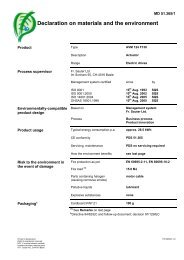
Dimension drawing<br />
60<br />
21<br />
65<br />
33<br />
182<br />
36<br />
123<br />
125<br />
19<br />
15<br />
17<br />
M11393<br />
Wiring diagram<br />
12VDC Relay<br />
Uxx0-10V<br />
Triac DOx<br />
┴ x-x Fuse<br />
Ext. Trafo 230 / 24 V<br />
+<br />
Triac DOx<br />
┴ x-x<br />
Triac DOx<br />
Fuse<br />
+<br />
L<br />
N<br />
2-Line Main<br />
AXT111F202<br />
1 2<br />
1 2 3<br />
1 2 3 4 5 6<br />
MM LS<br />
24 V AC<br />
UO5<br />
5-6<br />
UO6<br />
DO1<br />
1-2<br />
DO2<br />
DO3<br />
3-4<br />
DO4<br />
Outputs (Universal)<br />
Power<br />
Service<br />
<strong>ecos416</strong><br />
Inputs (Universal)<br />
InternalPowerSupply ExternalPowerSupply<br />
Outputs (Triac)<br />
ecoUnit 483<br />
TX<br />
RX<br />
UI 1<br />
UI 2<br />
1-2-3-4<br />
UI 3<br />
UI 4<br />
p<br />
2...250Pa<br />
SMRT+<br />
SMRT -<br />
LON1<br />
LON2<br />
01 02 03 04 05<br />
HIGH<br />
LOW<br />
1 2 1 2<br />
A10585<br />
249 <br />
NTC 10k<br />
Pt100<br />
0...10 V 10 k 4...20 mA<br />
Platin 1k-RTD<br />
Digitaler Eingang<br />
Digital Input<br />
Entrée digitales<br />
© Fr. Sauter Ltd<br />
Im Surinam 55<br />
CH-4016 Basle<br />
Tel. +41 61 - 695 55 55<br />
Fax +41 61 - 695 55 10<br />
www.sauter-controls.com<br />
info@sauter-controls.com<br />
www.sauter-controls.com <strong>7194115003</strong>5/5<br />
01<br />
Printed in Switzerland