Fluid flow and heat transfer simulation in a - SIMS - Scandinavian ...
Fluid flow and heat transfer simulation in a - SIMS - Scandinavian ...
Fluid flow and heat transfer simulation in a - SIMS - Scandinavian ...

You also want an ePaper? Increase the reach of your titles
YUMPU automatically turns print PDFs into web optimized ePapers that Google loves.
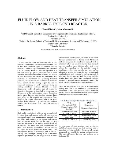
FLUID FLOW AND HEAT TRANSFER SIMULATION<br />
IN A BARREL TYPE CVD REACTOR<br />
Hamid Nabati 1 , Jafar Mahmoudi 2<br />
1 PhD Student, School of Susta<strong>in</strong>able Development of Society <strong>and</strong> Technology (HST),<br />
Mälardalen University<br />
Västerås, Sweden<br />
2 Adjunct Professor, School of Susta<strong>in</strong>able Development of Society <strong>and</strong> Technology (HST),<br />
Mälardalen University<br />
Västerås, Sweden<br />
hamid.nabati@mdh.se (Hamid Nabati)<br />
Abstract<br />
Th<strong>in</strong>-film coat<strong>in</strong>g plays an important role <strong>in</strong> the<br />
manufactur<strong>in</strong>g of many cutt<strong>in</strong>g <strong>and</strong> drill<strong>in</strong>g tools. One<br />
of the most common types of th<strong>in</strong>-film coat<strong>in</strong>g<br />
methods is chemical vapor deposition that is known as<br />
CVD <strong>in</strong> <strong>in</strong>dustry. The CVD <strong>in</strong>volves deposition of a<br />
th<strong>in</strong> film from gas phase precursors onto a solid<br />
substrate. The uniformity of film thickness is a critical<br />
<strong>in</strong> tools production. To achieve this uniformity, it is<br />
necessary to underst<strong>and</strong> the govern<strong>in</strong>g transport<br />
processes, <strong>flow</strong> behavior <strong>and</strong> <strong>heat</strong> <strong>transfer</strong> <strong>in</strong>side the<br />
CVD reactor. In the com<strong>in</strong>g paper the aim is<br />
numerical model<strong>in</strong>g of CVD processes us<strong>in</strong>g an<br />
exist<strong>in</strong>g <strong>simulation</strong> software, Fluent©. A three<br />
dimensional model of active part of reactor is<br />
simulated. Geometry is simplified to concentrate on<br />
<strong>flow</strong> regime <strong>in</strong> the whole solution doma<strong>in</strong>. Simulation<br />
results show that the gases feed<strong>in</strong>g entrances have<br />
greet effect on the velocity <strong>and</strong> temperature field.<br />
Based on the results, it is recommended to use same<br />
feed<strong>in</strong>g holes diameters to achieve the uniform<br />
velocity <strong>and</strong> temperature field <strong>in</strong>side the coat<strong>in</strong>g<br />
doma<strong>in</strong>.<br />
1 Introduction<br />
High quality mach<strong>in</strong><strong>in</strong>g is achieved <strong>and</strong> accomplished<br />
by us<strong>in</strong>g high grade cutt<strong>in</strong>g tools. All manufacturers<br />
cont<strong>in</strong>uously apply new manufactur<strong>in</strong>g materials that<br />
are lighter <strong>and</strong> stronger, so the cutt<strong>in</strong>g tool makers<br />
have to develop tools that can be used for new<br />
materials mach<strong>in</strong><strong>in</strong>g at the highest possible levels of<br />
productivity. To atta<strong>in</strong> this goal, comb<strong>in</strong>ations of<br />
better tool material compositions, modern coat<strong>in</strong>g<br />
techniques <strong>and</strong> novel geometries are necessary. This<br />
development process is cont<strong>in</strong>uous <strong>and</strong> <strong>in</strong>teractive.<br />
Among these challenges, coat<strong>in</strong>g is one of the most<br />
important parameters that has major effects on tools<br />
characteristics like toughness, resistance to oxidation,<br />
hardness <strong>and</strong> resistance to thermal shock. Most steels<br />
<strong>and</strong> cast irons, <strong>and</strong> also non-ferrous materials such as<br />
alum<strong>in</strong>um alloys are easier to mach<strong>in</strong>e than materials<br />
such as sta<strong>in</strong>less steels, titanium alloys <strong>and</strong> superalloys.<br />
So depend<strong>in</strong>g on the material which is<br />
mach<strong>in</strong>ed, a given tool material may not perform<br />
adequately unless its properties are strengthened.<br />
Application of hard coat<strong>in</strong>gs by various methods is<br />
also used for this purpose. Both s<strong>in</strong>gle <strong>and</strong> multiplecoat<strong>in</strong>g<br />
have been shown that significantly enhance<br />
any tool<strong>in</strong>g material, but this is a complex subject that<br />
needs careful design to achieve high performance.<br />
There are basically two techniques of hard coat<strong>in</strong>g for<br />
cutt<strong>in</strong>g tools used <strong>in</strong> the <strong>in</strong>dustry[1]: chemical vapor<br />
deposition (CVD) <strong>and</strong> physical vapor deposition<br />
(PVD). Each of these methods <strong>in</strong>cludes several special<br />
techniques that are summarized <strong>in</strong> Tab. 1.<br />
Tab. 1 Hard coat<strong>in</strong>g techniques for cutt<strong>in</strong>g tools [1]<br />
CVD<br />
PVD<br />
Conventional CVD Evaporation<br />
Plasma Assisted CVD<br />
(PACVD)<br />
Magnetron Sputter<strong>in</strong>g<br />
Medium Temperature<br />
CVD (MTCVD))<br />
Ion Beam Assisted<br />
Deposition (IBAD<br />
Metal-Organic CVD<br />
(MOCVD)<br />
Hybrid PVD, Pulsed<br />
Plasma PVD<br />
Laser CVD (LCVD) Laser PVD (LPVD)<br />
A wide range of hard coat<strong>in</strong>gs, such as nitrides,<br />
carbides, borides, oxides <strong>and</strong> their mixtures can be<br />
deposited by both methods. However, only certa<strong>in</strong><br />
compounds are suitable for cutt<strong>in</strong>g tool applications.<br />
The ma<strong>in</strong> differences between two methods are as<br />
follow<strong>in</strong>g [2]:
• The PVD process is run at lower temperatures<br />
(180 o C to 500 o C) that mean that nearly all tool<br />
materials can be coated without concern for<br />
soften<strong>in</strong>g or deformation. This process does not<br />
utilize any harmful materials which makes it<br />
environmentally friendly. The PVD process is<br />
also very energy efficient <strong>and</strong> it ensures excellent<br />
adhesion.<br />
• The CVD is a high temperature process with<br />
typical coat<strong>in</strong>g temperature around 1000 o C that<br />
is used widely <strong>in</strong> applications requir<strong>in</strong>g<br />
resistance to erosion, wear <strong>and</strong> corrosion over an<br />
extensive range of temperatures. The chemical<br />
bond that is produced between the coat<strong>in</strong>g <strong>and</strong><br />
substrate, results <strong>in</strong> excellent diffusion. All<br />
surfaces <strong>in</strong>clud<strong>in</strong>g niche areas <strong>and</strong> shaded holes<br />
are reliably coated. Also thick coat<strong>in</strong>gs can be<br />
deposited for heavy wear applications.<br />
The CVD method which has been considered for<br />
current study generally uses a gas-phase precursor.<br />
This precursor is usually a halide or hydride of the<br />
element that be<strong>in</strong>g deposited. A typical coat<strong>in</strong>g system<br />
is <strong>in</strong>cluded an electrical <strong>heat</strong>ed furnace; a reaction<br />
chamber, special fixtures us<strong>in</strong>g for the parts to be<br />
coated, a vacuum system with a halide gas generator<br />
<strong>and</strong> gas delivery system that are used for alum<strong>in</strong>um<br />
oxide process, smog neutralization system (or<br />
scrubber). These subsystems are controlled by an<br />
automated control system[3]. A description of CVD<br />
process is presented <strong>in</strong> section 2.<br />
There are few attempt<strong>in</strong>g <strong>in</strong> numerical <strong>simulation</strong> of<br />
CVD reactors. Duverneuil & Couderc[4] <strong>and</strong> also<br />
Moffat[5] have <strong>in</strong>vestigated on numerical results for<br />
<strong>flow</strong> field <strong>in</strong> a realistic CVD geometry <strong>in</strong> two<br />
dimensions. In another study, Park & Pak [6] have<br />
worked on the <strong>flow</strong>, <strong>heat</strong> <strong>and</strong> mass <strong>transfer</strong> <strong>in</strong> a CVD<br />
reactor that its configuration is different from what<br />
considered <strong>in</strong> the present study. Kazunori <strong>and</strong><br />
coworkers performed numerical <strong>simulation</strong> to model<br />
the <strong>heat</strong> <strong>and</strong> mass <strong>transfer</strong> process that takes place<br />
dur<strong>in</strong>g the growth of CNTs <strong>in</strong> a CVD reactor. They<br />
found that substrate located <strong>in</strong>side the reactor causes<br />
irregular <strong>flow</strong> field. Based their results, they suggested<br />
a new geometry for the reactor [7]. Lu <strong>and</strong> coworkers<br />
simulated the effects of temperature, pressure,<br />
concentration of gas, <strong>and</strong> <strong>in</strong>let velocity of gas mixture<br />
on the composition of coat<strong>in</strong>g <strong>and</strong> rate of coat<strong>in</strong>g<br />
growth <strong>in</strong> a tubular CVD reactor [8].<br />
In this paper a thermal CVD reactor is analyzed<br />
numerically. The work is focused on the thermal <strong>and</strong><br />
<strong>flow</strong> fields around the multiple substrates <strong>in</strong>side the<br />
reactor. The space between the tools trays is<br />
considered as the solution doma<strong>in</strong> <strong>and</strong> a series of<br />
numerical analyses have been performed to atta<strong>in</strong> a<br />
reliable solution. The grid <strong>in</strong>dependency is checked<br />
severely to ensure about f<strong>in</strong>al results.<br />
2 Process specifications<br />
The <strong>simulation</strong> presented <strong>in</strong> this paper is focus<strong>in</strong>g on<br />
multiple-coat<strong>in</strong>g CVD process tak<strong>in</strong>g place <strong>in</strong> a<br />
vertical CVD reactor with a rotat<strong>in</strong>g susceptor. The<br />
ma<strong>in</strong> material for <strong>in</strong>sert body is cemented carbides<br />
(WC/CO). This material is produced by special<br />
powder metallurgy methods, lump<strong>in</strong>g gra<strong>in</strong>s of WC<br />
(tungsten carbide) <strong>in</strong> a Co (cobalt) matrix which<br />
provides toughness property. Coat<strong>in</strong>g consists of three<br />
different layers: First a layer consist<strong>in</strong>g of titanium<br />
carbide (TiC) <strong>and</strong> titanium nitride (TiN) which is<br />
referred as Ti(C, N). The second layer is alum<strong>in</strong>um<br />
oxide (Al 2 O 3 ) <strong>and</strong> the last layer which covers the<br />
<strong>in</strong>sert is TiN. Inserts that are go<strong>in</strong>g to be coated are<br />
placed <strong>in</strong> a hydrogen reduc<strong>in</strong>g atmosphere react<strong>in</strong>g<br />
chamber with a pressure about 10% of atmospheric<br />
pressure. Gases that are conta<strong>in</strong><strong>in</strong>g the coat<strong>in</strong>g<br />
elements are <strong>in</strong>troduced to the atmosphere <strong>and</strong><br />
circulated through the reaction chamber <strong>and</strong> over the<br />
<strong>in</strong>serts.<br />
The coat<strong>in</strong>gs are formed on the surfaces of the <strong>in</strong>serts,<br />
by chemical reactions between the gases. Typical<br />
temperature for the formation of TiC, TiN <strong>and</strong> Al2O3<br />
on the surfaces of cemented carbides is about 1000°C.<br />
The reactions that lead to the coat<strong>in</strong>gs are shown <strong>in</strong><br />
Eq. 1 to Eq. 3.<br />
2 2 <br />
2 8 (1)<br />
2 3 3 s<br />
6 3 (2)<br />
4 2 <br />
2 8(g) (3)<br />
The total coat<strong>in</strong>g thickness is about 5-20µm. A typical<br />
photo of coat<strong>in</strong>g layers produced by CVD process is<br />
also shown <strong>in</strong> Fig. 1. Schematic representation of<br />
CVD coat<strong>in</strong>g process is presented <strong>in</strong> Fig. 2Fig. 9.<br />
TiN<br />
Al 2 O 3<br />
TiCN<br />
Substrate<br />
WC/Co<br />
Fig. 1 Typical coat<strong>in</strong>g layer <strong>in</strong> CVD process
Fig. 2 Schematic of CVD coat<strong>in</strong>g process [2]<br />
The reactor chamber consists of a ma<strong>in</strong> cyl<strong>in</strong>drical<br />
chamber, a circular <strong>in</strong>let section, <strong>and</strong> a circular outlet<br />
section. Inserts to be coated placed on trays <strong>and</strong> these<br />
tool trays (Fig. 3) are precisely placed one above<br />
another <strong>and</strong> then loaded onto a central gas distribution<br />
column. This column is placed <strong>in</strong>side circular <strong>in</strong>let<br />
section. The reaction chamber is <strong>heat</strong>ed by an<br />
electrical furnace <strong>in</strong> an <strong>in</strong>ert atmosphere until the<br />
coat<strong>in</strong>g temperature (1000°C) is reached. An actual<br />
photo of reactor chamber <strong>in</strong> hot condition is shown <strong>in</strong><br />
Fig. 4 while the electrical furnace is moved up.<br />
The coat<strong>in</strong>g cycle is <strong>in</strong>itiated by the <strong>in</strong>troduction of<br />
TiCl 4 (Titanium tetrachloride) together with CH4<br />
(Methane) <strong>and</strong> Nitrogen (N 2 ) <strong>in</strong>to the reactor. The<br />
TiCl 4 is a cloud of unstable <strong>and</strong> volatile vapour, so it<br />
is transported <strong>in</strong>to the reactor by hydrogen (H 2 ) as<br />
carrier gas. This gases mixture reacts on the hot <strong>in</strong>serts<br />
surfaces <strong>and</strong> the chemical reaction forms the first<br />
coat<strong>in</strong>g layer (TiCN). Resulted gases (HCl <strong>and</strong> H 2 ) are<br />
discharged <strong>and</strong> other gases that are required for<br />
follow<strong>in</strong>g layers are <strong>in</strong>troduced respectively. The<br />
whole process takes place <strong>in</strong> one cycle tak<strong>in</strong>g<br />
approximately 14 hours (<strong>in</strong>clud<strong>in</strong>g <strong>heat</strong><strong>in</strong>g up, coat<strong>in</strong>g<br />
<strong>and</strong> cool<strong>in</strong>g down).<br />
Experimental measurements have been showed that<br />
the coat<strong>in</strong>g thickness varies <strong>in</strong>versely with radius<br />
distance from gas distribution column at the current<br />
configuration of CVD reactor which affects the<br />
coat<strong>in</strong>g uniformity for <strong>in</strong>serts. The <strong>in</strong>serts those are<br />
closer to the tools trays center have less coat<strong>in</strong>g<br />
thickness than <strong>in</strong>serts that are far from center (Fig. 5).<br />
This means that the coat<strong>in</strong>g uniformity should be<br />
studied consider<strong>in</strong>g this parameter beside the other<br />
affect<strong>in</strong>g parameters. The thickness of the coat<strong>in</strong>g<br />
layer is a basically function of various gaseous<br />
constituents <strong>and</strong> their relevant <strong>flow</strong> rates, coat<strong>in</strong>g<br />
temperature <strong>and</strong> the soak<strong>in</strong>g time at this temperature.<br />
However velocity profile <strong>and</strong> <strong>flow</strong> field <strong>in</strong>side the<br />
reactor are parameters that effect on the particles<br />
distribution <strong>and</strong> residence time <strong>and</strong> consequently on<br />
the coat<strong>in</strong>g thickness uniformity.<br />
Coat<strong>in</strong>g thickness<br />
Tray radius<br />
Fig. 3 Tools tray loaded with <strong>in</strong>serts(SecoTools Co.)<br />
Fig. 5 Coat<strong>in</strong>g thickness versos distance from tool tray<br />
center<br />
3 Numerical <strong>simulation</strong><br />
Govern<strong>in</strong>g equations for the problem are cont<strong>in</strong>uity<br />
equation, general transport equation <strong>and</strong> energy<br />
equation that are solved us<strong>in</strong>g Fluent software. The<br />
cont<strong>in</strong>uity equation is applicable for both<br />
<strong>in</strong>compressible <strong>and</strong> compressible <strong>flow</strong>s consider<strong>in</strong>g<br />
one cont<strong>in</strong>uous phase without any or phase change<br />
<strong>and</strong> chemical reaction [9].<br />
<br />
<br />
<br />
<br />
<br />
0 (4)<br />
General transport equation is stated as follow<strong>in</strong>g:<br />
Fig. 4 Reactor chamber for CVD process<br />
<br />
<br />
<br />
<br />
<br />
<br />
Γ <br />
<br />
<br />
(5)
The first term on the left side represent the rate of<br />
transport property (φ) storage <strong>in</strong> the control volume.<br />
The second term <strong>in</strong> left h<strong>and</strong> st<strong>and</strong>s for the net flux of<br />
φ due to convection from the control volume. The first<br />
<strong>and</strong> second terms on the right h<strong>and</strong> side represent<br />
respectively net flux of φ due to diffusion <strong>in</strong>to the<br />
control volume <strong>and</strong> net rate of creation of φ <strong>in</strong>side the<br />
control volume. Eq. (5) then exp<strong>and</strong>s for momentum<br />
equations, energy equat<strong>in</strong>g <strong>and</strong> also turbulence model<br />
(like st<strong>and</strong>ard k-ε).<br />
Built-<strong>in</strong> discretisation method <strong>in</strong>cluded <strong>in</strong> Fluent is<br />
used to treat the above transport equations. The Active<br />
part of CVD reactor modeled <strong>in</strong> Fluent is shown <strong>in</strong><br />
Fig. 6. The solution doma<strong>in</strong> consists of 450630 cells.<br />
A segregated solver is used for <strong>simulation</strong> that<br />
employs the f<strong>in</strong>ite volume of discretization process.<br />
The govern<strong>in</strong>g equations are solved sequentially. As<br />
these equations are <strong>in</strong>herently nonl<strong>in</strong>ear, several<br />
iterations loop should be performed before a<br />
converged solution is obta<strong>in</strong>ed. Second order upw<strong>in</strong>d<br />
solution is applied for momentum equation, turbulent<br />
k<strong>in</strong>etic energy, turbulent dissipation <strong>and</strong> energy<br />
equation. Based on available data, “pressure <strong>in</strong>let”,<br />
“pressure outlet” is assumed. The pressure outlet is<br />
used to def<strong>in</strong>e static pressure at <strong>flow</strong> outlets. Density<br />
<strong>and</strong> viscosity of gases is a function of temperature <strong>and</strong><br />
pressure. As the temperature levels are high, these<br />
effects are considered for <strong>simulation</strong>. To <strong>in</strong>vestigate<br />
the thermal performance of reactor, the energy<br />
equation is solved. However, energy of chemical<br />
reaction, volumetric <strong>heat</strong> generation, species diffusion<br />
<strong>and</strong> viscous dissipation terms are not considered <strong>in</strong> the<br />
energy equation. Also the steady state condition is<br />
adopted for model<strong>in</strong>g.<br />
entrance has smaller diameter respect to the right side<br />
one (d left /d right = 0.6). The left side of the model has<br />
higher temperature level that means <strong>in</strong>serts <strong>in</strong> this<br />
region placed <strong>in</strong> the more adequate temperature range<br />
than the <strong>in</strong>serts which are located <strong>in</strong> the right part. As<br />
it was expla<strong>in</strong>ed <strong>in</strong> the process specification, typical<br />
temperature for the formation of different coat<strong>in</strong>g<br />
layers on the surfaces of cemented carbides is about<br />
1000°C. So the best regions <strong>in</strong>side the active part are<br />
places with a temperature profile as close as this<br />
value. Contour of total temperature <strong>in</strong> a vertical<br />
surface is also illustrated <strong>in</strong> Fig. 8. Along the height of<br />
rector, aga<strong>in</strong> the temperate levels are higher at the left<br />
side. Also <strong>in</strong> the whole doma<strong>in</strong> the temperature is<br />
higher at the upper parts. This also can results <strong>in</strong><br />
different coat<strong>in</strong>g characteristics <strong>in</strong> the bottom <strong>and</strong> top<br />
of <strong>in</strong>serts. It should be noticed that the illustrated<br />
model is repeated <strong>in</strong> a real reactor. In fact, there are<br />
more than 30 numbers of this model that are precisely<br />
placed one above another <strong>and</strong> then loaded onto a<br />
central gas distribution column. The bottom of this<br />
model represent the top of <strong>in</strong>serts <strong>and</strong> the <strong>in</strong>side<br />
section of its roof represents the bottom of <strong>in</strong>serts that<br />
are plac<strong>in</strong>g <strong>in</strong> the next part of CVD reactor.<br />
Fig. 7 Contour of total temperature (K) <strong>in</strong> horizontal<br />
surface<br />
Fig. 6 Active part of coat<strong>in</strong>g <strong>in</strong>side the reactor<br />
4 Results <strong>and</strong> discussion<br />
Distribution of temperature, velocity magnitude <strong>and</strong><br />
vectors resulted from numerical solution are presented<br />
<strong>in</strong> the Fig. 7 to Fig. 11.<br />
Fig. 7 shows the temperature distribution a horizontal<br />
surface close to <strong>in</strong>let passages. Effect of entrance<br />
holes diameters is obvious from the figure. The left<br />
Fig. 8 Contour of total temperature (K) <strong>in</strong> vertical<br />
surface
Fig. 9 illustrates the temperature contour <strong>in</strong> top <strong>and</strong><br />
bottom surfaces. Follow<strong>in</strong>g the above discussion, it<br />
confirms that temperature distribution <strong>in</strong> top <strong>and</strong><br />
bottom are different. It means that the up <strong>and</strong> bottom<br />
surface of <strong>in</strong>serts can have different coat<strong>in</strong>g thickness,<br />
as they face to different thermal condition through the<br />
process. Look<strong>in</strong>g to the entrance section, it is seen that<br />
the temperature gradient is high. So this is not a good<br />
location to place the <strong>in</strong>serts dur<strong>in</strong>g the coat<strong>in</strong>g<br />
process. This is the case aga<strong>in</strong>, when we get close to<br />
outer edges, where there exists large temperature<br />
gradient.<br />
A better illustration of velocity distribution among the<br />
radius is shown <strong>in</strong> Fig. 11. It is clear that the left side<br />
has a more uniform temperature distribution. Also<br />
aga<strong>in</strong> it shows that it’s better to place the <strong>in</strong>serts <strong>in</strong> the<br />
middle section of the tools tray.<br />
Fig. 11 Velocity magnitude along the vertical plane<br />
(m/s)<br />
Simulation results declare that for current runn<strong>in</strong>g<br />
conditions, a distribution column with smaller holes<br />
perform better. So one design improvement can be<br />
change of current distribution column with a new one<br />
conta<strong>in</strong><strong>in</strong>g smaller drilled holes.<br />
Fig. 9 Contour of total temperature (K) <strong>in</strong> upper <strong>and</strong><br />
lower surfaces<br />
Velocity vectors are shown <strong>in</strong> Fig. 10. There is<br />
relatively uniform velocity distribution through the<br />
doma<strong>in</strong> except for regions close to right side edge <strong>and</strong><br />
also locations that are <strong>in</strong> front of entrance holes. The<br />
uniformity it more better <strong>in</strong> the left side. High<br />
velocities causes decrease <strong>in</strong> residence time of gases<br />
mixture <strong>in</strong> the reactor <strong>and</strong> subsequently results <strong>in</strong><br />
decrease <strong>in</strong> coat<strong>in</strong>g thickness <strong>in</strong> high velocity regions.<br />
5 Conclusion<br />
The <strong>flow</strong> regime <strong>and</strong> <strong>heat</strong> <strong>transfer</strong> was studied<br />
numerically for the tools tray <strong>in</strong>stalled <strong>in</strong> a CVD<br />
reactor with respect to diameters of gas feed<strong>in</strong>g holes<br />
<strong>in</strong> the distribution column. The follow<strong>in</strong>g results were<br />
obta<strong>in</strong>ed:<br />
1) The smaller diameter causes the more uniform<br />
temperature distribution over the tools tray.<br />
2) At current configuration of tools tray <strong>and</strong> reactor,<br />
the best place for <strong>in</strong>serts arrangement is the middle<br />
part of tray. It’s better to avoid plac<strong>in</strong>g the <strong>in</strong>serts <strong>in</strong><br />
region close to distribution column <strong>and</strong> also to edges<br />
of the active part.<br />
3) The temperature gradient is much higher than the<br />
velocity. Velocity gradient gets sharp <strong>in</strong> region close<br />
to edges <strong>and</strong> also <strong>in</strong> the way straight <strong>in</strong> front of<br />
feed<strong>in</strong>g holes.<br />
4) The top side of the <strong>in</strong>serts could have different<br />
coat<strong>in</strong>g parameters than the bottom side, as the<br />
temperature profiles are different <strong>in</strong> the ceil <strong>and</strong> floor<br />
of the active part.<br />
Fig. 10 Velocity vector colored by velocity magnitude<br />
(m/s)<br />
5) Average temperature of space over the tools tray is<br />
less than the amount which is required for efficient<br />
coat<strong>in</strong>g process. It means that to achieve the optimal<br />
coat<strong>in</strong>g reactions, it is better to <strong>in</strong>crease the<br />
temperature of thermal energy source.
This approach to th<strong>in</strong>-film manufactur<strong>in</strong>g control<br />
opens the door to a new generation of CVD reactor<br />
designs, allow<strong>in</strong>g precise thickness uniformity control<br />
<strong>in</strong> a s<strong>in</strong>gle reactor design. The numerical results offer<br />
the possibility of develop<strong>in</strong>g CVD reactors with more<br />
uniform thickness coat<strong>in</strong>g with low <strong>in</strong>vestment.<br />
6 Acknowledgments<br />
We would like to acknowledge the use of Fluent Inc.'S<br />
solver Fluent 6.2, <strong>and</strong> its mesh generator Gambit <strong>in</strong><br />
the current work. The authors also would like to<br />
acknowledge technical office staff <strong>in</strong> SecoTools<br />
Company, for their technical support <strong>and</strong> guides.<br />
7 References<br />
[1] Deepak, Bhat G., Application of CVD <strong>and</strong> PVD<br />
technologies to cutt<strong>in</strong>g tools <strong>and</strong> evaluation of tool<br />
failure modes., Revista de la facultad de<br />
<strong>in</strong>geniería, Vol. 13-N2, p. 15, 1998<br />
[2] Graham, Smith T., Cutt<strong>in</strong>ng tool technology,<br />
Eng<strong>in</strong>eer<strong>in</strong>g h<strong>and</strong>book, Spr<strong>in</strong>ger-Verlag London<br />
Limited, 2008.<br />
[3] http://www.hi-techfurnace.com.<br />
[4] Duverneuil, P. <strong>and</strong> Couderc, J-P.,Two dimensional<br />
model<strong>in</strong>g of low pressure chemical vapour<br />
deposition hot wall tubular reactors, Journal of<br />
Electrochem. Soc., Vol. 139, pp. 296-305, 1992.<br />
[5] Moffat, H K., Numerical model<strong>in</strong>g of chemical<br />
vapour deposition porcesses <strong>in</strong> horizontal reactors,<br />
PhD thesis, Department of Mechanical<br />
Eng<strong>in</strong>eer<strong>in</strong>g , Univ. of M<strong>in</strong>nesota, 1992.<br />
[6] Park, K.W. <strong>and</strong> Pak, H.Y.,Characteristics of three<br />
dimensional <strong>flow</strong>, <strong>heat</strong> <strong>and</strong> mass <strong>transfer</strong> <strong>in</strong> a<br />
chemical vapour deposition reactor, Numerical<br />
Heat Transfer, Vol. A37, pp. 407-423, 2000.<br />
[7] Kazunori K., Rodney A., Eric A.G., Kozo S., CFD<br />
analysis on a vortex enhanced CVD reactor design,<br />
International Conference on Carbon, Lex<strong>in</strong>gton :,<br />
Proceed<strong>in</strong>gs CD:Z3.12, 2001.<br />
[8] Lu S.Y., L<strong>in</strong> H.C., L<strong>in</strong> C.H., Model<strong>in</strong>g particle<br />
growth <strong>and</strong> deposition <strong>in</strong> a tubular CVD reactor,<br />
Journal of crystal growth, Vol. 200,Iss 3-4, pp.<br />
527-542,1999.<br />
[9]VERSTEEG, H. K. <strong>and</strong> MALALASEKERA, W.,<br />
An <strong>in</strong>troduction to computational fluid dynamics.<br />
Longman Group Ltd., 1995.