Originalbetriebsanleitung EN 3030-ZK Stand22.10.12 - Scherzinger
Originalbetriebsanleitung EN 3030-ZK Stand22.10.12 - Scherzinger
Originalbetriebsanleitung EN 3030-ZK Stand22.10.12 - Scherzinger

Create successful ePaper yourself
Turn your PDF publications into a flip-book with our unique Google optimized e-Paper software.
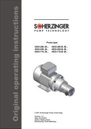
Original operating instructions<br />
Pump models<br />
<strong>3030</strong>-045-<strong>ZK</strong>... <strong>3030</strong>-045-B-<strong>ZK</strong>...<br />
<strong>3030</strong>-070-<strong>ZK</strong>... <strong>3030</strong>-070-B-<strong>ZK</strong>...<br />
<strong>3030</strong>-110-<strong>ZK</strong>... <strong>3030</strong>-110-B-<strong>ZK</strong>...<br />
© 2011 <strong>Scherzinger</strong> Pump Technology<br />
Version: 1.4<br />
Date: 22.10.2012<br />
Author: Markus Dold<br />
Checked: Erich Willimsky
Table of Contents<br />
0. Table of Contents<br />
0. Table of Contents ......................................................................................................................... 2<br />
1. General information ..................................................................................................................... 4<br />
1.1. Related documents ................................................................................................................ 4<br />
1.2. Intended use .......................................................................................................................... 4<br />
1.3. Product information ................................................................................................................ 4<br />
1.4. Pump dimensions .................................................................................................................. 5<br />
1.5. Nameplate description ........................................................................................................... 5<br />
1.6. Pump specifications ............................................................................................................... 6<br />
1.7. Noise Level ............................................................................................................................ 8<br />
1.8. Non-ionizing radiation ............................................................................................................ 8<br />
1.9. Foreign representatives ......................................................................................................... 8<br />
2. Safety ............................................................................................................................................ 9<br />
2.1. Labeling of notices in the operating instructions .................................................................... 9<br />
2.2. Protective clothing .................................................................................................................. 9<br />
2.3. Personnel qualification and training ..................................................................................... 10<br />
2.4. Dangers of failure to observe safety notices ........................................................................ 10<br />
2.5. Working in a safe manner .................................................................................................... 10<br />
2.6. Safety notices for the operator ............................................................................................. 10<br />
2.7. Safety notices for maintenance, inspection, and assembly tasks ....................................... 10<br />
2.8. Unauthorized conversion and production of spare parts ..................................................... 11<br />
2.9. Impermissible operating methods ........................................................................................ 11<br />
3. General danger points ............................................................................................................... 12<br />
3.1. Hazards presented by the pumped liquid ............................................................................ 12<br />
3.2. Danger of electrical energy .................................................................................................. 12<br />
3.3. Dangers of the magnetic coupling ....................................................................................... 12<br />
3.4. Danger of moving parts ........................................................................................................ 12<br />
3.5. Hazards caused by hot components ................................................................................... 12<br />
3.6. Hazards caused by dust ...................................................................................................... 12<br />
3.7. Hazards of special fields of operation .................................................................................. 13<br />
4. Description of the pump ............................................................................................................ 14<br />
4.1. How a gear pump works ...................................................................................................... 14<br />
4.2. Structural design of the pump head ..................................................................................... 14<br />
4.2.1. Basic design ................................................................................................................... 14<br />
4.2.2. Pressure relief valve, only on <strong>3030</strong>-045-B, <strong>3030</strong>-070-B, and <strong>3030</strong>-110-B .................... 14<br />
4.2.3. Magnetic coupling .......................................................................................................... 15<br />
5. Transport and storage ............................................................................................................... 16<br />
5.1. Shipping the pumps and protective measures ..................................................................... 16<br />
5.2. Transport .............................................................................................................................. 16<br />
5.3. Storage ................................................................................................................................. 16<br />
5.4. Preservation for storage after operation/flushing of the pump ............................................. 16<br />
5.5. Sending the pump back to the factory ................................................................................. 16<br />
6. Set-up/Installation ...................................................................................................................... 17<br />
6.1. Place of installation .............................................................................................................. 17<br />
6.2. Installation position .............................................................................................................. 17<br />
6.3. Installing the magnetic coupling ........................................................................................... 17<br />
6.4. Electric drive......................................................................................................................... 18<br />
6.5. Initial installation ................................................................................................................... 18<br />
6.6. Connection lines .................................................................................................................. 20<br />
7. Starting/stopping ....................................................................................................................... 22<br />
7.1. Preparing for operation ........................................................................................................ 22<br />
7.2. Startup .................................................................................................................................. 22<br />
7.3. Adjusting the pressure relief valve (<strong>3030</strong>-045-B, <strong>3030</strong>-070-B, and <strong>3030</strong>-110-B only) ........ 22<br />
7.4. Monitoring ............................................................................................................................ 23<br />
7.5. Taking the pump out of operation ........................................................................................ 25<br />
7.6. Removal from the system .................................................................................................... 25<br />
7.7. Disposing of the pump ......................................................................................................... 26<br />
8. Maintenance ............................................................................................................................... 27<br />
2 Operating instruction for: <strong>3030</strong>-045-<strong>ZK</strong>..., <strong>3030</strong>-070-<strong>ZK</strong>..., <strong>3030</strong>-110-<strong>ZK</strong>..., <strong>3030</strong>-045-B-<strong>ZK</strong>..., <strong>3030</strong>-070-B-<strong>ZK</strong>..., <strong>3030</strong>-110-B-<strong>ZK</strong>...
Table of Contents<br />
8.1. General notices .................................................................................................................... 27<br />
8.2. Maintenance cycle ............................................................................................................... 27<br />
8.3. Disassembly and reassembly .............................................................................................. 27<br />
8.3.1. Assembly tools ............................................................................................................... 27<br />
8.3.2. Pump body ..................................................................................................................... 27<br />
8.3.3. Pressure relief valve only on <strong>3030</strong>-045-B, <strong>3030</strong>-070-B, and <strong>3030</strong>-110-B ..................... 28<br />
9. Disturbances, causes, removal ................................................................................................ 30<br />
10. Spare parts ................................................................................................................................. 33<br />
10.1. List of spare parts .............................................................................................................. 33<br />
10.2. Exploded drawing .............................................................................................................. 34<br />
11. Safety Declaration ...................................................................................................................... 35<br />
12. Declaration of conformity according to directive 94/9/EC (ATEX95).................................... 36<br />
13. Declaration of conformity according to directive 2006/42/EC (machinery directive) ......... 37<br />
14. Table of Figures ......................................................................................................................... 38<br />
15. Directory of Tables .................................................................................................................... 38<br />
Version: 1.4 Date: 22.10.2012 3
General information<br />
1. General information<br />
These original operating instructions contain important notices that must be observed during setup,<br />
operation, and maintenance. For this reason, the installer and all technical personnel/operators<br />
must read these operating instructions before installation and operation; these instructions must<br />
remain with the machine at all times.<br />
In addition to the operating instructions for the pump, read the operating instructions for the drive<br />
and keep them readily accessible.<br />
Numbers placed within brackets “[ ]” after individual pump parts refer to item numbers in Section<br />
10.1 page 33.<br />
1.1. Related documents<br />
1.2. Intended use<br />
• Optional: Technical documentation for the temperature monitor (PT100).<br />
The pumps described in these operating instructions are designed to move liquids that are not<br />
corrosive or aggressive towards the utilized materials (Section 1.7, page 7). In the following text,<br />
suitable liquid is referred to simply as "liquid."<br />
If you require additional information not contained in these operating instructions, please contact<br />
Ernst <strong>Scherzinger</strong> GmbH & Co. KG, 78120 Furtwangen, Germany. If you require assistance,<br />
indicate the exact model and serial number of the pump. The pump type (Typ), year of manufacture<br />
(Bj.), and serial number (Nr.) are located on the pump’s nameplate (Section 5, page 5).<br />
1.3. Product information<br />
These operating instructions apply to pump types<br />
<strong>3030</strong>-045-<strong>ZK</strong>...<br />
<strong>3030</strong>-070-<strong>ZK</strong>...<br />
<strong>3030</strong>-110-<strong>ZK</strong>...<br />
<strong>3030</strong>-045-B-<strong>ZK</strong>...<br />
<strong>3030</strong>-070-B-<strong>ZK</strong>...<br />
<strong>3030</strong>-110-B-<strong>ZK</strong>...<br />
manufactured by Ernst <strong>Scherzinger</strong> GmbH & Co. KG, 78120 Furtwangen, Germany, beginning in<br />
January of 2010.<br />
The pumps are numbered consecutively. Serial numbers begin at zero each year.<br />
The date of release and version of the operating instructions can be seen on the title page and at<br />
the footer of these operating instructions.<br />
4 Operating instruction for: <strong>3030</strong>-045-<strong>ZK</strong>..., <strong>3030</strong>-070-<strong>ZK</strong>..., <strong>3030</strong>-110-<strong>ZK</strong>..., <strong>3030</strong>-045-B-<strong>ZK</strong>..., <strong>3030</strong>-070-B-<strong>ZK</strong>..., <strong>3030</strong>-110-B-<strong>ZK</strong>...
General information<br />
1.4. Pump dimensions<br />
Pump variations without motor:<br />
G1/4 both sides<br />
g set up correct<br />
by assembling<br />
feather key groove<br />
DIN6885 - 4x4x...<br />
sense of<br />
rotation<br />
inlet<br />
outlet<br />
O 70<br />
O 50<br />
2,8<br />
O h<br />
O i<br />
O k<br />
90° (4x)<br />
45°<br />
O l<br />
f<br />
e<br />
d<br />
c<br />
b<br />
a 0<br />
O m<br />
Pump models<br />
Dimensions (mm)<br />
a b c d e f g h i k l m<br />
<strong>3030</strong>-045-<strong>ZK</strong>63-120 3,5 8,0 23,5 57,5 71,5 108,0 45,5 11G7 80H7 120,0 6,3 100,0<br />
<strong>3030</strong>-070-<strong>ZK</strong>63-120 3,5 8,0 23,5 57,5 71,5 112,0 45,5 11G7 80H7 120,0 6,3 100,0<br />
<strong>3030</strong>-110-<strong>ZK</strong>63-120 3,5 8,0 23,5 57,5 71,5 118,0 45,5 11G7 80H7 120,0 6,3 100,0<br />
<strong>3030</strong>-045-B-<strong>ZK</strong>63-120 3,5 8,0 23,5 57,5 71,5 114,0 45,5 11G7 80H7 120,0 6,3 100,0<br />
<strong>3030</strong>-070-B-<strong>ZK</strong>63-120 3,5 8,0 23,5 57,5 71,5 118,0 45,5 11G7 80H7 120,0 6,3 100,0<br />
<strong>3030</strong>-110-B-<strong>ZK</strong>63-120 3,5 8,0 23,5 57,5 71,5 124,0 45,5 11G7 80H7 120,0 6,3 100,0<br />
<strong>3030</strong>-045-<strong>ZK</strong>71-140 3,5 15,0 31,0 65,0 79,0 115,5 53,0 14G7 95H7 140,0 8,4 115,0<br />
<strong>3030</strong>-070-<strong>ZK</strong>71-140 3,5 15,0 31,0 65,0 79,0 119,5 53,0 14G7 95H7 140,0 8,4 115,0<br />
<strong>3030</strong>-110-<strong>ZK</strong>71-140 3,5 15,0 31,0 65,0 79,0 125,5 53,0 14G7 95H7 140,0 8,4 115,0<br />
<strong>3030</strong>-045-B-<strong>ZK</strong>71-140 3,5 15,0 31,0 65,0 79,0 121,5 53,0 14G7 95H7 140,0 8,4 115,0<br />
<strong>3030</strong>-070-B-<strong>ZK</strong>71-140 3,5 15,0 31,0 65,0 79,0 125,5 53,0 14G7 95H7 140,0 8,4 115,0<br />
<strong>3030</strong>-110-B-<strong>ZK</strong>71-140 3,5 15,0 31,0 65,0 79,0 131,5 53,0 14G7 95H7 140,0 8,4 115,0<br />
Figure 1 Dimensions without motor<br />
1.5. Nameplate description<br />
Nameplate without motor:<br />
Flange diameter<br />
Mounting flange<br />
Basic variation<br />
Rating<br />
Basic type<br />
Month<br />
Year<br />
Serial number<br />
Figure 2 Nameplate without motor<br />
Version: 1.4 Date: 22.10.2012 5
General information<br />
1.6. Pump specifications<br />
Max. differential pressure<br />
12 bar<br />
Max. system pressure (pressure side) 100 bar<br />
Max. suction negative pressure<br />
0.9 bar (filled with liquid)<br />
Operating temperature<br />
-20 to 130 °C with PEEK gears /bearing<br />
-20 to 70 °C with PTFE gears/bearing<br />
Viscosity range 0.5 to 10.000 mm 2 /s<br />
Speed range<br />
0 to 4000 1/min<br />
Noise level<br />
< 50 dB(A) measured at 2500 1/min,<br />
Speed 2500 1/min,<br />
Operating pressure 2 bar<br />
Operating temperature 20 °C<br />
Liquid 1 mm²/s,<br />
Non-lubricating<br />
Storage temperature 5°C to 50°C<br />
Dimensions<br />
Refer to data sheets<br />
<strong>3030</strong>-045-<strong>ZK</strong>... <strong>3030</strong>-045-B-<strong>ZK</strong>...<br />
<strong>3030</strong>-070-<strong>ZK</strong>... <strong>3030</strong>-070-B-<strong>ZK</strong>...<br />
<strong>3030</strong>-110-<strong>ZK</strong>... <strong>3030</strong>-110-B-<strong>ZK</strong>...<br />
in Section 1.4, page 5<br />
Max. possible speed in terms of liquid viscosity<br />
4500<br />
max. Pump speed (1/min)<br />
4000<br />
3500<br />
3000<br />
2500<br />
2000<br />
1500<br />
1000<br />
500<br />
0<br />
1 10 100 1000 10000<br />
Liquid viscosity (mm²/s)<br />
Figure 3 Viscosity range<br />
Capacity in terms of differential pressure for pumps <strong>3030</strong>-045 and <strong>3030</strong>-045-B<br />
Viscosity 1mm²/s:<br />
output volume (l/min)<br />
1,4<br />
1,2<br />
1<br />
0,8<br />
0,6<br />
0,4<br />
0,2<br />
Q @ 2900 1/min<br />
Q @ 1450 1/min<br />
Q @ 720 1/min<br />
0<br />
0 1 2 3 4 5 6 7 8 9 10<br />
differential pressure (bar)<br />
Figure 4 Differential pressure range for pumps <strong>3030</strong>-045 and <strong>3030</strong>-045-B<br />
6 Operating instruction for: <strong>3030</strong>-045-<strong>ZK</strong>..., <strong>3030</strong>-070-<strong>ZK</strong>..., <strong>3030</strong>-110-<strong>ZK</strong>..., <strong>3030</strong>-045-B-<strong>ZK</strong>..., <strong>3030</strong>-070-B-<strong>ZK</strong>..., <strong>3030</strong>-110-B-<strong>ZK</strong>...
General information<br />
Capacity in terms of differential pressure for pumps <strong>3030</strong>-070 and <strong>3030</strong>-070-B<br />
Viscosity 1mm²/s:<br />
output volume (l/min)<br />
2,5<br />
2<br />
1,5<br />
1<br />
0,5<br />
Q @ 2900 1/min<br />
Q @ 1450 1/min<br />
Q @ 720 1/min<br />
0<br />
0 1 2 3 4 5 6 7 8 9 10<br />
differential pressure (bar)<br />
Figure 5 Differential pressure range for pumps <strong>3030</strong>-070 and <strong>3030</strong>-070-B<br />
Capacity in terms of differential pressure for pumps <strong>3030</strong>-110 and <strong>3030</strong>-110-B<br />
Viscosity 1mm²/s:<br />
output volume (l/min)<br />
3,5<br />
Q @ 2900 RPM<br />
3<br />
Q @ 1450 RPM<br />
2,5<br />
Q @ 720 RPM<br />
2<br />
1,5<br />
1<br />
0,5<br />
0<br />
0 1 2 3 4 5 6 7 8 9 10<br />
differential pressure (bar)<br />
Figure 6 Differential pressure for pumps <strong>3030</strong>-110 and <strong>3030</strong>-110-B<br />
Parts contacting liquid:<br />
Casing [1], [2], [16]: 1.4404<br />
Shafts [3], [4] 1.4404<br />
Gears [5], bearing [6]<br />
PEEK mod,<br />
PTFE 25 % carbon in type /TE<br />
Magnetic coupling hub [14] 1.4404<br />
Locking screw [25]<br />
A4<br />
Valve plate [30]<br />
PTFE<br />
Adjustment screw [31] 1.4404<br />
Seals [28], [33]<br />
PTFE<br />
Pressure spring [34] 1.4568<br />
Pumped liquid<br />
Observe the resistance of the materials listed<br />
above.<br />
If one or more of the limit values described in this section are exceeded, contact the factory to<br />
request manufacturer approval for these operating conditions. If approval is not possible, the pump<br />
will require modification for use with your application. Failure to do this may damage or destroy the<br />
pump or the system in which the pump is integrated, and may represent a risk of personal injury.<br />
Version: 1.4 Date: 22.10.2012 7
General information<br />
1.7. Noise Level<br />
Noise level was measured under the following conditions:<br />
Sensor distance from pump: 1 m<br />
The pump's noise level is below 70 dB(A) at all operating points.<br />
1.8. Non-ionizing radiation<br />
A pump with a magnetic coupling emits non-ionizing radiation in the form of a magnetic field. This<br />
radiation may destroy magnetically sensitive products. Examples of such products include:<br />
• implanted medical devices such as pacemakers<br />
• credit cards<br />
• electric, electronic, and finely-engineered mechanical devices such as hard drives.<br />
Refer to Section 3.3 page 12 for essential special safety notices.<br />
1.9. Foreign representatives<br />
A list of our global representatives, including addresses, can be requested from the factory or<br />
downloaded at www.scherzinger.de.<br />
Most representatives are sales subsidiaries; some perform repairs and maintenance. However,<br />
most repairs and maintenance are performed at our main factory in Furtwangen, Germany.<br />
.<br />
8 Operating instruction for: <strong>3030</strong>-045-<strong>ZK</strong>..., <strong>3030</strong>-070-<strong>ZK</strong>..., <strong>3030</strong>-110-<strong>ZK</strong>..., <strong>3030</strong>-045-B-<strong>ZK</strong>..., <strong>3030</strong>-070-B-<strong>ZK</strong>..., <strong>3030</strong>-110-B-<strong>ZK</strong>...
Safety<br />
2. Safety<br />
Observe not only the general safety notices under this section "Safety," but also the special safety<br />
notices described under the other main points.<br />
2.1. Labeling of notices in the operating instructions<br />
Failure to observe the safety notices contained in these operating instructions can lead to<br />
hazardous situations. These notices are labeled as follows:<br />
Failure to observe will result in personal hazards.<br />
Failure to observe will result in the hazard of electrical voltage.<br />
These notices regarding explosion protection must be observed at all times. Failure<br />
to observe these notices will result in a risk of explosion and personal injury.<br />
WARNING<br />
Failure to observe these notices may damage or destroy the machine.<br />
Observe the nameplate attached to the pump and keep it completely readable at all times.<br />
2.2. Protective clothing<br />
Safety glasses<br />
Wear safety glasses when working with the machine to protect against<br />
spraying liquids or flying parts.<br />
Protective gloves<br />
Wear protective gloves at all times when working with the machine.<br />
Protective shoes<br />
Wear sturdy, insulated safety shoes with steel tips for protection from<br />
falling parts.<br />
Ear protection<br />
To avoid hearing damage, always wear ear protection when working<br />
within the machine's/system's noise range.<br />
Protective clothing<br />
Always wear clothing that will provide suitable protection from the liquid<br />
being pumped.<br />
Version: 1.4 Date: 22.10.2012 9
Safety<br />
2.3. Personnel qualification and training<br />
Personnel who perform assembly, operation, and maintenance tasks must be properly qualified.<br />
The operator is responsible for clearly defining areas of responsibility, monitoring personnel, and<br />
ensuring that all regulations are followed. If the personnel lack the required knowledge, they must<br />
be provided with training and instruction. The operator must also ensure that the personnel fully<br />
understand the operating instructions and can view the operating instructions at any time.<br />
People who have active or inactive implanted medical devices such as heart pacemakers must not<br />
work on magnetic parts and must stay away from pumps with magnetic couplings. It is the<br />
operator’s responsibility to see that all employees who have contact with the machine are informed<br />
of the possible dangers.<br />
2.4. Dangers of failure to observe safety notices<br />
Failure to observe the safety notices can result in dangers to people and the environment, as well<br />
damage to the pump. Failure to observe safety notices may lead to loss of any damage<br />
compensation claims. Specifically, failure to observe safety notices may result in the following<br />
dangers:<br />
• Failure of important pump functions.<br />
• Failure of required methods for maintenance and repair.<br />
• Electrical, mechanical, and chemical hazards.<br />
• Environmental damages caused by escape of hazardous materials.<br />
• Thermal non-ionizing radiation in the form of a magnetic field.<br />
2.5. Working in a safe manner<br />
The safety notices contained in these operating instructions, current national regulations for<br />
accident prevention, and any internal working, operating, and safety regulations specified by the<br />
operator must be observed at all times.<br />
2.6. Safety notices for the operator<br />
Operate the pump only in a technically flawless condition in compliance with regulations and the<br />
operating instructions.<br />
As operator, you are required to provide personal protective equipment.<br />
If hot or cold parts create a hazard, as operator you must secure these parts against contact at the<br />
site of installation.<br />
Leaks of hazardous (explosive, toxic, or hot) liquids must be diverted in such a way that they will<br />
not represent a hazard for people or the environment. Always obey all legally defined directives.<br />
Regularly remove dust deposits if they lead to dangers when operating the pump in a potentially<br />
explosive atmosphere.<br />
Eliminate any hazards associated with electrical energy (refer to regulations of the Association for<br />
Electrical, Electronic & Information Technologies (VDE) and local power companies).<br />
2.7. Safety notices for maintenance, inspection, and assembly tasks<br />
The operator must ensure that all maintenance and assembly tasks are performed by authorized<br />
and qualified personnel who have obtained adequate information through careful reading of the<br />
operating instructions.<br />
• Work on the pump may be performed only when the pump is shut off.<br />
• Shut off the motor's power supply and lock it in the off position before all assembly and<br />
maintenance tasks.<br />
• Pumps or systems that move hazardous liquids must be decontaminated.<br />
• Ensure that the pump is not located within a potentially explosive atmosphere. Ventilate,<br />
inert, or move the pump to an area that is not potentially explosive.<br />
• Always wear personal protective equipment (see Section 2.2, page 9).<br />
• Immediately after concluding work, replace all safety and protection devices and ensure<br />
that they are operational.<br />
• The points listed under Section 0, "Initial startup” (page 21), must be observed before<br />
bringing the machine into operation.<br />
•<br />
10 Operating instruction for: <strong>3030</strong>-045-<strong>ZK</strong>..., <strong>3030</strong>-070-<strong>ZK</strong>..., <strong>3030</strong>-110-<strong>ZK</strong>..., <strong>3030</strong>-045-B-<strong>ZK</strong>..., <strong>3030</strong>-070-B-<strong>ZK</strong>..., <strong>3030</strong>-110-B-<strong>ZK</strong>...
Safety<br />
2.8. Unauthorized conversion and production of spare parts<br />
Changes to or conversion of the pump is permissible only with the approval of the manufacturer.<br />
Unauthorized interventions may damage the pump and the attached system and/or cause injury.<br />
Original spare parts and manufacturer-approved accessories promote safety. Use of other parts<br />
may nullify liability for any resulting consequences.<br />
2.9. Impermissible operating methods<br />
Operational safety of the delivered machine is ensured only through proper use as described in<br />
Section 1, “General information” (page 4), of the operating instructions. The values specified in the<br />
data sheet and in Section1.6, page 6 may not be exceeded under any circumstances. Operating<br />
the machine outside of these specifications may damage the machine and result in injury. The<br />
manufacturer is not liable for damages caused by operating the machine beyond its limitations.<br />
Version: 1.4 Date: 22.10.2012 11
General danger points<br />
3. General danger points<br />
In spite of all safety measures, danger to life and limb of the user or third parties may arise during<br />
use of the pump, or damage may occur to the system or other property.<br />
3.1. Hazards presented by the pumped liquid<br />
Escaping or squirting liquid represents a danger of injury or poisoning. Always wear appropriate<br />
protective clothing (see Section 2.2, page 9) when working with the pump.<br />
Examples of hazardous liquid include:<br />
• Potentially explosive liquids<br />
• Flammable liquids<br />
• Corrosive liquids<br />
• Toxic liquids<br />
• Radioactive liquids<br />
• Irritating liquids<br />
• Liquids that are hazardous to health<br />
• Carcinogenic liquids<br />
• Hot liquids<br />
• Cold liquids<br />
3.2. Danger of electrical energy<br />
All work on the electrical supply must be performed by trained electricians.<br />
Direct or indirect contact with voltage-carrying parts, high voltage, electromagnetic and magnetic<br />
fields, and short circuits represents electrical hazards for anyone working on the pump/system. To<br />
minimize these hazards, observe the relevant safety notices and take safety precautions (see<br />
Section 2, page 8).<br />
3.3. Dangers of the magnetic coupling<br />
The magnetic coupling’s magnetic field represents a danger to life and property.<br />
Please observe the following points:<br />
• People with heart pacemakers may not perform any work on the pump.<br />
• Make sure that people with heart pacemakers maintain a distance of at least 1 m.<br />
• Make sure that no magnetizable metal parts can be attracted to the magnetic coupling.<br />
• Make sure that objects sensitive to magnetization maintain a distance of at least 150 mm.<br />
3.4. Danger of moving parts<br />
Safety components attached to the pump that are designed to provide protection from moving parts<br />
may not be removed while the pump/system is in operation.<br />
3.5. Hazards caused by hot components<br />
If hot components present a danger, install protective devices to prevent contact with the hot<br />
components.<br />
3.6. Hazards caused by dust<br />
When operating the pump in a dusty environment, regularly remove dust that collects on the<br />
surface of the pump and motor. Increase the frequency of dust removal based on the amount of<br />
dust. If a large amount of dust collects on the pump or motor, excessive heat may build up and<br />
spontaneous combustion may occur.<br />
12 Operating instruction for: <strong>3030</strong>-045-<strong>ZK</strong>..., <strong>3030</strong>-070-<strong>ZK</strong>..., <strong>3030</strong>-110-<strong>ZK</strong>..., <strong>3030</strong>-045-B-<strong>ZK</strong>..., <strong>3030</strong>-070-B-<strong>ZK</strong>..., <strong>3030</strong>-110-B-<strong>ZK</strong>...
General danger points<br />
3.7. Hazards of special fields of operation<br />
if using the pump to transport food or for applications related to cosmetics or pharmaceuticals,<br />
exercise special care when using cleaning, disinfecting, or flushing agents.<br />
Make sure that the pumped liquids do not become contaminated with residual cleaning and/or<br />
flushing/disinfecting agents. It is advisable to use only liquids that, in the event of contamination to<br />
the pumped liquid, will not have harmful effects.<br />
Take precautions to ensure complete removal of residuals before resuming operation.<br />
Refer to Section 5.4, page 16 for instructions on proper flushing of the pump.<br />
Version: 1.4 Date: 22.10.2012 13
Description of the pump<br />
4. Description of the pump<br />
4.1. How a gear pump works<br />
In a gear pump, two counter-rotating gears within a pump casing generate the pumping action. The<br />
gears are attached to two shafts whose bearings are located in the pump casing and pump cover.<br />
One of the two gears is driven by a shaft; the second gear is driven by meshing with the first gear.<br />
As gaps open between the teeth of the gears, negative pressure is generated that sucks the liquid<br />
into the pump and transports it between the tooth gaps and the wall of the casing. When the liquid<br />
reaches the other side of the gears (where they again mesh with each other), it is pushed out of the<br />
gaps between the teeth and into the discharge section of the pump. As a result, liquid can also be<br />
pumped against positive pressure.<br />
Figure 7 How a gear pump works<br />
4.2. Structural design of the pump head<br />
4.2.1. Basic design<br />
The pump head consists of two parts, the casing [1] and the cover [2]. This design permits simple,<br />
rapid, and economical maintenance and repair. The casing [1] and the cover [2] are screwed<br />
together with two screws [21]. Two centering bushes [7] determine the exact positions of these<br />
parts relative to each other. A seal [28] is installed between the casing and the cover. The gears [5]<br />
pressed onto the shafts [3], [4] are mounted axially in the casing and the cover. The shaft bearing<br />
in the casing and cover is provided by plain bearings [6]. The rotational motion is transferred from<br />
the drive unit to the pump via a magnetic coupling [14], a drive shaft [3], and a drive gear [5].<br />
<strong>Scherzinger</strong> laboratory pump heads of the <strong>3030</strong> series are available in three different sizes (size –<br />
045 to size –110). Theoretical pump capacities are as follows:<br />
Pump head Vg th Displacement Q th at 1400 1/min Q th at 2800 1/min<br />
-045 and -045-B 0.45 cm³/U 0.63 l/min 1.26 l/min<br />
-070 and -070-B 0.70 cm³/U 0.98 l/min 1.96 l/min<br />
-110 and -110-B 1.10 cm³/U 1.54 l/min 3.08 l/min<br />
Table 1 Pump data<br />
4.2.2. Pressure relief valve, only on <strong>3030</strong>-045-B, <strong>3030</strong>-070-B, and <strong>3030</strong>-110-B<br />
The pressure relief valve (bypass valve) provides pressure relief. Its adjustment range is from 0,5<br />
to 15,0 bar.<br />
When the valve is triggered, the liquid is directed back internally from the pressure side to the<br />
suction side, thereby avoiding any damage to the system or pump head.<br />
Refer to Section 7.3, page 22 for instructions on proper valve adjustment.<br />
14 Operating instruction for: <strong>3030</strong>-045-<strong>ZK</strong>..., <strong>3030</strong>-070-<strong>ZK</strong>..., <strong>3030</strong>-110-<strong>ZK</strong>..., <strong>3030</strong>-045-B-<strong>ZK</strong>..., <strong>3030</strong>-070-B-<strong>ZK</strong>..., <strong>3030</strong>-110-B-<strong>ZK</strong>...
Description of the pump<br />
4.2.3. Magnetic coupling<br />
WARNING<br />
The magnetic coupling hermetically seals the pump head. In other words, it is not necessary for a<br />
rotating shaft end to protrude outward. As a result, wear-induced leaks are not possible because O-<br />
rings [28] are used only for static seals.<br />
Six alternately-magnetized magnets on the inner circumference of the magnetic coupling bell [15]<br />
transfer torque through a non-magnetizable separating wall (containment can [16]) to the magnetic<br />
coupling hub [14]. Another six magnets with alternating polarity are arranged on the outer<br />
circumference of the coupling hub.<br />
On <strong>3030</strong>-045-B, <strong>3030</strong>-070-B, and <strong>3030</strong>-110-B only, the magnetic coupling (in addition to the<br />
pressure relief valve) acts as an overload protector which prevents damage to the pump head at<br />
higher pressures. As soon as the maximum amount of transferable torque is exceeded, the<br />
magnetic field disconnects and the drive continues to run with almost no resistance. The system<br />
starts to rattle uniformly and the pump head comes to a standstill. Pumping ceases.<br />
Operating times of more than two minutes in the decoupled condition will cause the magnets to<br />
heat up, and the magnets may become demagnetized. If this happens, the amount of transferred<br />
torque (and thereby the level of pressure that can be achieved) will decrease. Avoid operating the<br />
pump in this condition.<br />
[15]<br />
[16]<br />
[14]<br />
Figure 8 Magnetic coupling<br />
rotating<br />
magnetic<br />
force<br />
Version: 1.4 Date: 22.10.2012 15
Transport and storage<br />
5. Transport and storage<br />
5.1. Shipping the pumps and protective measures<br />
The pumps are sent from the factory in a way that protects them against impacts and blows. Inlets<br />
and outlets are also sealed with protective plugs. These measures are required in order to prevent<br />
the escape of any liquid that remains in the pump head after a test run. Connection threads are<br />
also protected in this way. This reliably prevents penetration of foreign objects into the pump.<br />
5.2. Transport<br />
5.3. Storage<br />
Pumps that leave our factory are in a flawless condition and are sent in appropriate packaging<br />
materials. Immediately after receiving your pumps, inspect them for damage incurred during<br />
transport. If damage is discovered, immediately report this to the freight forwarding company and<br />
<strong>Scherzinger</strong> Pump Technology.<br />
If placing the pump into storage, observe the following points:<br />
• Do not store the pump in wet or moist areas.<br />
• Insert the protective plugs or leave them in place.<br />
• If placing the pump into storage for more than six months, apply corrosion protection to<br />
uncoated metal parts.<br />
• Ensure that storage areas do not contain ozone-generating equipment such as<br />
fluorescent light sources, mercury vapor lamps, or electric high-voltage devices.<br />
• Prevent the formation of condensation. Ideally, relative air humidity should be below<br />
65%. Avoid higher air humidity.<br />
5.4. Preservation for storage after operation/flushing of the pump<br />
WARNING<br />
The pump must be prepared for storage in different ways depending on the liquid pumped. If no<br />
toxic or aggressive liquids were pumped, flush the pump briefly with water at low speed without<br />
increasing differential pressure.<br />
If toxic or aggressive liquids were pumped, clean the pump in a way that any subsequent<br />
maintenance tasks can be performed without endangering the health of personnel. Flush the pump<br />
at medium speed with a neutralizing liquid. Disassemble and manually clean the parts that were<br />
not completely cleaned during the flushing process. Pay special attention to the magnetic coupling<br />
and the pressure relief valve (if present).<br />
If solidifying liquids (such as coatings) were pumped, the pump must be completely disassembled<br />
and each individual part of the pump must be cleaned in order to ensure flawless functionality when<br />
the pump is restarted. Use conventional cleaning agents or solvents (refer to Section 1.7, page 7<br />
for information about resistance). After reassembling the pump, flush it once more with water at<br />
medium speed.<br />
Observe all regulations on handling hazardous materials!<br />
5.5. Sending the pump back to the factory<br />
If sending the pump back to the factory for repair or maintenance, you must completely fill out the<br />
Safety Declaration in Section 11 on page 34 and include it with the shipment. Failure to do this will<br />
prevent us from handling your repair!<br />
There is a danger of chemical burns or explosion when certain pumped liquids react with the<br />
flushing/cleaning agent.<br />
To eliminate the possibility of a dangerous chemical reaction between the pumped liquid and the<br />
flushing/cleaning agent, use a flushing/cleaning agent that is compatible with the most recently<br />
pumped liquid.<br />
16 Operating instruction for: <strong>3030</strong>-045-<strong>ZK</strong>..., <strong>3030</strong>-070-<strong>ZK</strong>..., <strong>3030</strong>-110-<strong>ZK</strong>..., <strong>3030</strong>-045-B-<strong>ZK</strong>..., <strong>3030</strong>-070-B-<strong>ZK</strong>..., <strong>3030</strong>-110-B-<strong>ZK</strong>...
Set-up/Installation<br />
6. Set-up/Installation<br />
6.1. Place of installation<br />
WARNING<br />
When selecting the place of installation, make sure that it has adequate space for maintenance and<br />
repair tasks. Make sure that you can easily remove and reinstall the pump.<br />
Do not install the pump in an aggressive atmosphere.<br />
6.2. Installation position<br />
WARNING<br />
Please observe that the pump unit is designed for horizontal installation. In exceptional cases, the<br />
pump unit can be installed vertically, however please observe that the drive unit is positioned<br />
above the pump. In this case increased noise emission can be expected.<br />
6.3. Installing the magnetic coupling<br />
Slide the magnetic coupling bell [15] loosely onto the motor shaft. Make sure that the threaded pin<br />
[24] is pointing down. Screw the motor onto the motor flange. The magnetic coupling bell will<br />
independently align in the axial direction in response to the magnetic force.<br />
Remove the screw plug [19] and seal ring [26], and tighten the threaded pin [24] with a 3mm<br />
hexagonal screwdriver. Then reassemble the seal ring and screw plug.<br />
Figure 9 Assembling the magnetic coupling<br />
Version: 1.4 Date: 22.10.2012 17
Set-up/Installation<br />
6.4. Electric drive<br />
WARNING<br />
The pump described in these operating instructions is delivered without an electric drive (-<strong>ZK</strong>…).<br />
The drive used with the pump can/must comply with IEC type IMB34, size 63, with a shaft<br />
geometry of 11 dia. x 23 mm, and a flange outer diameter of 120 mm, or type IMB34, size 71, with<br />
a shaft geometry of 14 dia. x 30 mm, and flange outer diameter of 140 mm, according to IEC.<br />
When selecting the motor, observe the pump dimensions specified in Section 1.4.<br />
Did not exceed the maximum permissible ceiling speed or the maximum permissible speed as<br />
appropriate for the liquid viscosity (Section 1.6, page 6).<br />
When assembling the unit, pay special attention to the position of the screw plug [19]. When<br />
installation is complete, the screw plug must point down!<br />
Also note the explosion protection class of the pump and the other components. This information is<br />
provided on the nameplates of each component. When operating in potentially explosive areas, the<br />
lowest ignition protection class of all of the components is applicable.<br />
Ground the motor/pump-unit to the drive's connection terminal provided for this purpose. When<br />
installing the motor, do not place any insulating elements between the pump bracket and the motor.<br />
The connecting bolts between the pump/motor and base plate must be made from electricallyconductive<br />
material, such as steel.<br />
Perform installation work only while the drive unit is shut off.<br />
WARNING<br />
Never install motor-driven pumps in tight quarters without adequate ventilation, as the motor will<br />
not cool properly and may overheat.<br />
The motor's electrical connection must be established in accordance with VDE directives and any<br />
directives established by the local power supply company. Also observe the operating instructions<br />
for the selected motor.<br />
Because a variety of motors are available, this document does not provide great detail about the<br />
drive. Always comply with the motor manufacturer's documentation.<br />
6.5. Initial installation<br />
WARNING<br />
Observe the ignition protection class of not only the pump, but of all installed components. The<br />
nameplates of each component provide the necessary information. When operating in potentially<br />
explosive areas, the lowest ignition protection class of all of the components is applicable.<br />
First, perform a visual inspection to discover any damage to the pump that may have been caused<br />
during transportation (see Section 5, page 15).<br />
Then check the following items to make sure you have the correct pump type:<br />
• Corrosion behavior of liquid<br />
• Liquid viscosity<br />
• The liquid that will be pumped<br />
• Pump capacity (flow rate)<br />
• Model and version<br />
• Direction of rotation or position of the suction/discharge sides<br />
• Temperature range<br />
If you discover any differences between the pump required for your system and the pump we have<br />
delivered, please contact us immediately. Do not bring the pump into operation without contacting<br />
us first.<br />
Screw the pumps/pump units only to the foot provided for this purpose. Make sure that the place of<br />
installation is level. Use suitable spacers to correct any unevenness near the connection points so<br />
the pump/pump unit is even across these four points. If strong vibrations occur during operation of<br />
the pump, follow the points provided in the Troubleshooting Table (Section 9, page 30).<br />
It is important that the drive turns the pump in the proper direction so that the pumping direction is<br />
correct. Reversing the direction of rotation will also reverse the flow direction. Pumps <strong>3030</strong>-045,<br />
<strong>3030</strong>-070, and <strong>3030</strong>-110 are capable of turning in either direction, so, in most cases, reversing the<br />
direction will not damage the pump. For pumps <strong>3030</strong>-045-B, <strong>3030</strong>-070-B, and <strong>3030</strong>-110-B, the<br />
instructed direction of rotation must be observed to avoid disabling the safety relief valve.<br />
18 Operating instruction for: <strong>3030</strong>-045-<strong>ZK</strong>..., <strong>3030</strong>-070-<strong>ZK</strong>..., <strong>3030</strong>-110-<strong>ZK</strong>..., <strong>3030</strong>-045-B-<strong>ZK</strong>..., <strong>3030</strong>-070-B-<strong>ZK</strong>..., <strong>3030</strong>-110-B-<strong>ZK</strong>...
Set-up/Installation<br />
Operating in the incorrect direction may cause significant damage to the system and present a<br />
danger for operating personnel.<br />
A fall test according to DIN <strong>EN</strong> 13 463-1, Section 13, page 37 has not been performed. Protect the<br />
pump as well as possible from shaking and impacts. Shaking or impacts may influence<br />
functionality, but not explosion protection.<br />
Version: 1.4 Date: 22.10.2012 19
Set-up/Installation<br />
6.6. Connection lines<br />
WARNING<br />
Before installing the suction and discharge lines, make sure that the piping's connection flanges<br />
match the flanges on the pump.<br />
No force or torque may be exerted on the pump through the connection lines. If the connection<br />
lines exert any force or torque on the pump, support the connection lines close to where they<br />
connect with the pump. Also make sure that no forces caused by heat expansion act on the pump.<br />
Use connection lines of adequate dimensions. Do not connect any lines whose nominal width is<br />
smaller than the nominal width of the pump connections. On the suction side of the pump, we<br />
recommend using connection lines that are one size larger than the pump's suction connection.<br />
The following table provides guidelines for the maximum flow speed in the lines:<br />
up to 200 mPas up to 600 mPas up to 2000 mPas<br />
Suction line 1.5 m/s 0.5 m/s 0.2 m/s<br />
Pressure line 3.0 m/s 1.0 m/s 0.5 m/s<br />
Table 2 Recommended flow speeds<br />
WARNING<br />
WARNING<br />
To avoid penetration of foreign objects that could lead to damage to the pump, install a suction filter<br />
with filter fineness of at least 50 µm. Choose a suction filter of an adequate size, so that its internal<br />
resistance will not negatively affect the pump's suction capabilities.<br />
Where bends in the lines are necessary, use the largest possible radius. Avoid sharp pipe elbows<br />
wherever possible.<br />
Install the suction line so it inclines upward towards the pump. If lines must be installed sloping<br />
upward and downward, provide ventilation at the highest positions.<br />
After installing the pipelines, make sure that they are free of deposits, chips, or other contaminants<br />
that could damage the pump when it starts.<br />
Ensure that all lines, valves, and screw fittings are perfectly sealed; improper sealing can result in<br />
gas entering through the suction side, and the pump will no longer generate suction. Liquid may<br />
also flow out on the pressure side.<br />
If the suction head reaches 3 m, we recommend installing a foot valve into the suction line. When<br />
the pump is shut off, this valve will prevent liquid from flowing back through the pump, or the<br />
suction line from emptying.<br />
In this situation, make sure that the pressure at the inlet is the same as the pressure at the<br />
discharge when the pump is stopped. When doing this, observe the maximum system pressures<br />
(see Section 1.6, page 6).<br />
Recommended installation in potentially explosive areas:<br />
just by:<br />
<strong>3030</strong>-045-B<br />
<strong>3030</strong>-070-B<br />
<strong>3030</strong>-110-B<br />
check<br />
valvel<br />
in out<br />
pump<br />
rising<br />
pipe<br />
filter<br />
temperature<br />
gauge<br />
Figure 10 Piping installation<br />
20 Operating instruction for: <strong>3030</strong>-045-<strong>ZK</strong>..., <strong>3030</strong>-070-<strong>ZK</strong>..., <strong>3030</strong>-110-<strong>ZK</strong>..., <strong>3030</strong>-045-B-<strong>ZK</strong>..., <strong>3030</strong>-070-B-<strong>ZK</strong>..., <strong>3030</strong>-110-B-<strong>ZK</strong>...
Set-up/Installation<br />
Noise-insulating elements, such as flexible hose connections, may be necessary on the piping.<br />
If you are not using the pump in a potentially explosive area, it may be useful to install stop valves<br />
immediately before and after the pump. Then, if the pump must be removed, it will not be<br />
necessary to empty the piping system.<br />
Version: 1.4 Date: 22.10.2012 21
Starting/stopping<br />
7. Starting/stopping<br />
7.1. Preparing for operation<br />
After installation is complete, inspect the pump and peripheral equipment once again using the<br />
following checklist:<br />
• Can you manually turn the pump (at the motor fan, for example)?<br />
• Have you properly connected the suction and pressure sides?<br />
• Does the drive's direction of rotation match the pump's direction of rotation?<br />
• Are the gate valves, butterfly valves, and other valves in the system in the proper<br />
positions?<br />
• Has the piping system been checked for leaks?<br />
• If a previously undiscovered or unanticipated malfunction occurs during initial startup,<br />
can the pump be stopped immediately (emergency stop)?<br />
• Is there an adequate quantity of the proper pumped liquid in the reserve container?<br />
• If the temperature difference between the pump and the pumped liquid is greater than<br />
50 °C, adjust the temperature of the pump before st arting.<br />
Perform assembly work only while the drive unit is shut off.<br />
7.2. Startup<br />
• If necessary, disinfect the pump head and piping system.<br />
• In order to avoid contaminating the pumped liquid, we recommend flushing for at least<br />
five minutes with the liquid that will be pumped, at an appropriate speed, to remove all<br />
residual quantities of any test liquid from the pump head.<br />
• Adjust the pressure relief valve according to Section 7.3 on page 22.<br />
• Do not allow the pump head to run dry for more than 30 seconds; longer dry-running<br />
times may destroy the pump.<br />
Make sure that the pumped liquid's ignition temperature is at least 50°K above the maximum<br />
permissible surface temperature of the pump.<br />
7.3. Adjusting the pressure relief valve (<strong>3030</strong>-045-B, <strong>3030</strong>-070-B, and <strong>3030</strong>-110-B only)<br />
The pressure relief valve is a safety valve for protecting the pump and the system. If you require<br />
precise pressure adjustment, you will need a more exact external pressure adjustment valve. Using<br />
the safety valve as a pressure relief valve can cause the discharge pressure to fluctuate.<br />
The integrated pressure relief valve allows you to set the relative pressure increase to a desired<br />
target value.<br />
The pressure relief valves are checked at the factory for proper functionality during the pump test<br />
run. The valve’s pressure is set at the factory only when specifically requested.<br />
Adjust the pressure relief valve while the pump is running. Measure the pressure increase on the<br />
pressure side of the pipework. Ensure that the proper conditions (operating conditions that will be<br />
encountered later) are present during adjustment.<br />
• Pumped liquid<br />
• Temperature<br />
• System pressure<br />
• Speed<br />
22 Operating instruction for: <strong>3030</strong>-045-<strong>ZK</strong>..., <strong>3030</strong>-070-<strong>ZK</strong>..., <strong>3030</strong>-110-<strong>ZK</strong>..., <strong>3030</strong>-045-B-<strong>ZK</strong>..., <strong>3030</strong>-070-B-<strong>ZK</strong>..., <strong>3030</strong>-110-B-<strong>ZK</strong>...
Starting/stopping<br />
Figure 11 Adjusting the pressure relief valve<br />
Proceed as follows to adjust the pressure relief valve:<br />
• Loosen the locking nut [32] by one-quarter turn (counterclockwise).<br />
• Adjust the valve by turning the overpressure valve screw [31].<br />
o Turning to the left (counterclockwise) ►lowers the opening pressure<br />
o Turning to the right (clockwise) ► increases opening pressure<br />
• Retighten the locking nut [32].<br />
The overpressure valve screw [31] must not protrude more than 4 mm from the locking nut [32]. It<br />
is possible that small amounts of liquid may leak out of the pressure relief valve while the locking<br />
nut [32] is loose.<br />
The pressure relief valve provides only short-term overload protection. If open for an extended<br />
period of time, the pump head may overheat and become damaged or destroyed. The surface<br />
temperature may exceed critical values (see Section 7.4, page 23).<br />
7.4. Monitoring<br />
WARNING<br />
The operator is solely responsible for performing monitoring tasks.<br />
To monitor pressure on the suction side (inlet pressure or vacuum, respectively) we recommend<br />
installing a pressure-monitoring device; on the discharge side, we recommend installing a pressure<br />
monitoring device suitable for the operating conditions. Deviating from the pump data specified in<br />
Section 1.7 (page 7) may damage the pump.<br />
Pumps <strong>3030</strong>-045, <strong>3030</strong>-070, and <strong>3030</strong>-110 must not be operated against a closed system. The<br />
exception to this is when an external overload valve or temperature monitoring device has been<br />
installed. The same applies to pumps <strong>3030</strong>-045-B, <strong>3030</strong>-070-B and <strong>3030</strong>-110-B, when the<br />
pressure relief valve is not functional.<br />
The pump will heat up if operated against a closed system (see Figure 12 page 24, Elevated<br />
temperature profile). Measurements have shown that 30°K of heat will be generated within 15<br />
minutes (speed 2800 1/min; opening pressure 7 bar; sealed pressure line). Surface temperature<br />
must be monitored under these operating conditions. You must shut off the pump at least 30°K<br />
below the maximum permissible surface temperature, as the surface temperature may continue to<br />
climb after shutdown.<br />
If pump is equipped with a temperature monitoring sensor (PT100) from <strong>Scherzinger</strong>, take note of<br />
the separate attached documentation.<br />
Version: 1.4 Date: 22.10.2012 23
Starting/stopping<br />
The following table lists shut-off temperatures, expressed in T classes:<br />
Temperature class T1* T2* T3* T4 T5 T6<br />
Max. liquid temperature 405 °C 255 °C 155 °C 90 °C 55 °C 40 °C<br />
Table 3 Shut-off temperatures<br />
WARNING<br />
* PEEK gears cannot be used with liquid temperatures above 130°C; PTFE gears cannot be used<br />
with liquid temperatures above 70°C. Exceeding thes e temperatures will destroy the pump.<br />
The following chart shows the profile of elevated surface temperatures when the pressure line is<br />
sealed and recirculation continues without interruption through the internal or external overflow<br />
valve. Liquid temperature was at ambient temperature (20°C) at the beginning of the measurement.<br />
70<br />
60<br />
surface temperature<br />
increase (K)<br />
50<br />
40<br />
30<br />
20<br />
10<br />
0<br />
0 10 20 30 40 50 60 70 80 90 100<br />
time (min)<br />
Figure 12 Elevated temperature profile<br />
If the ambient temperature is above the liquid temperature, surface temperature may increase even<br />
more!<br />
Take the following steps for early detection of leaks around the magnetic coupling:<br />
Remove the screw plug [19] and check to see whether leaked liquid has collected in the flange<br />
[12]. Perform these steps:<br />
• after startup<br />
• once per month<br />
If a leak is detected, immediately remove the pump from operation and fix the leak.<br />
Danger of injury: If a leak is present, hot, toxic, or corrosive liquid may escape; wear suitable<br />
protective gloves.<br />
After completing inspection, replace the screw plug and the seal. A pump without a screw plug may<br />
not be operated in II 2 D - Ex zones!<br />
Regularly remove dust that has collected on the surface of the pump, drive, and connection lines in<br />
order to prevent this material from igniting. Frequency of cleaning is based on the volume of dust<br />
that collects.<br />
Monitor the magnetic coupling for unusual noises. If grinding noises occur, immediately take the<br />
pump out of operation. Check the pump for signs of wear. Rubbing of metallic parts can lead to<br />
overheating or sparks.<br />
It is not necessary to install dry-running protection for the pump. Longer periods of dry running will<br />
destroy the pump but will not affect its usage in II 2 D G zones.<br />
24 Operating instruction for: <strong>3030</strong>-045-<strong>ZK</strong>..., <strong>3030</strong>-070-<strong>ZK</strong>..., <strong>3030</strong>-110-<strong>ZK</strong>..., <strong>3030</strong>-045-B-<strong>ZK</strong>..., <strong>3030</strong>-070-B-<strong>ZK</strong>..., <strong>3030</strong>-110-B-<strong>ZK</strong>...
Starting/stopping<br />
If the pump is not equipped with an integrated overpressure valve, we recommend using an<br />
external overpressure valve. Usage of an overpressure valve will prevent excessive heating of the<br />
pump, such as when pumping against a sealed pressure line.<br />
If the pump is operated for an extended period of time while decoupled, the pump's surface<br />
temperature will increase and may exceed critical values. The following chart shows the profile of<br />
elevated temperature when the pump is blocked.<br />
12<br />
surface temperature increase (K)<br />
10<br />
8<br />
6<br />
4<br />
2<br />
0<br />
0 10 20 30 40 50 60 70 80 90 100<br />
time (min)<br />
Figure 13 Elevated surface temperature profile when pump is blocked<br />
7.5. Taking the pump out of operation<br />
Make sure that there is not an explosive atmosphere outside of the pump.<br />
• If possible, reduce the speed of the drive unit (motor speed control) to no more than<br />
1500 1/min.<br />
Completely empty the pump head by reducing counterpressure to 0 bar and removing<br />
the suction line from the reserve container so ambient air can be drawn in.<br />
Caution!<br />
Do not take the pump out of operation while the system is under pressure or vacuum or<br />
contains reactive liquid.<br />
• Do not allow the pump to run dry for more than 30 seconds, as this may destroy the<br />
pump.<br />
• If potentially hazardous liquids have been pumped, flush the pump head with a suitable<br />
cleaning or neutralization solution for several minutes.<br />
• Then flush the pump once again with water.<br />
Close any stop valves that are in place before and after the pump. Close the stop valves only when<br />
the pump is stopped for a prolonged period of time (in automatic systems, only when the entire<br />
system is taken out of operation).<br />
7.6. Removal from the system<br />
Turn off the drive unit! Make sure that the steps described in Section 7.5 (page 25) have been<br />
completed.<br />
Remove connection lines.<br />
As shown in the following figure, remove the three attachment screws [20] that attach the pump to<br />
the motor flange [12]. The magnetic force of the magnetic coupling will hold the pump in position.<br />
Next, pull the pump forward, straight off of the motor. Do not allow foreign objects to become<br />
attracted to the magnetic coupling. Attention: Danger of injury!<br />
Version: 1.4 Date: 22.10.2012 25
Starting/stopping<br />
Figure 14 Removal from drive<br />
7.7. Disposing of the pump<br />
The pump, accessories, and liquid must be disposed of in accordance with applicable national<br />
regulations.<br />
Pump components may be contaminated with toxic or radioactive liquids. These parts must be<br />
cleaned with the appropriate flushing/cleaning agents before disposal. To eliminate the possibility<br />
of a dangerous chemical reaction between the pumped liquid and the flushing/cleaning agent, use<br />
a flushing/cleaning agent that is compatible with the most recently pumped liquid. Wear appropriate<br />
protective clothing(see Section 2.2, page 9).<br />
The pump manufacturer assumes no responsibility for disposal.<br />
26 Operating instruction for: <strong>3030</strong>-045-<strong>ZK</strong>..., <strong>3030</strong>-070-<strong>ZK</strong>..., <strong>3030</strong>-110-<strong>ZK</strong>..., <strong>3030</strong>-045-B-<strong>ZK</strong>..., <strong>3030</strong>-070-B-<strong>ZK</strong>..., <strong>3030</strong>-110-B-<strong>ZK</strong>...
Maintenance<br />
8. Maintenance<br />
8.1. General notices<br />
Before performing maintenance, make sure that the pump has been flushed with a safe liquid. If<br />
the pump has been operated with hazardous liquids, maintenance must be performed in<br />
observance of appropriate protective measures (see Section 2.7, page 10).<br />
Completely fill out the attached Safety Certificate before sending the pump. Pumps will not be<br />
accepted for repair without the Safety Certificate.<br />
8.2. Maintenance cycle<br />
The pump does not require a fixed maintenance cycle. Cleaning/maintenance is necessary in the<br />
following situations:<br />
• when the pump is placed into storage<br />
• when the pump is taken out of operation for a prolonged period of time<br />
• when the pump no longer fulfills the specifications provided in Section 1.7, page 7<br />
• when a different liquid will be pumped<br />
• if the pump leaks<br />
Observe sections 5.3, 7.4, and 9 on pages 16, 23, and 30.<br />
8.3. Disassembly and reassembly<br />
WARNING<br />
When performing any maintenance tasks that require disassembly of the pump, always replace<br />
all O-rings during reassembly of the pump. Otherwise, the pump may leak. It is also important to<br />
keep the workspace completely clean, as dirt may prevent the pump from operating properly.<br />
8.3.1. Assembly tools<br />
The following tools are required:<br />
8.3.2. Pump body<br />
• 3, 4, and 5-mm allen wrenchs<br />
• 7-mm regular screwdriver, 1.2 mm thick<br />
• 14-mm box or open-ended wrench<br />
• Internal extractor for bearing bushes (inside diameter 4 mm)<br />
• Pressing die (outside diameter 5 to 5.4 mm)<br />
• Torquing screwdriver (50 to 500 Ncm)<br />
Figure 15 Pump body<br />
Version: 1.4 Date: 22.10.2012 27
Maintenance<br />
Disassembly<br />
• Remove the pump head from the drive unit (according to Section 7.6, page 25).<br />
• Place the pump head in front of you with the containment can [16] upward.<br />
• Open and remove the four machine screws [23].<br />
• Remove the auxiliary flange [13] upward.<br />
• Remove the containment can [16] upward.<br />
• Remove the O-ring [28]. without damaging the O-ring seat.<br />
• Open the threaded pin [25] with two turns.<br />
• Remove the magnetic coupling hub [14] upward.<br />
• Open and remove the two screws [21].<br />
• Carefully remove the pump cover [2].<br />
• Remove the O-ring [28].<br />
• You can now remove the centering bushes [7], drive shaft [3] with gear [5], and running<br />
shaft [4] with gear [5].<br />
Reassembly<br />
• Hold the casing [1] with the gear chamber upward.<br />
• Insert the drive shaft [3] (longer shaft) into the central bearing seat of the casing [1]<br />
(longer end of the shaft downward).<br />
• Insert the running shaft [4] into the second bearing seat.<br />
• Insert the centering bushes [7].<br />
• Insert the new O-ring [28].<br />
• Carefully place the cover [2] onto the centering bushes [7].<br />
• Turn the pump around. The free end of the shaft should now be pointing upward in front<br />
of you.<br />
• Insert machine screws [21] and tighten to 280 Ncm.<br />
• Place the magnetic coupling hub [14] onto the drive shaft [3].<br />
• Tighten the threaded pin [25] to approximately 50 Ncm. Make sure that the threaded pin<br />
engages in the notch of the drive shaft [3].<br />
• Insert the new O-ring [28].<br />
• Put the containment can [16] into place.<br />
• Put the auxiliary flange [13] into place.<br />
• Insert the four machine screws [21] into the holes on the auxiliary flange [13].<br />
• Insert all four machine screws [21] and tighten them evenly to 450 Ncm (alternately<br />
tighten each screw until all are uniformly tightened).<br />
8.3.3. Pressure relief valve only on <strong>3030</strong>-045-B, <strong>3030</strong>-070-B, and <strong>3030</strong>-110-B<br />
Figure 16 Pressure relief valve<br />
Disassembly<br />
• Hold the pump or cover [2] in your hand.<br />
• Open the locking nut [32] one-quarter turn using a closed-end wrench.<br />
• Loosen the adjusting screw [31] until it is no longer engaged in the threads, then pull it<br />
out.<br />
• Remove the locking nut [32].<br />
• Pull out the seal ring [33], pressure spring [34], and valve plate [30].<br />
28 Operating instruction for: <strong>3030</strong>-045-<strong>ZK</strong>..., <strong>3030</strong>-070-<strong>ZK</strong>..., <strong>3030</strong>-110-<strong>ZK</strong>..., <strong>3030</strong>-045-B-<strong>ZK</strong>..., <strong>3030</strong>-070-B-<strong>ZK</strong>..., <strong>3030</strong>-110-B-<strong>ZK</strong>...
Maintenance<br />
Reassembly<br />
• Slide the valve plate [30], pressure spring [34], and seal ring [33] into the valve hole.<br />
• Manually turn in the locking nut [32].<br />
• Turn the adjusting screw [31] in until it is flush with the locking nut [32].<br />
• Use a closed-end wrench to tighten the locking nut [32] to 800 Ncm.<br />
Figure 17 Shaft bearing<br />
WARNING<br />
Disassembly<br />
We recommend sending the pump to <strong>Scherzinger</strong> to have the bearing bushes replaced, as this<br />
task can easily result in damage.<br />
• Disassemble the pump as described in Section 8.3.2, page 27.<br />
• Use an internal extractor to carefully pull the two bearing bushes [6] from the cover [2].<br />
• Use the internal extractor to carefully pull the casing's [1] three bearing bushes [6] from<br />
both sides.<br />
Do not damage the bearing seat or the pump head's sealing surfaces during removal. Only<br />
qualified personnel may perform replacement.<br />
Reassembly<br />
• First, use the pressing die to press the two new bearing bushes [6] with the centering<br />
extension into the cover so they are set back 0.1 to 0.2 mm.<br />
• Press in the casing's [1] bearing bushes [6] as explained in the previous step.<br />
• Assemble the pump as described in Section 8.3.2, page 27.<br />
Version: 1.4 Date: 22.10.2012 29
Disturbances, causes, removal<br />
9. Disturbances, causes, removal<br />
Number Type of disturbance<br />
1 The pump does not generate suction.<br />
2 The pump generates no or inadequate pressure.<br />
3 The pump emits noise.<br />
4 The pump heats up.<br />
5 Grinding noises can be heard.<br />
6 The pump is loud and/or vibrates/oscillates heavily.<br />
7 The pump is blocked.<br />
Table 4 Overview of disturbances<br />
30 Operating instruction for: <strong>3030</strong>-045-<strong>ZK</strong>..., <strong>3030</strong>-070-<strong>ZK</strong>..., <strong>3030</strong>-110-<strong>ZK</strong>..., <strong>3030</strong>-045-B-<strong>ZK</strong>..., <strong>3030</strong>-070-B-<strong>ZK</strong>..., <strong>3030</strong>-110-B-<strong>ZK</strong>...
Disturbances, causes, removal<br />
Type of<br />
disturbance<br />
Cause and removal of the disturbance<br />
1 2 3 4 5 6 7<br />
Ω<br />
Ω<br />
Ω<br />
The pump is running dry.<br />
There is no liquid in the suction line or the suction head is greater than 3m.<br />
Dry running for more than 30 seconds can destroy the pump and should therefore be avoided.<br />
Pumps of this series are dry self-priming up to 3m. However, suction behavior can be increased by<br />
filling the pump with liquid before starting.<br />
Piping configured incorrectly<br />
Improperly dimensioned pipes can have extremely negative effects on the pump’s suction behavior.<br />
Observe the notices in Section 6.6 (page 20) - Connection lines.<br />
Ω<br />
Ω Ω<br />
Ω<br />
Ω<br />
Ω Ω<br />
Ω<br />
Ω<br />
Ω<br />
Ω<br />
Ω Ω<br />
Ω<br />
Ω<br />
Ω<br />
Pressure/suction line blocked<br />
If a stop valve is integrated into the pressure or suction side, make sure that it is open. If there is still<br />
air in the pressure line, make sure that it can escape.<br />
Parts of the pump are worn<br />
If the pump no longer has adequate suction performance, the suction and pressure lines are not<br />
blocked, and operating conditions have not changed, the pump probably requires maintenance.<br />
Suction line is not sealed<br />
Make sure that the suction line is completely air tight so that no ambient atmosphere can be drawn<br />
in.<br />
Connection line incorrect<br />
Check to see if the suction and pressure lines are reversed.<br />
Foreign objects, dirt, and/or deposits may be blocking the pump.<br />
In most cases, this can be analyzed/resolved only by disassembling the pump. See Section 8.3,<br />
page 27.<br />
Check the motor connection<br />
The polarity of the motor may be incorrect. Refer to the motor manufacturer’s operating instructions.<br />
Pump turning in the wrong direction<br />
See the direction of rotation indicated on the pump’s nameplate. Example of nameplate on page 5.<br />
Internal pressure relief valve improperly adjusted (on <strong>3030</strong>-045-B, <strong>3030</strong>-070-B, and <strong>3030</strong>-110-B)<br />
Make sure that the overpressure valve integrated into the pump is closed enough that the liquid is<br />
moved with adequate pressure. See Section 7.3, page 22.<br />
Pipe blocked<br />
If block valves are located in the pipes on the pressure or suction side, make sure that they are<br />
open.<br />
Magnetic coupling decoupled<br />
If the magnetic coupling is decoupled, you will hear a rattling/high-pitched noise. One of the<br />
purposes of the magnetic coupling is to provide overload protection (see Section 4.2.3 on page<br />
15). The magnetic coupling will decouple only if the operating conditions exceed (even briefly)<br />
the pump specifications. Stop the drive and restart the pump. If this problem reoccurs, remove<br />
the causes. Potential causes include:<br />
• Differential pressure too high<br />
• Liquid viscosity too high<br />
• Dirt in the pump<br />
Liquid viscosity too low<br />
Hydraulic efficiency of the pump depends on the viscosity of the liquid. If viscosity becomes too low<br />
due to the characteristics of the liquid or excessively high temperatures, this may result in a loss of<br />
pump capacity.<br />
Compare current viscosity and temperature with the specified viscosity and temperature and correct<br />
them if necessary.<br />
See Section 1.7, page 7.<br />
Version: 1.4 Date: 22.10.2012 31
Disturbances, causes, removal<br />
Ω<br />
Cavitation<br />
Depending on the vapor pressure of the liquid, if the inlet pressure (absolute) is too low or if the<br />
suction head is too high, vapor bubbles may form in the suction area of the pump. These bubbles<br />
will implode on the pressure side and cause elevated wear to the pump. Avoid this situation by<br />
changing the feed conditions. Audible as a high-pitched noise.<br />
Increase inlet pressure by reducing resistance in the lines.<br />
Reduce the liquid temperature.<br />
Ω<br />
Ω<br />
Ω<br />
Ω<br />
Normal operation?<br />
First check if this is normal heat generation associated with the liquid being pumped. After a short<br />
period of time, the surface of the pump will be at the same temperature as the liquid.<br />
Continuous internal overflow on <strong>3030</strong>-045-B, <strong>3030</strong>-070-B and <strong>3030</strong>-110-B<br />
If the differential pressure between the inlet and outlet sides exceeds the adjusted opening pressure<br />
of the overpressure valve, the internal overpressure valve will open and the liquid will be circulated<br />
inside the pump head (see Section 7.3 on page 22). This will cause the pump head to heat up.<br />
Liquid temperature range or permissible pump temperature exceeded<br />
Check if the liquid's temperature range has been exceeded.<br />
See Section 1.7, page 7.<br />
Ω<br />
Ω<br />
Component worn?<br />
If you hear grinding noises, this is an indication of wear inside the pump. Never allow the pump to<br />
remain in operation under these conditions. Immediately stop the drive. It is essential that the pump<br />
be repaired or replaced.<br />
Unfavorable installation conditions<br />
Significant oscillation and vibration will not occur during normal operation. Depending on the<br />
installation conditions, oscillation and vibration may be brought under control with the following<br />
measures:<br />
• Place vibration-damping spacers under the motor.<br />
• Secure connection lines using vibration-damping elements.<br />
Table 5 Table of disturbances<br />
32 Operating instruction for: <strong>3030</strong>-045-<strong>ZK</strong>..., <strong>3030</strong>-070-<strong>ZK</strong>..., <strong>3030</strong>-110-<strong>ZK</strong>..., <strong>3030</strong>-045-B-<strong>ZK</strong>..., <strong>3030</strong>-070-B-<strong>ZK</strong>..., <strong>3030</strong>-110-B-<strong>ZK</strong>...
Spare parts<br />
10. Spare parts<br />
10.1. List of spare parts<br />
Pumps <strong>3030</strong>-045-<strong>ZK</strong>..., <strong>3030</strong>-070-<strong>ZK</strong>..., <strong>3030</strong>-110-<strong>ZK</strong>...<br />
<strong>3030</strong>-045-B-<strong>ZK</strong>..., <strong>3030</strong>-070-B-<strong>ZK</strong>..., <strong>3030</strong>-110-B-<strong>ZK</strong>...<br />
Pos Qty. Designation<br />
Pump<br />
<strong>3030</strong>-045-<strong>ZK</strong>... <strong>3030</strong>-070-<strong>ZK</strong>... <strong>3030</strong>-110-<strong>ZK</strong>...<br />
<strong>3030</strong>-045-B-<strong>ZK</strong>... <strong>3030</strong>-070-B-<strong>ZK</strong>... <strong>3030</strong>-110-B-<strong>ZK</strong>...<br />
/TE /TE /TE<br />
1 1 Casing <strong>3030</strong>-001.10 <strong>3030</strong>-001.20 <strong>3030</strong>-001.30<br />
2 1<br />
Cover<br />
Cover –B *<br />
<strong>3030</strong>-002.00<br />
<strong>3030</strong>-002.05<br />
<strong>3030</strong>-002.00<br />
<strong>3030</strong>-002.05<br />
<strong>3030</strong>-002.00<br />
<strong>3030</strong>-002.05<br />
3 1 Drive shaft <strong>3030</strong>-005.10 <strong>3030</strong>-005.20 <strong>3030</strong>-005.30<br />
4 1 Running shaft <strong>3030</strong>-006.10 <strong>3030</strong>-006.20 <strong>3030</strong>-006.30<br />
5 2 Gear NI<br />
6 5 Plain bearings<br />
<strong>3030</strong>-<br />
007.30<br />
3000-<br />
010.01<br />
<strong>3030</strong>-<br />
010.00<br />
NI<br />
<strong>3030</strong>-<br />
010.00<br />
NI<br />
<strong>3030</strong>-<br />
010.00<br />
<strong>3030</strong>-<br />
007.10<br />
3000-<br />
010.01<br />
<strong>3030</strong>-<br />
007.20<br />
3000-<br />
010.01<br />
7 2 Centering bush <strong>3030</strong>-011.00 <strong>3030</strong>-011.00 <strong>3030</strong>-011.00<br />
12 1 Intermediate flange <strong>3030</strong>-122.01 <strong>3030</strong>-122.01 <strong>3030</strong>-122.01<br />
13 1 Auxiliary flange <strong>3030</strong>-123.00 <strong>3030</strong>-123.00 <strong>3030</strong>-123.00<br />
14 1<br />
15 1<br />
Magnetic coupling<br />
hub<br />
Magnetic coupling<br />
bell<br />
<strong>3030</strong>-124.00K <strong>3030</strong>-124.00K <strong>3030</strong>-124.00K<br />
<strong>3030</strong>-125.01K <strong>3030</strong>-125.01K <strong>3030</strong>-125.01K<br />
16 1 Containment can <strong>3030</strong>-145.00 <strong>3030</strong>-145.00 <strong>3030</strong>-145.00<br />
19 1 Screw plug ID: 702635 ID: 702635 ID: 702635<br />
20 3 Machine screw ID: 702777 ID: 702777 ID: 702777<br />
21 2 Machine screw ID: 702749 ID: 702328 ID: 702751<br />
23 4 Cylinder screw ID: 702752 ID: 702411 ID: 702693<br />
24 1 Threaded pin ID: 702553 ID: 702553 ID: 702553<br />
25 1 Locking screw <strong>3030</strong>-065.00 <strong>3030</strong>-065.00 <strong>3030</strong>-065.00<br />
26 1 Seal ring ID: 704504 ID: 704504 ID: 704504<br />
28 2 O-ring ID: 718121 ID: 718121 ID: 718121<br />
30 1 Valve plate * <strong>3030</strong>-054.00 <strong>3030</strong>-054.00 <strong>3030</strong>-054.00<br />
31 1 Adjustment screw * <strong>3030</strong>-095.00 <strong>3030</strong>-095.00 <strong>3030</strong>-095.00<br />
32 1 Locking nut * <strong>3030</strong>-096.00 <strong>3030</strong>-096.00 <strong>3030</strong>-096.00<br />
33 1 Seal ring * <strong>3030</strong>-078.00 <strong>3030</strong>-078.00 <strong>3030</strong>-078.00<br />
34 1<br />
NI: not included<br />
Pressure spring *<br />
0.5 – 8.0 bar<br />
Pressure spring *<br />
6.0 – 15.0 bar<br />
* only in <strong>3030</strong>-045-B, <strong>3030</strong>-070-B und <strong>3030</strong>-110-B<br />
Table 6 List of spare parts<br />
ID: 713107 ID: 713107 ID: 713107<br />
ID: 713108 ID: 713108 ID: 713108<br />
Version: 1.4 Date: 22.10.2012 33
Spare parts<br />
10.2. Exploded drawing<br />
Figure 18 Exploded drawing<br />
34 Operating instruction for: <strong>3030</strong>-045-<strong>ZK</strong>..., <strong>3030</strong>-070-<strong>ZK</strong>..., <strong>3030</strong>-110-<strong>ZK</strong>..., <strong>3030</strong>-045-B-<strong>ZK</strong>..., <strong>3030</strong>-070-B-<strong>ZK</strong>..., <strong>3030</strong>-110-B-<strong>ZK</strong>...
Safety Declaration<br />
11. Safety Declaration<br />
The following pump and accessories sent for inspection or repair in conjunction with this Safety<br />
Declaration:<br />
Type Pump number Delivery date<br />
Reason for the repair order<br />
Reason (continued)<br />
O<br />
O<br />
was not used with hazardous liquids<br />
came into contact with hazardous liquids or liquids that require labeling<br />
indicate most recent pumped liquid<br />
The pump has been carefully emptied and cleaned inside and out before being shipped/provided.<br />
Cleaning was performed in accordance with the relevant operating instructions.<br />
O<br />
O<br />
Special safety precautions are not necessary when handling the pump.<br />
The following safety precautions are necessary for the flushing liquids and disposal:<br />
We provide our assurance that the information provided above is correct and complete and that<br />
shipment has been performed in accordance with legal stipulations.<br />
Company<br />
Name<br />
Street<br />
Position<br />
City<br />
Telephone<br />
Country<br />
Fax<br />
Date<br />
Company stamp/signature<br />
For safety reasons, pumps delivered without a completed Safety Declaration can be neither<br />
inspected nor repaired.<br />
Version: 1.4 Date: 22.10.2012 35
Declaration of conformity according to directive 94/9/EC (ATEX95)<br />
12. Declaration of conformity according to directive 94/9/EC (ATEX95)<br />
For the purposes of EC directive 94/9/EC of March 23, 1994, and legal stipulations enacted for<br />
implementation of this directive, the manufacturer<br />
Pumpenfabrik Ernst <strong>Scherzinger</strong> GmbH & Co. KG<br />
Bregstrasse 23-25<br />
D – 78120 Furtwangen<br />
declares that the following explosion-protected product described in the operating and safety<br />
instructions:<br />
Type:<br />
Gear pump<br />
Series:<br />
<strong>3030</strong>-045-<strong>ZK</strong>...<br />
<strong>3030</strong>-070-<strong>ZK</strong>...<br />
<strong>3030</strong>-110-<strong>ZK</strong>...<br />
<strong>3030</strong>-045-B-<strong>ZK</strong>...<br />
<strong>3030</strong>-070-B-<strong>ZK</strong>...<br />
<strong>3030</strong>-110-B-<strong>ZK</strong>...<br />
is a device in terms of Article 1, (3) a) of directive 94/9/EC, and fulfills the basic safety and health<br />
requirements in accordance with Annex II of directive 94/9/EC and the subsequent harmonized<br />
directives:<br />
DIN <strong>EN</strong> 13463-1<br />
E DIN <strong>EN</strong> 13463-5<br />
DIN <strong>EN</strong> 1127-1<br />
The specified pump type complies with ignition protection class design safety "c." An ignition<br />
hazard evaluation is available. The pump bears the mark:<br />
II 2GD c X<br />
In accordance with Article 8, (1) b) ii) of directive 94/9/EC in conjunction with Annex VIII, the<br />
technical documentation is kept at the location specified by The European Commission.<br />
Furtwangen, September 18, 2009<br />
(Dipl.-Ing. Erich Willimsky)<br />
Managing Director<br />
36 Operating instruction for: <strong>3030</strong>-045-<strong>ZK</strong>..., <strong>3030</strong>-070-<strong>ZK</strong>..., <strong>3030</strong>-110-<strong>ZK</strong>..., <strong>3030</strong>-045-B-<strong>ZK</strong>..., <strong>3030</strong>-070-B-<strong>ZK</strong>..., <strong>3030</strong>-110-B-<strong>ZK</strong>...
Declaration of conformity according to directive 2006/42/EC (machinery directive)<br />
13. Declaration of conformity according to directive 2006/42/EC (machinery<br />
directive)<br />
For the purposes of EC directive 2006/42/EC, Annex II A of May 17, 2006, the manufacturer<br />
Pumpenfabrik Ernst <strong>Scherzinger</strong> GmbH & Co. KG<br />
Bregstrasse 23-25<br />
D – 78120 Furtwangen<br />
declares that the product<br />
Type:<br />
Gear pump<br />
Series:<br />
<strong>3030</strong>-045-<strong>ZK</strong>...<br />
<strong>3030</strong>-070-<strong>ZK</strong>...<br />
<strong>3030</strong>-110-<strong>ZK</strong>...<br />
<strong>3030</strong>-045-B-<strong>ZK</strong>...<br />
<strong>3030</strong>-070-B-<strong>ZK</strong>...<br />
<strong>3030</strong>-110-B-<strong>ZK</strong>...<br />
is delivered without an electric drive machine and thereby complies with the stipulations of directive<br />
2006/42/EC, Annex I, No. 1.<br />
Applied directives:<br />
2006/42/EG<br />
2006/95/EG<br />
2004/108/EG<br />
Machinery directive<br />
Low-voltage directive<br />
Electromagnetic compatibility (EMC directive)<br />
Applied harmonized standards:<br />
<strong>EN</strong> ISO 12100 T1 <strong>EN</strong> ISO 13857 <strong>EN</strong> 809<br />
<strong>EN</strong> ISO 12100 T2 <strong>EN</strong> ISO 13732-1 <strong>EN</strong> 60204 T1<br />
Applied national technical standards and specifications:<br />
UVV<br />
Documentation manager:<br />
Erich Willimsky<br />
Pumpenfabrik Ernst <strong>Scherzinger</strong> GmbH & Co. KG<br />
Bregstraße 23-25<br />
D – 78120 Furtwangen<br />
Furtwangen, November 10, 2009<br />
(Dipl.-Ing. Erich Willimsky)<br />
Managing Director<br />
Version: 1.4 Date: 22.10.2012 37
Table of Figures<br />
14. Table of Figures<br />
Figure 1 Dimensions without motor .................................................................................................... 5<br />
Figure 2 Nameplate without motor ...................................................................................................... 5<br />
Figure 3 Viscosity range...................................................................................................................... 6<br />
Figure 4 Differential pressure range for pumps <strong>3030</strong>-045 and <strong>3030</strong>-045-B ....................................... 6<br />
Figure 5 Differential pressure range for pumps <strong>3030</strong>-070 and <strong>3030</strong>-070-B ....................................... 7<br />
Figure 6 Differential pressure for pumps <strong>3030</strong>-110 and <strong>3030</strong>-110-B ................................................. 7<br />
Figure 7 How a gear pump works ..................................................................................................... 14<br />
Figure 8 Magnetic coupling ............................................................................................................... 15<br />
Figure 9 Assembling the magnetic coupling ..................................................................................... 17<br />
Figure 10 Piping installation .............................................................................................................. 20<br />
Figure 11 Adjusting the pressure relief valve .................................................................................... 23<br />
Figure 12 Elevated temperature profile ............................................................................................. 24<br />
Figure 13 Elevated surface temperature profile when pump is blocked ........................................... 25<br />
Figure 14 Removal from drive ........................................................................................................... 26<br />
Figure 15 Pump body ........................................................................................................................ 27<br />
Figure 16 Pressure relief valve ......................................................................................................... 28<br />
Figure 17 Shaft bearing..................................................................................................................... 29<br />
Figure 18 Exploded drawing ............................................................................................................. 34<br />
15. Directory of Tables<br />
Table 1 Pump data ............................................................................................................................ 14<br />
Table 2 Recommended flow speeds ................................................................................................. 20<br />
Table 3 Shut-off temperatures .......................................................................................................... 24<br />
Table 4 Overview of disturbances ..................................................................................................... 30<br />
Table 5 Table of disturbances ........................................................................................................... 32<br />
Table 6 List of spare parts ................................................................................................................ 33<br />
38 Operating instruction for: <strong>3030</strong>-045-<strong>ZK</strong>..., <strong>3030</strong>-070-<strong>ZK</strong>..., <strong>3030</strong>-110-<strong>ZK</strong>..., <strong>3030</strong>-045-B-<strong>ZK</strong>..., <strong>3030</strong>-070-B-<strong>ZK</strong>..., <strong>3030</strong>-110-B-<strong>ZK</strong>...
Version: 1.4 Date: 22.10.2012 39
house address<br />
<strong>Scherzinger</strong> Pump Technology<br />
Pumpenfabrik Ernst <strong>Scherzinger</strong> GmbH & Co.KG<br />
Bregstrasse 23 – 25<br />
78120 Furtwangen / Germany<br />
postal address<br />
<strong>Scherzinger</strong> Pump Technology<br />
Pumpenfabrik Ernst <strong>Scherzinger</strong> GmbH & Co.KG<br />
Postfach 11 54<br />
78113 Furtwangen / Germany<br />
communication<br />
Phone + 49 / (0) 7723 / 6506 – 0<br />
Fax +49 / (0) 77 23 / 65 06 – 40<br />
E-mail: info@scherzinger.de<br />
Web: www.scherzinger.de