O rig in al O pe ra tin g In s tru c tio ns O rig in al O pe ... - Scherzinger
O rig in al O pe ra tin g In s tru c tio ns O rig in al O pe ... - Scherzinger
O rig in al O pe ra tin g In s tru c tio ns O rig in al O pe ... - Scherzinger

Create successful ePaper yourself
Turn your PDF publications into a flip-book with our unique Google optimized e-Paper software.
O<strong>rig</strong><strong>in</strong><strong>al</strong> O<strong>pe</strong><strong>ra</strong>t<strong>in</strong>g <strong>In</strong>s<strong>tru</strong>c<strong>tio</strong><strong>ns</strong><br />
Rotary Gear Pumps<br />
51, 76, 101, 151, 251, 351,<br />
451, 551<br />
© 2004 Scherz<strong>in</strong>ger Pump Technology<br />
Version: 5.0<br />
Date: 10.11.2010<br />
Author: Rüdiger Heizmann<br />
Checked: Dieter Ebner
Rotary Gear Pumps 51 - 551<br />
0. Contents<br />
0. Contents .................................................................................................................................................................................2<br />
1. Gener<strong>al</strong>...................................................................................................................................................................................3<br />
1.1. Usage .............................................................................................................................................................................3<br />
1.2. Pump Model Designa<strong>tio</strong>n................................................................................................................................................3<br />
1.3. Pump Data......................................................................................................................................................................3<br />
1.4. Representatives..............................................................................................................................................................4<br />
2. Safety......................................................................................................................................................................................4<br />
2.1. Symbols Used <strong>In</strong> These O<strong>pe</strong><strong>ra</strong>t<strong>in</strong>g <strong>In</strong>s<strong>tru</strong>c<strong>tio</strong><strong>ns</strong> .............................................................................................................4<br />
2.2. Personnel Qu<strong>al</strong>ifica<strong>tio</strong>n...................................................................................................................................................4<br />
2.3. Possible Dangers If Safety Warn<strong>in</strong>gs Are Not Observed ...............................................................................................4<br />
2.4. Loc<strong>al</strong> Safety Regula<strong>tio</strong><strong>ns</strong> ................................................................................................................................................5<br />
2.5. Safety Guidel<strong>in</strong>es For The O<strong>pe</strong><strong>ra</strong>tor...............................................................................................................................5<br />
2.6. Safety Guidel<strong>in</strong>es For Ma<strong>in</strong>tenance, Assembly and Disassembly..................................................................................5<br />
2.7. Technic<strong>al</strong> Changes And Manufactur<strong>in</strong>g Of Spare Parts .................................................................................................5<br />
2.8. <strong>In</strong>admissible O<strong>pe</strong><strong>ra</strong><strong>tio</strong>n...................................................................................................................................................5<br />
3. T<strong>ra</strong><strong>ns</strong>porta<strong>tio</strong>n And Sto<strong>ra</strong>ge....................................................................................................................................................5<br />
3.1. Shipp<strong>in</strong>g..........................................................................................................................................................................5<br />
3.2. T<strong>ra</strong><strong>ns</strong>porta<strong>tio</strong>n.................................................................................................................................................................5<br />
3.3. Sto<strong>ra</strong>ge ...........................................................................................................................................................................5<br />
3.4. Prepa<strong>ra</strong><strong>tio</strong>n For Sto<strong>ra</strong>ge After Use .................................................................................................................................6<br />
4. The Pump ...............................................................................................................................................................................6<br />
4.1. Pr<strong>in</strong>ciple Of A Gear Pump ..............................................................................................................................................6<br />
4.2. Design of the Lubrica<strong>tio</strong>n Pumps....................................................................................................................................6<br />
4.2.1. Gener<strong>al</strong> Design.......................................................................................................................................................6<br />
4.2.2. Direc<strong>tio</strong><strong>ns</strong> of Flow ...................................................................................................................................................8<br />
4.2.3. <strong>In</strong>tern<strong>al</strong> Relief V<strong>al</strong>ve................................................................................................................................................8<br />
4.2.4. Shaft Se<strong>al</strong>s And Bear<strong>in</strong>gs.......................................................................................................................................8<br />
4.3. Dime<strong>ns</strong>io<strong>ns</strong> .....................................................................................................................................................................9<br />
5. <strong>In</strong>st<strong>al</strong>la<strong>tio</strong>n ..............................................................................................................................................................................9<br />
5.1. Place Of <strong>In</strong>st<strong>al</strong>la<strong>tio</strong>n........................................................................................................................................................9<br />
5.2. Tools ...............................................................................................................................................................................9<br />
5.3. <strong>In</strong>iti<strong>al</strong> <strong>In</strong>st<strong>al</strong>la<strong>tio</strong>n ...........................................................................................................................................................10<br />
5.3.1. Check Before <strong>In</strong>st<strong>al</strong>la<strong>tio</strong>n......................................................................................................................................10<br />
5.3.2. Pump With Motor..................................................................................................................................................10<br />
5.3.3. Pumps For Foot Mount<strong>in</strong>g ....................................................................................................................................10<br />
5.3.4. Mount<strong>in</strong>g C - Face Pumps (F - Version) ...............................................................................................................11<br />
5.3.5. Motor Assembly Of C – Face Pumps (ZK - Version) ............................................................................................11<br />
5.3.6. Electric Connec<strong>tio</strong>n...............................................................................................................................................12<br />
5.3.7. Pip<strong>in</strong>g....................................................................................................................................................................13<br />
6. Start UP / Shut Down............................................................................................................................................................13<br />
6.1. Prepare For O<strong>pe</strong><strong>ra</strong><strong>tio</strong>n..................................................................................................................................................13<br />
6.2. Start Up.........................................................................................................................................................................13<br />
6.3. Relief V<strong>al</strong>ve...................................................................................................................................................................14<br />
6.4. Monitor<strong>in</strong>g .....................................................................................................................................................................15<br />
6.5. Shut – Down .................................................................................................................................................................15<br />
6.6. Dismount<strong>in</strong>g..................................................................................................................................................................15<br />
7. Ma<strong>in</strong>tenance .........................................................................................................................................................................15<br />
7.1. Gener<strong>al</strong> <strong>In</strong>forma<strong>tio</strong>n ......................................................................................................................................................15<br />
7.2. <strong>In</strong>s<strong>pe</strong>c<strong>tio</strong>n .....................................................................................................................................................................15<br />
7.3. Repair Work..................................................................................................................................................................15<br />
7.4. Tools .............................................................................................................................................................................15<br />
Safety Decla<strong>ra</strong><strong>tio</strong>n ........................................................................................................................................................................16<br />
Decla<strong>ra</strong><strong>tio</strong>n of conformity accord<strong>in</strong>g to directive 2006/42/EC (mach<strong>in</strong>ery directive).....................................................................17<br />
Page 2 / 18<br />
Pum<strong>pe</strong>nfabrik Er<strong>ns</strong>t Scherz<strong>in</strong>ger GmbH & Co. KG • Bregstr. 23-25 • 78120 Furtwangen/ Germany<br />
Phone.: +49 (0) 77 23 – 65 06-0 • Fax: 65 06-40 • E-Mail: <strong>in</strong>fo@scherz<strong>in</strong>ger.de
Rotary Gear Pumps 51 - 551<br />
1. Gener<strong>al</strong><br />
This manu<strong>al</strong> <strong>in</strong>cludes <strong>al</strong>l necessary <strong>in</strong>forma<strong>tio</strong>n required dur<strong>in</strong>g <strong>in</strong>st<strong>al</strong>la<strong>tio</strong>n, o<strong>pe</strong><strong>ra</strong><strong>tio</strong>n and ma<strong>in</strong>tenance. It<br />
Should be read prior to commenc<strong>in</strong>g <strong>in</strong>st<strong>al</strong>la<strong>tio</strong>n and o<strong>pe</strong><strong>ra</strong><strong>tio</strong>n. It is absolutely necessary to store the manu<strong>al</strong><br />
with<strong>in</strong> reach of the pump.<br />
<strong>In</strong> addi<strong>tio</strong>n<strong>al</strong> to this manu<strong>al</strong>, the o<strong>pe</strong><strong>ra</strong>t<strong>in</strong>g <strong>in</strong>s<strong>tru</strong>c<strong>tio</strong><strong>ns</strong> of the motor should be read and <strong>al</strong>ways be kept with<strong>in</strong><br />
reach of the pump.<br />
1.1. Usage<br />
Pumps described <strong>in</strong> these o<strong>pe</strong><strong>ra</strong>t<strong>in</strong>g <strong>in</strong>s<strong>tru</strong>c<strong>tio</strong><strong>ns</strong> are capable of pump<strong>in</strong>g lubricat<strong>in</strong>g liquids. All liquids must<br />
be non - corrosive for the used materi<strong>al</strong>s (see sec<strong>tio</strong>n 1.3).<br />
Should you require any addi<strong>tio</strong>n<strong>al</strong> <strong>in</strong>forma<strong>tio</strong>n regard<strong>in</strong>g the pump, contact Scherz<strong>in</strong>ger Pum<strong>pe</strong>n GmbH & Co.<br />
KG, Scherz<strong>in</strong>ger Pump Technology <strong>In</strong>c. or their loc<strong>al</strong> authorized distributor. Please state the pump model and<br />
the date of manufacture <strong>in</strong> your correspondence.<br />
1.2. Pump Model Designa<strong>tio</strong>n<br />
This manu<strong>al</strong> is v<strong>al</strong>id for the lubrica<strong>tio</strong>n pumps 51, 76 102, 151, 251, 351, 451 and 551 beg<strong>in</strong>n<strong>in</strong>g with the year<br />
1998, manufactured by Er<strong>ns</strong>t Scherz<strong>in</strong>ger GmbH & Co KG, 78120 Furtwangen, Germany.<br />
The date of manufacture is stam<strong>pe</strong>d on the cas<strong>in</strong>g. The first letter marks the year of manufactur<strong>in</strong>g, the<br />
follow<strong>in</strong>g number the month of manufactur<strong>in</strong>g. To determ<strong>in</strong>e the year, we started <strong>in</strong> 1997 with the letter F was<br />
used (G:1998, H:1999, I:2000, etc.).<br />
The bottom l<strong>in</strong>e of this manu<strong>al</strong> shows the issue and date of issue of this o<strong>pe</strong><strong>ra</strong>t<strong>in</strong>g <strong>in</strong>s<strong>tru</strong>c<strong>tio</strong>n.<br />
All the described motor pumps <strong>in</strong> these o<strong>pe</strong><strong>ra</strong>t<strong>in</strong>g <strong>in</strong>s<strong>tru</strong>c<strong>tio</strong><strong>ns</strong> conform with v<strong>al</strong>id EG - laws and are <strong>al</strong>lowed to<br />
carry the CE symbol.<br />
1.3. Pump Data<br />
Max. O<strong>pe</strong><strong>ra</strong>t<strong>in</strong>g Pressure (outlet side) 30 Bar (435 psi)<br />
Max. System Pressure (<strong>in</strong>let side) 0,2 Bar (3 psi) (with Lip Se<strong>al</strong> R<strong>in</strong>g)<br />
20 Bar (290 psi) (with Magnetic Drive)<br />
25 Bar (363 psi) (with Pack<strong>in</strong>g)<br />
Max. Suc<strong>tio</strong>n -0,4 Bar (-6 psi) (with Lip Se<strong>al</strong> R<strong>in</strong>g)<br />
-0,8 Bar (-11,5 psi) (with Magnetic Drive)<br />
Max. Pressure Rise 30 Bar (435 psi) (with Lip Se<strong>al</strong> R<strong>in</strong>g)<br />
10 Bar (145 psi) (with Magnetic Drive)<br />
30 Bar (425 psi) (with Pack<strong>in</strong>g)<br />
Flow Rate at 1400 RPM, 50mm²/s Size 51 2,8 l / m<strong>in</strong> (0,73 GPM)<br />
and 2 Bar Pressure Rise Size 76 3,7 l / m<strong>in</strong> (0,96 GPM)<br />
Size 101 5,2 l / m<strong>in</strong> (1,35 GPM)<br />
Size 151 7,6 l / m<strong>in</strong> (1,97 GPM)<br />
Size 251 16 l / m<strong>in</strong> (4,16 GPM)<br />
Size 351 26 l / m<strong>in</strong> (6,75 GPM)<br />
Size 451 43 l / m<strong>in</strong> (10,9 GPM)<br />
Size 551 69 l / m<strong>in</strong> (17,9 GPM)<br />
Sto<strong>ra</strong>ge Tem<strong>pe</strong><strong>ra</strong>ture<br />
+10 to +50°C (50 to 122°F)<br />
O<strong>pe</strong><strong>ra</strong>t<strong>in</strong>g Tem<strong>pe</strong><strong>ra</strong>ture -20 to +80°C (-8 to 176°F) (Se <strong>al</strong>s Buna N)<br />
-10 to +160°C (-8 to 320°F) (Se<strong>al</strong>s Viton)<br />
-20 to +100°C (-8 to 212°F) (Se<strong>al</strong>s PTFE)<br />
-20 to +60°C (-8 to 140°F) (Se<strong>al</strong>s EPDM)<br />
Viscosity Range 2 to 3000 mm 2 /s<br />
S<strong>pe</strong>ed Range<br />
100 to 1800 RPM n<br />
Noise < 70 dB(A), Ground Gears, s<strong>pe</strong>ed 1400<br />
RPM n Pressure Rise 20 Bar,<br />
O<strong>pe</strong><strong>ra</strong>t<strong>in</strong>g Tem<strong>pe</strong><strong>ra</strong>ture 20°C,<br />
Liquid 200 mm²/s, Lubricant<br />
Dime<strong>ns</strong>io<strong>ns</strong><br />
see data sheets<br />
Materi<strong>al</strong>s <strong>in</strong> Contact With Liquid Cas<strong>in</strong>g Cast Iron GG-25<br />
Page 3 / 18<br />
Pum<strong>pe</strong>nfabrik Er<strong>ns</strong>t Scherz<strong>in</strong>ger GmbH & Co. KG • Bregstr. 23-25 • 78120 Furtwangen/ Germany<br />
Phone.: +49 (0) 77 23 – 65 06-0 • Fax: 65 06-40 • E-Mail: <strong>in</strong>fo@scherz<strong>in</strong>ger.de
Rotary Gear Pumps 51 - 551<br />
Liquids<br />
Motors<br />
Cover<br />
Shafts<br />
Gears<br />
Se<strong>al</strong>s<br />
Cast Iron GG-25<br />
Case Hardened Steel<br />
Case Hardened Steel<br />
Buna N (standard)<br />
PTFE (if requested)<br />
Viton (if requested)<br />
EPDM (if requested)<br />
See Quota<strong>tio</strong>n<br />
C-Face or bare shaft pumps are delivered without electric motor.<br />
For motor pumps see s<strong>pe</strong>cifica<strong>tio</strong>n of drive manufacturer or<br />
distributor<br />
WARNING<br />
If you <strong>in</strong>tend to o<strong>pe</strong><strong>ra</strong>te the pump outside of the above given pa<strong>ra</strong>meters, please co<strong>ns</strong>ult the manufacturer of<br />
the pump. Modifica<strong>tio</strong><strong>ns</strong> may be necessary to e<strong>ns</strong>ure successful o<strong>pe</strong><strong>ra</strong><strong>tio</strong>n. Otherwise the pump or your<br />
system may be damaged.<br />
1.4. Representatives<br />
Please contact Scherz<strong>in</strong>ger Pump Technology <strong>In</strong>c. for the representative <strong>in</strong> your area.<br />
2. Safety<br />
Equipment that is <strong>in</strong>correctly <strong>in</strong>st<strong>al</strong>led, o<strong>pe</strong><strong>ra</strong>ted <strong>in</strong> a dangerous manner, or poorly ma<strong>in</strong>ta<strong>in</strong>ed, is a potenti<strong>al</strong><br />
safety hazard. If <strong>al</strong>l reasonable precau<strong>tio</strong><strong>ns</strong> are not taken, the result may be <strong>pe</strong>rson<strong>al</strong> <strong>in</strong>jury or damage to<br />
equipment.<br />
2.1. Symbols Used <strong>In</strong> These O<strong>pe</strong><strong>ra</strong>t<strong>in</strong>g <strong>In</strong>s<strong>tru</strong>c<strong>tio</strong><strong>ns</strong><br />
These o<strong>pe</strong><strong>ra</strong>t<strong>in</strong>g <strong>in</strong>s<strong>tru</strong>c<strong>tio</strong><strong>ns</strong> conta<strong>in</strong> safety regula<strong>tio</strong><strong>ns</strong>. If these regula<strong>tio</strong><strong>ns</strong> are ignored, the result may cause<br />
<strong>in</strong>jury or death. Warn<strong>in</strong>gs are noted with the follow<strong>in</strong>g symbols:<br />
danger symbol<br />
high voltage symbol<br />
symbol referred to DIN 4844 - W9<br />
symbol referred to DIN 4844 – W8<br />
Please pay close atten<strong>tio</strong>n to items marked with the follow<strong>in</strong>g symbol. Pump or system damage is possible if<br />
these warn<strong>in</strong>gs are ignored.<br />
WARNING<br />
<strong>In</strong>forma<strong>tio</strong>n plates attached directly to the pump:<br />
Sign with direc<strong>tio</strong>n of rota<strong>tio</strong>n<br />
Decla<strong>ra</strong><strong>tio</strong>n of fluid connec<strong>tio</strong><strong>ns</strong><br />
Date of manufacture<br />
Name plate<br />
This <strong>in</strong>forma<strong>tio</strong>n must be observed and preserved.<br />
2.2. Personnel Qu<strong>al</strong>ifica<strong>tio</strong>n<br />
<strong>In</strong>dividu<strong>al</strong>s respo<strong>ns</strong>ible for o<strong>pe</strong><strong>ra</strong><strong>tio</strong>n, ma<strong>in</strong>tenance and assembly of this equipment require pro<strong>pe</strong>r t<strong>ra</strong><strong>in</strong><strong>in</strong>g. It<br />
is essenti<strong>al</strong> the o<strong>pe</strong><strong>ra</strong>tor is aware of pro<strong>pe</strong>r o<strong>pe</strong><strong>ra</strong><strong>tio</strong>n<strong>al</strong> methods. This o<strong>pe</strong><strong>ra</strong>t<strong>in</strong>g manu<strong>al</strong> must be read and<br />
understood before <strong>in</strong>st<strong>al</strong>l<strong>in</strong>g and o<strong>pe</strong><strong>ra</strong>t<strong>in</strong>g the pump.<br />
2.3. Possible Dangers If Safety Warn<strong>in</strong>gs Are Not Observed<br />
Failure to observe safety warn<strong>in</strong>gs may cause danger to the <strong>pe</strong>rsonnel, environment and the pump. Liability<br />
claims are <strong>al</strong>so possible.<br />
Page 4 / 18<br />
Pum<strong>pe</strong>nfabrik Er<strong>ns</strong>t Scherz<strong>in</strong>ger GmbH & Co. KG • Bregstr. 23-25 • 78120 Furtwangen/ Germany<br />
Phone.: +49 (0) 77 23 – 65 06-0 • Fax: 65 06-40 • E-Mail: <strong>in</strong>fo@scherz<strong>in</strong>ger.de
Rotary Gear Pumps 51 - 551<br />
Examples of such dangers are:<br />
M<strong>al</strong>func<strong>tio</strong>n of the pump<br />
Electric<strong>al</strong> shock<br />
Mechanic<strong>al</strong> failure<br />
Danger to the environment by leakage<br />
2.4. Loc<strong>al</strong> Safety Regula<strong>tio</strong><strong>ns</strong><br />
The <strong>in</strong>st<strong>al</strong>la<strong>tio</strong>n and o<strong>pe</strong><strong>ra</strong><strong>tio</strong>n of the pump must comply with na<strong>tio</strong>n<strong>al</strong> and loc<strong>al</strong> he<strong>al</strong>th, legisla<strong>tio</strong>n, and safety<br />
regula<strong>tio</strong><strong>ns</strong>.<br />
2.5. Safety Guidel<strong>in</strong>es For The O<strong>pe</strong><strong>ra</strong>tor<br />
Protect hot or cold mach<strong>in</strong>e parts aga<strong>in</strong>st touch<strong>in</strong>g.<br />
Leak<strong>in</strong>g dangerous liquids (e.g. explosive, poisonous, hot) must be d<strong>ra</strong><strong>in</strong>ed, to e<strong>ns</strong>ure they do not cause<br />
danger to <strong>pe</strong>rsonnel and the environment. Laws must be obeyed.<br />
Electric<strong>al</strong> dangers must be avoided.<br />
2.6. Safety Guidel<strong>in</strong>es For Ma<strong>in</strong>tenance, Assembly and Disassembly<br />
Ma<strong>in</strong>tenance, assembly and disassembly must be <strong>pe</strong>rformed by skilled technicia<strong>ns</strong>, who have read these<br />
o<strong>pe</strong><strong>ra</strong>t<strong>in</strong>g <strong>in</strong>s<strong>tru</strong>c<strong>tio</strong><strong>ns</strong>.<br />
Perform <strong>al</strong>l work while the pump is not <strong>in</strong> o<strong>pe</strong><strong>ra</strong><strong>tio</strong>n.<br />
If you are pump<strong>in</strong>g noxious liquids, the pump must be decontam<strong>in</strong>ated prior to <strong>pe</strong>rform<strong>in</strong>g ma<strong>in</strong>tenance.<br />
After comple<strong>tio</strong>n of ma<strong>in</strong>tenance, <strong>al</strong>l safety devices must be re<strong>in</strong>st<strong>al</strong>led.<br />
Prior to start up, <strong>al</strong>l guidel<strong>in</strong>es must be followed.<br />
2.7. Technic<strong>al</strong> Changes And Manufactur<strong>in</strong>g Of Spare Parts<br />
It is necessary to co<strong>ns</strong>ult the manufacturer prior to make modifica<strong>tio</strong><strong>ns</strong> and technic<strong>al</strong> changes to the pump.<br />
We recommend the use of spare parts produced by the manufacturer. The use of other parts will void your<br />
war<strong>ra</strong>nty.<br />
2.8. <strong>In</strong>admissible O<strong>pe</strong><strong>ra</strong><strong>tio</strong>n<br />
The safe o<strong>pe</strong><strong>ra</strong><strong>tio</strong>n of the pump model is only possible if the pump is o<strong>pe</strong><strong>ra</strong>ted <strong>in</strong> a correct manner accord<strong>in</strong>g<br />
to sec<strong>tio</strong>n 1 - Gener<strong>al</strong> – of this o<strong>pe</strong><strong>ra</strong>t<strong>in</strong>g manu<strong>al</strong>. The pump data <strong>in</strong> the data sheet must <strong>al</strong>so be observed.<br />
3. T<strong>ra</strong><strong>ns</strong>porta<strong>tio</strong>n And Sto<strong>ra</strong>ge<br />
3.1. Shipp<strong>in</strong>g<br />
3.2. T<strong>ra</strong><strong>ns</strong>porta<strong>tio</strong>n<br />
The pumps are packaged to prevent corrosion (pa<strong>in</strong>ted / if the pumps are not pa<strong>in</strong>ted, they are oiled) and<br />
damage dur<strong>in</strong>g shipment. Addi<strong>tio</strong>n<strong>al</strong>ly, the <strong>in</strong>let and outlet ports are plugged to prevent leakage of reta<strong>in</strong>ed<br />
test liquid, protect the threads, and to prevent particles from reach<strong>in</strong>g the <strong>in</strong>tern<strong>al</strong>s of the pump.<br />
To avoid shipp<strong>in</strong>g damage, protect the t<strong>ra</strong><strong>ns</strong>porta<strong>tio</strong>n box aga<strong>in</strong>st impact.<br />
We gua<strong>ra</strong>ntee that the pump at time of delivery was work<strong>in</strong>g well. The pump was packaged <strong>in</strong> a suitable<br />
t<strong>ra</strong><strong>ns</strong>porta<strong>tio</strong>n box. After receipt, <strong>in</strong>s<strong>pe</strong>ct pump immediately for shipp<strong>in</strong>g damage. If you discover damage<br />
immediately contact the forwarder agent and/or supplier.<br />
3.3. Sto<strong>ra</strong>ge<br />
If the pump is stored and will be used later heed to follow<strong>in</strong>g po<strong>in</strong>ts:<br />
Page 5 / 18<br />
Pum<strong>pe</strong>nfabrik Er<strong>ns</strong>t Scherz<strong>in</strong>ger GmbH & Co. KG • Bregstr. 23-25 • 78120 Furtwangen/ Germany<br />
Phone.: +49 (0) 77 23 – 65 06-0 • Fax: 65 06-40 • E-Mail: <strong>in</strong>fo@scherz<strong>in</strong>ger.de
Rotary Gear Pumps 51 - 551<br />
Do not store the pump <strong>in</strong> wet or humid rooms<br />
Do not put mechanic<strong>al</strong> load on the shaft end<br />
Let <strong>in</strong>let and outlet ports plugged<br />
Sto<strong>ra</strong>ge tem<strong>pe</strong><strong>ra</strong>ture to sec<strong>tio</strong>n 1.3.<br />
If pumps should be stored than 6 months, met<strong>al</strong>lic parts must be s<strong>pe</strong>ci<strong>al</strong>ly protected aga<strong>in</strong>st<br />
corrosion.<br />
3.4. Prepa<strong>ra</strong><strong>tio</strong>n For Sto<strong>ra</strong>ge After Use<br />
For shut-down and dismount see sec<strong>tio</strong><strong>ns</strong> 6 and sec<strong>tio</strong>n 7.<br />
De<strong>pe</strong>nd<strong>in</strong>g on the liquid pum<strong>pe</strong>d, there are different methods for prepar<strong>in</strong>g the pump for sto<strong>ra</strong>ge. If liquids<br />
without poisonous or aggressive additives were pum<strong>pe</strong>d, flush the pump for one m<strong>in</strong>ute with at o<strong>pe</strong><strong>ra</strong>t<strong>in</strong>g<br />
s<strong>pe</strong>ed with new lubricat<strong>in</strong>g oil.<br />
If toxic or aggressive liquids were pum<strong>pe</strong>d, be sure to follow <strong>al</strong>l safety precau<strong>tio</strong><strong>ns</strong>. First, flush the pump with<br />
a neutr<strong>al</strong>iz<strong>in</strong>g liquid at o<strong>pe</strong><strong>ra</strong>t<strong>in</strong>g s<strong>pe</strong>ed. Parts such as the relief v<strong>al</strong>ve (sec<strong>tio</strong>n 6.3), magnetic coupl<strong>in</strong>g<br />
(sec<strong>tio</strong>n 4.2.4) and pack<strong>in</strong>g box (sec<strong>tio</strong>n 4.2.4), which cannot be cleaned completely by flush<strong>in</strong>g the pump<br />
need to be disassembled and cleaned by hand.<br />
WARNING<br />
If liquids that solidify have been pum<strong>pe</strong>d (e.g. pa<strong>in</strong>t), completely disassemble the pump (sec<strong>tio</strong>n 7.3). Clean<br />
<strong>al</strong>l parts by hand to gua<strong>ra</strong>ntee a successful start up. Clean the pump with norm<strong>al</strong> detergent (see resistance of<br />
pump materi<strong>al</strong>s). After assembly the pump should be flushed with a preserv<strong>in</strong>g oil at o<strong>pe</strong><strong>ra</strong>t<strong>in</strong>g s<strong>pe</strong>ed.<br />
When handl<strong>in</strong>g noxious liquids, adhere to <strong>al</strong>l safety regula<strong>tio</strong><strong>ns</strong>!<br />
4. The Pump<br />
4.1. Pr<strong>in</strong>ciple Of A Gear Pump<br />
Gear pumps are rotary displacement pumps <strong>in</strong> which two gears engage with each other. The t<strong>ra</strong><strong>ns</strong>fer of fluid<br />
is caused by counter rota<strong>tio</strong>n of two gears <strong>in</strong> a gear chamber. The gears are fixed on two shafts, which are<br />
runn<strong>in</strong>g <strong>in</strong> bear<strong>in</strong>gs <strong>in</strong> the cas<strong>in</strong>g and the cover. The shaft drives one gear. The other is driven by the first<br />
gear. The o<strong>pe</strong>n<strong>in</strong>g teeth create a suc<strong>tio</strong>n, which d<strong>ra</strong>ws the liquid <strong>in</strong>to the pump (figure 4.1). The liquid is<br />
t<strong>ra</strong><strong>ns</strong>ported between the teeth and the gear chamber to the pressure side (figure 4.2, figure 4.3). When the<br />
gear teeth mesh, the liquid is squeezed out and pressed <strong>in</strong>to the discharge port (figure 4.4). <strong>In</strong> this way liquid<br />
can be pum<strong>pe</strong>d aga<strong>in</strong>st pressure.<br />
→<br />
→<br />
→<br />
→<br />
→<br />
→<br />
→<br />
→<br />
→<br />
→<br />
→<br />
→<br />
→<br />
figure 4.1<br />
figure 4.2<br />
figure 4.3<br />
figure 4.4<br />
4.2. Design of the Lubrica<strong>tio</strong>n Pumps<br />
4.2.1. Gener<strong>al</strong> Design<br />
The robust body co<strong>ns</strong>ists of two parts: Cas<strong>in</strong>g 1 and cover 2. The pump design lends itself to easy, fast and<br />
economic ma<strong>in</strong>tenance. The cover is screwed with either four or six screws to the cas<strong>in</strong>g. The two parts are<br />
se<strong>al</strong>ed an O - r<strong>in</strong>g 3. The gears and the shafts are pressed together and run <strong>in</strong> sleeve bear<strong>in</strong>gs – the cas<strong>in</strong>g<br />
and the cover itself are the bear<strong>in</strong>gs. The torque is t<strong>ra</strong><strong>ns</strong>mitted from the drive shaft with drive gear 4 to the<br />
idler shaft with idler gear 5. The standard shaft is a lip se<strong>al</strong> r<strong>in</strong>g 6.<br />
Page 6 / 18<br />
Pum<strong>pe</strong>nfabrik Er<strong>ns</strong>t Scherz<strong>in</strong>ger GmbH & Co. KG • Bregstr. 23-25 • 78120 Furtwangen/ Germany<br />
Phone.: +49 (0) 77 23 – 65 06-0 • Fax: 65 06-40 • E-Mail: <strong>in</strong>fo@scherz<strong>in</strong>ger.de
Rotary Gear Pumps 51 - 551<br />
Scherz<strong>in</strong>ger lubrica<strong>tio</strong>n pumps are available <strong>in</strong> eight different pump sizes (size 50 to size 550, flow <strong>ra</strong>tes see<br />
Pump Data, sec<strong>tio</strong>n 1.3) and four different mount<strong>in</strong>g varia<strong>tio</strong><strong>ns</strong> (<br />
figure 4.5 to figure 4.8).<br />
The shown cut away d<strong>ra</strong>w<strong>in</strong>gs are v<strong>al</strong>id for the pump sizes 151 and 251 and may vary <strong>in</strong> details for the other<br />
sizes.<br />
2 3 1 4<br />
5 ➅ 6<br />
figure 4.5 – foot mounted pump with lip se<strong>al</strong> r<strong>in</strong>g – e.g. to screw to a base plate<br />
2 3 1 4<br />
5 6 7<br />
figure 4.6 – C-face pump with lip se<strong>al</strong> r<strong>in</strong>g – to mount e.g. directly to a gear box<br />
2 3 1 4<br />
5 6 7 8<br />
figure 4.7 – C-face pump with lip se<strong>al</strong> r<strong>in</strong>g to mount directly to a DIN – motor<br />
Page 7 / 18<br />
Pum<strong>pe</strong>nfabrik Er<strong>ns</strong>t Scherz<strong>in</strong>ger GmbH & Co. KG • Bregstr. 23-25 • 78120 Furtwangen/ Germany<br />
Phone.: +49 (0) 77 23 – 65 06-0 • Fax: 65 06-40 • E-Mail: <strong>in</strong>fo@scherz<strong>in</strong>ger.de
Rotary Gear Pumps 51 - 551<br />
2 3 2 4 9<br />
5 6 7 8<br />
figure 4.8 – Pump with lip se<strong>al</strong> r<strong>in</strong>g mounted to an electric motor<br />
4.2.2. Direc<strong>tio</strong><strong>ns</strong> of Flow<br />
Addi<strong>tio</strong>n<strong>al</strong> to the basic models of the pumps described <strong>in</strong> sec<strong>tio</strong>n 4.2.1, each pump is available with different<br />
direc<strong>tio</strong><strong>ns</strong> of flow.<br />
If you look at the shaft end:<br />
Clockwise Rota<strong>tio</strong>n - <strong>In</strong>let Port to the Left<br />
Counter Clockwise Rota<strong>tio</strong>n - <strong>In</strong>let Port to the Right<br />
If direc<strong>tio</strong>n of rota<strong>tio</strong>n changes and <strong>in</strong>let port to the left<br />
If direc<strong>tio</strong>n of rota<strong>tio</strong>n changes and <strong>in</strong>let port to the <strong>rig</strong>ht<br />
➾discharge port to the <strong>rig</strong>ht<br />
➾discharge port to the left<br />
➾discharge port to the <strong>rig</strong>ht<br />
➾discharge port to the left<br />
4.2.3. <strong>In</strong>tern<strong>al</strong> Relief V<strong>al</strong>ve<br />
The op<strong>tio</strong>n<strong>al</strong> available <strong>in</strong>tern<strong>al</strong> relief v<strong>al</strong>ve protects your<br />
system aga<strong>in</strong>st <strong>in</strong>admissible high pressures. De<strong>pe</strong>nd<strong>in</strong>g on the<br />
needed c<strong>ra</strong>ck<strong>in</strong>g pressure, it can be set with different spr<strong>in</strong>gs<br />
to pressures between 0 to 30 Bar (figure 4.9).<br />
While c<strong>ra</strong>ck<strong>in</strong>g, the v<strong>al</strong>ve relieves <strong>in</strong>tern<strong>al</strong>ly from pressure to<br />
suc<strong>tio</strong>n side to protect the system and pump from damage.<br />
Refer to sec<strong>tio</strong>n 6.3 for Relief V<strong>al</strong>ve adjustment.<br />
figure 4.9<br />
4.2.4. Shaft Se<strong>al</strong>s And Bear<strong>in</strong>gs<br />
The drive shaft can be se<strong>al</strong>ed <strong>in</strong> different ways. <strong>In</strong> standard design the<br />
shaft is se<strong>al</strong>ed by a lip se<strong>al</strong> r<strong>in</strong>g (figure 4.10). This k<strong>in</strong>d of se<strong>al</strong><strong>in</strong>g mostly<br />
is used for pumps with a low <strong>in</strong>let pressure (-0,4 to 0,2 bar) and low<br />
viscous liquids (up to 700mm²/s).<br />
figure 4.10<br />
Page 8 / 18<br />
Pum<strong>pe</strong>nfabrik Er<strong>ns</strong>t Scherz<strong>in</strong>ger GmbH & Co. KG • Bregstr. 23-25 • 78120 Furtwangen/ Germany<br />
Phone.: +49 (0) 77 23 – 65 06-0 • Fax: 65 06-40 • E-Mail: <strong>in</strong>fo@scherz<strong>in</strong>ger.de
Rotary Gear Pumps 51 - 551<br />
If suc<strong>tio</strong>n height reaches more than 4m up to 7m (-0,7 bar), often two Lip<br />
Se<strong>al</strong>s are used. If the liquids to be pum<strong>pe</strong>d have poor lubrica<strong>tio</strong>n<br />
qu<strong>al</strong>ities or is a highly viscous liquid, two lip se<strong>al</strong> r<strong>in</strong>gs are recommended.<br />
<strong>In</strong> this case the space between the two lip se<strong>al</strong>s are filled with grease<br />
(figure 4.11).<br />
figure 4.11<br />
figure 4.12<br />
A Pack<strong>in</strong>g Box (figure 4.12) should be selected when the pump has to<br />
handle <strong>in</strong>let pressure (up to 25 bar) or the liquids to be pum<strong>pe</strong>d are<br />
highly viscous (more than 1000mm²/s). If us<strong>in</strong>g high viscous liquids,<br />
reduced pump s<strong>pe</strong>eds are recommended.<br />
Advantages of Pack<strong>in</strong>g: It is easy to ma<strong>in</strong>ta<strong>in</strong>. If it wears out and starts<br />
leak<strong>in</strong>g, it easily can be tightened.<br />
Absolute leak free o<strong>pe</strong><strong>ra</strong><strong>tio</strong>n only can be gua<strong>ra</strong>nteed if no rotat<strong>in</strong>g parts<br />
(e.g. shafts) have to be se<strong>al</strong>ed. The Magnetic Coupled Pump (figure<br />
4.13) is hermetic<strong>al</strong>ly se<strong>al</strong>ed. Pumps with a magnetic coupl<strong>in</strong>g t<strong>ra</strong><strong>ns</strong>mit<br />
the torque from the driv<strong>in</strong>g motor to the pump by magnetic forces without<br />
contact. Magnetic<strong>al</strong>ly coupled Rotary Gear Pumps can handle a system<br />
pressure up to 20 bar (<strong>in</strong>let pressure) and a differenti<strong>al</strong> pressure of -0,8<br />
to 10 bar.<br />
O<strong>pe</strong><strong>ra</strong><strong>tio</strong>n of the magnetic coupl<strong>in</strong>g is only <strong>al</strong>lowed up to the o<strong>pe</strong><strong>ra</strong>t<strong>in</strong>g<br />
tem<strong>pe</strong><strong>ra</strong>ture of the used magnets (150°C).<br />
figure 4.13<br />
figure 4.14<br />
<strong>In</strong> some applica<strong>tio</strong><strong>ns</strong>, the pumps must be driven e.g. with a belt drive.<br />
This creates an addi<strong>tio</strong>n<strong>al</strong> <strong>ra</strong>di<strong>al</strong> force to the shaft bear<strong>in</strong>gs. For Belt<br />
Drive applica<strong>tio</strong><strong>ns</strong>, the pumps can be ordered with an addi<strong>tio</strong>n<strong>al</strong> B<strong>al</strong>l<br />
Bear<strong>in</strong>g (figure 4.14).<br />
Allowed <strong>ra</strong>di<strong>al</strong> forces at a s<strong>pe</strong>ed of 1450 RPM and a lifetime of 10.000h,<br />
force po<strong>in</strong>ts to the middle of the feather key:<br />
51: 250 N 251: 400 N<br />
76: 250 N 351: 450 N<br />
101: 400 N 451: 450 N<br />
151: 400 N 551: 500 N<br />
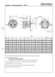
4.3. Dime<strong>ns</strong>io<strong>ns</strong><br />
5. <strong>In</strong>st<strong>al</strong>la<strong>tio</strong>n<br />
All relevant pump dime<strong>ns</strong>io<strong>ns</strong> can be seen <strong>in</strong> the dime<strong>ns</strong>ion sheets of the pumps.<br />
5.1. Place Of <strong>In</strong>st<strong>al</strong>la<strong>tio</strong>n<br />
5.2. Tools<br />
When choos<strong>in</strong>g the place of <strong>in</strong>st<strong>al</strong>la<strong>tio</strong>n make sure there is enough space around the pump for easy<br />
ma<strong>in</strong>ta<strong>in</strong><strong>in</strong>g.<br />
The place of <strong>in</strong>st<strong>al</strong>la<strong>tio</strong>n must be dry. Do not mount <strong>in</strong> aggressive environment.<br />
For mount<strong>in</strong>g our gear pumps you need:<br />
A wrench for the pip<strong>in</strong>g<br />
A wrench or r<strong>in</strong>g wrench for the mount<strong>in</strong>g screws<br />
Allan key for the coupl<strong>in</strong>g<br />
Page 9 / 18<br />
Pum<strong>pe</strong>nfabrik Er<strong>ns</strong>t Scherz<strong>in</strong>ger GmbH & Co. KG • Bregstr. 23-25 • 78120 Furtwangen/ Germany<br />
Phone.: +49 (0) 77 23 – 65 06-0 • Fax: 65 06-40 • E-Mail: <strong>in</strong>fo@scherz<strong>in</strong>ger.de
Rotary Gear Pumps 51 - 551<br />
5.3. <strong>In</strong>iti<strong>al</strong> <strong>In</strong>st<strong>al</strong>la<strong>tio</strong>n<br />
5.3.1. Check Before <strong>In</strong>st<strong>al</strong>la<strong>tio</strong>n<br />
First check the pump for t<strong>ra</strong><strong>ns</strong>porta<strong>tio</strong>n damages (se sec<strong>tio</strong>n 3.2).<br />
Verify the follow<strong>in</strong>g <strong>in</strong>forma<strong>tio</strong>n, some items may not <strong>pe</strong>rta<strong>in</strong> to your pump model:<br />
Liquid to be pum<strong>pe</strong>d<br />
Pump data (flow <strong>ra</strong>te, pressure rise, motor <strong>pe</strong>rformance)<br />
Pump model and ty<strong>pe</strong><br />
Direc<strong>tio</strong>n of rota<strong>tio</strong>n and posi<strong>tio</strong>n of <strong>in</strong>let and outlet ports<br />
Ty<strong>pe</strong> of Shaft Se<strong>al</strong><br />
Addi<strong>tio</strong>n<strong>al</strong> B<strong>al</strong>l Bear<strong>in</strong>g for shaft<br />
WARNING<br />
If there are differences between the pump required and the pump received please contact the manufacturer<br />
prior to start<strong>in</strong>g the pump.<br />
5.3.2. Pump With Motor<br />
When choos<strong>in</strong>g a place for <strong>in</strong>st<strong>al</strong>la<strong>tio</strong>n, be sure the motor-pump unit is mounted on an even surface. If<br />
necessary, use spacers near the mount<strong>in</strong>g bolts 1 to e<strong>ns</strong>ure the unit is level.<br />
WARNING<br />
WARNING<br />
WARNING<br />
If you do not level the pump, mechanic<strong>al</strong> stress may damage the motor or the pump or at least cause<br />
m<strong>al</strong>func<strong>tio</strong><strong>ns</strong>. Tighten the mount<strong>in</strong>g screws carefully 2 after hav<strong>in</strong>g leveled the pump.<br />
Make sure the unit is pro<strong>pe</strong>r ventilated to avoid overheat<strong>in</strong>g of the motor.<br />
Avoid mount<strong>in</strong>g the pump with the pump head down. <strong>In</strong> this case the lip se<strong>al</strong> is bad lubricated and may fail.<br />
figure 5.1<br />
1 2<br />
The four mount<strong>in</strong>g screws 2 are not <strong>in</strong> the sco<strong>pe</strong> of supply.<br />
5.3.3. Pumps For Foot Mount<strong>in</strong>g<br />
a) Pump with coupl<strong>in</strong>g on base plate<br />
While assembl<strong>in</strong>g pump and motor make sure pump shaft and motor shaft are <strong>al</strong>igned well. There must be no<br />
<strong>ra</strong>di<strong>al</strong> or axi<strong>al</strong> forces on both shafts. This can be avoided by us<strong>in</strong>g a flexible shaft coupl<strong>in</strong>g. Coupl<strong>in</strong>gs of this<br />
ty<strong>pe</strong> are available at Scherz<strong>in</strong>ger.<br />
Align<strong>in</strong>g of pump and motor has to be done before connect<strong>in</strong>g the pip<strong>in</strong>g (figure 5.2). The mount<strong>in</strong>g bases of<br />
pump and motor must be par<strong>al</strong>lel. For adjust<strong>in</strong>g the height of the shaft, see dime<strong>ns</strong>ion sheets of pump and<br />
motor.<br />
1. Bolt down the motor (usu<strong>al</strong>ly the more weighty component) with <strong>al</strong>l four screws 1.<br />
2. Fix the coupl<strong>in</strong>g parts with the stud screws to the shafts.<br />
3. Align the pump roughly.<br />
4. Screw <strong>in</strong> the fix<strong>in</strong>g screws 2 for the pump. Pump must be easily to move.<br />
5. Turn drive shaft slowly (through fan shroud 3 or by turn<strong>in</strong>g the coupl<strong>in</strong>g on motor shaft 4) pump <strong>al</strong>ig<strong>ns</strong><br />
now.<br />
Page 10 / 18<br />
Pum<strong>pe</strong>nfabrik Er<strong>ns</strong>t Scherz<strong>in</strong>ger GmbH & Co. KG • Bregstr. 23-25 • 78120 Furtwangen/ Germany<br />
Phone.: +49 (0) 77 23 – 65 06-0 • Fax: 65 06-40 • E-Mail: <strong>in</strong>fo@scherz<strong>in</strong>ger.de
Rotary Gear Pumps 51 - 551<br />
6. Tighten screws 2. Make sure the pump does not move while do<strong>in</strong>g this.<br />
The axi<strong>al</strong> clea<strong>ra</strong>nce between the shaft ends must be determ<strong>in</strong>ed by the supplier of the coupl<strong>in</strong>g.<br />
WARNING<br />
To gua<strong>ra</strong>ntee both units are <strong>al</strong>igned pro<strong>pe</strong>rly some ex<strong>pe</strong>rience is required. Is the <strong>al</strong>ignment is done badly, the<br />
force on the shaft ends and the wear will be <strong>in</strong>creased. The pump may fail.<br />
5 4 3<br />
2 1<br />
figure 5.2<br />
After assembly of the coupl<strong>in</strong>g, it is requested to protect the coupl<strong>in</strong>g e.g. by a coupl<strong>in</strong>g guard - see figure 5.2<br />
- 5 - aga<strong>in</strong>st touch<strong>in</strong>g.<br />
b) Mount<strong>in</strong>g a pump driven by a belt drive<br />
figure 5.3<br />
Driv<strong>in</strong>g pumps with a V-Belt Drive, Flat Belt Drive or multiple belt<br />
drive is only possible with pumps with an addi<strong>tio</strong>n<strong>al</strong> B<strong>al</strong>l Bear<strong>in</strong>g<br />
for the shaft end (see sec<strong>tio</strong>n 4.2.4 - figure 4.14 and addi<strong>tio</strong>n<strong>al</strong><br />
explana<strong>tio</strong>n). When c<strong>al</strong>culat<strong>in</strong>g and choos<strong>in</strong>g the belt drive,<br />
check the max. shaft end load of the used pump model.<br />
The pulley must be centered on the feather key (figure 5.3) and<br />
fixed safely. The more the pulley is shifted to the shaft end, the<br />
higher the bear<strong>in</strong>g load and the less is the possible <strong>ra</strong>di<strong>al</strong><br />
bear<strong>in</strong>g load.<br />
After assembly, protect<strong>in</strong>g the belt drive by a guard aga<strong>in</strong>st touch<strong>in</strong>g is absolutely necessary.<br />
5.3.4. Mount<strong>in</strong>g C - Face Pumps (F - Version)<br />
The way of mount<strong>in</strong>g of c-face pumps differs with the applica<strong>tio</strong>n. A descrip<strong>tio</strong>n how this pump has to be<br />
<strong>in</strong>st<strong>al</strong>led cannot be made. If you need help <strong>in</strong> your s<strong>pe</strong>ci<strong>al</strong> case of <strong>in</strong>st<strong>al</strong>la<strong>tio</strong>n, do not hesitate to contact<br />
Scherz<strong>in</strong>ger Pumps.<br />
5.3.5. Motor Assembly Of C – Face Pumps (ZK - Version)<br />
The delivered shaft coupl<strong>in</strong>g can be either co<strong>ns</strong>ist<strong>in</strong>g of two parts (see figure 5.4) that will be fixed to the shaft<br />
ends or three parts (see figure 5.5) with a flexible com<strong>pe</strong><strong>ns</strong>at<strong>in</strong>g element.<br />
Page 11 / 18<br />
Pum<strong>pe</strong>nfabrik Er<strong>ns</strong>t Scherz<strong>in</strong>ger GmbH & Co. KG • Bregstr. 23-25 • 78120 Furtwangen/ Germany<br />
Phone.: +49 (0) 77 23 – 65 06-0 • Fax: 65 06-40 • E-Mail: <strong>in</strong>fo@scherz<strong>in</strong>ger.de
Rotary Gear Pumps 51 - 551<br />
figure 5.4<br />
figure 5.5<br />
The coupl<strong>in</strong>g <strong>in</strong>clud<strong>in</strong>g the set screws are <strong>in</strong>cluded. The coupl<strong>in</strong>g part of the pump is mounted <strong>in</strong> the correct<br />
posi<strong>tio</strong>n (figure 5.6 - length a). To mount the motor to the pump do as follows:<br />
1. Attach motor coupl<strong>in</strong>g 1 <strong>in</strong> distance b to the drive shaft.<br />
2. Fix coupl<strong>in</strong>g part with set screw 2 to shaft.<br />
3. Put motor 3 on fan shroud (shaft side up).<br />
4. If needed, put flexible com<strong>pe</strong><strong>ns</strong>at<strong>in</strong>g element to the coupl<strong>in</strong>g part.<br />
5. Attach pump with c-face flange 4 to the motor 3 (It may be helpful to turn the pump slightly).<br />
6. Fix pump with Screws 5 (not <strong>in</strong> sco<strong>pe</strong> of delivery) to the motor.<br />
1<br />
figure 5.6<br />
4 6 2 5 3<br />
Please use the follow<strong>in</strong>g table to determ<strong>in</strong>e the dime<strong>ns</strong>io<strong>ns</strong> of a and b <strong>in</strong> mm. All measures are v<strong>al</strong>id for ISO<br />
motors, IMB 34 (tole<strong>ra</strong>nces due to ISO 7168):<br />
Pump Size<br />
Motor<br />
Motor<br />
a b Pump Size<br />
Size<br />
Size<br />
a b<br />
51 63 *) *) 151 71 6 -4<br />
51 71 *) *) 151 80 5,5 -3,5<br />
51 0,25 *) *) 251 71 1 0<br />
76 63 *) *) 251 80 5 3<br />
76 71 *) *) 251 90 2 -2<br />
101 63 *) *) 351 80 2 3<br />
101 71 6 -4 351 90 2 3<br />
101 80 5,5 -3,5 351 100 *) *)<br />
451 80 2 0 551 90 *) *)<br />
451 90 3 3 551 100 *) *)<br />
451 100 *) *) 551 112 *) *)<br />
*) upon request<br />
5.3.6. Electric Connec<strong>tio</strong>n<br />
Motor connec<strong>tio</strong><strong>ns</strong> should be done <strong>in</strong> accordance with loc<strong>al</strong> laws and legisla<strong>tio</strong>n. Also pay atten<strong>tio</strong>n to the<br />
o<strong>pe</strong><strong>ra</strong>t<strong>in</strong>g <strong>in</strong>s<strong>tru</strong>c<strong>tio</strong><strong>ns</strong> of the motor.<br />
To receive the maximum motor torque, <strong>al</strong>ways use a delta connec<strong>tio</strong>n.<br />
Page 12 / 18<br />
Pum<strong>pe</strong>nfabrik Er<strong>ns</strong>t Scherz<strong>in</strong>ger GmbH & Co. KG • Bregstr. 23-25 • 78120 Furtwangen/ Germany<br />
Phone.: +49 (0) 77 23 – 65 06-0 • Fax: 65 06-40 • E-Mail: <strong>in</strong>fo@scherz<strong>in</strong>ger.de
Rotary Gear Pumps 51 - 551<br />
5.3.7. Pip<strong>in</strong>g<br />
It is very important to <strong>in</strong>st<strong>al</strong>l correct fitt<strong>in</strong>gs to the pump. All fitt<strong>in</strong>gs should screw together easily, use force<br />
only for f<strong>in</strong><strong>al</strong> seat.<br />
WARNING<br />
Avoid pi<strong>pe</strong> connec<strong>tio</strong><strong>ns</strong> that place any extern<strong>al</strong> st<strong>ra</strong><strong>in</strong>s or loads on the pump.<br />
The pip<strong>in</strong>g must have a suitable <strong>in</strong>ner diameter. The m<strong>in</strong>imum diameter is the nom<strong>in</strong><strong>al</strong> widthof the pump<br />
connec<strong>tio</strong><strong>ns</strong>. On the suc<strong>tio</strong>n side of the pump, we recommend pip<strong>in</strong>g one size larger than the nom<strong>in</strong><strong>al</strong> width<br />
of the pressure side. As direc<strong>tio</strong>n<strong>al</strong> quantity we recommend follow<strong>in</strong>g maximum flow velocities <strong>in</strong> the pip<strong>in</strong>g.<br />
Up to 200 mm²/s Up to 600 mm²/s Up to 2000 mm²/s<br />
Suc<strong>tio</strong>n Pip<strong>in</strong>g 1,5 m / s 1,0 m / s 0,5 m / s<br />
Discharge Pip<strong>in</strong>g 3,0 m / s 2,0 m / s 1,0 m / s<br />
WARNING<br />
To protect the pump from damage caused by solids <strong>in</strong> the liquid, we recommend a 50-micron filter <strong>in</strong> the<br />
suc<strong>tio</strong>n pip<strong>in</strong>g. Be sure the filter does not cause a serious pressure drop.<br />
Suc<strong>tio</strong>n pip<strong>in</strong>g should be as st<strong>ra</strong>ight and direct as possible to the pump with a m<strong>in</strong>imum number of elbows.<br />
We recommend us<strong>in</strong>g long <strong>ra</strong>dius elbow ty<strong>pe</strong>.<br />
The suc<strong>tio</strong>n pi<strong>pe</strong> should have a cont<strong>in</strong>uous rise to the pump. If it is necessary to <strong>in</strong>st<strong>al</strong>l the pip<strong>in</strong>g ris<strong>in</strong>g and<br />
descend<strong>in</strong>g, there must be a provision to purge air at the highest po<strong>in</strong>ts of the pip<strong>in</strong>g.<br />
WARNING<br />
After <strong>in</strong>st<strong>al</strong>l<strong>in</strong>g the pip<strong>in</strong>g, be sure it is free of sediments and chips. Otherwise the pump may be damaged.<br />
If the suc<strong>tio</strong>n head will be greater than 4 meters, we recommend <strong>in</strong>st<strong>al</strong>l<strong>in</strong>g a check v<strong>al</strong>ve <strong>in</strong> the suc<strong>tio</strong>n pip<strong>in</strong>g.<br />
Please contact the manufacturer for suc<strong>tio</strong>n st<strong>ra</strong><strong>in</strong>ers with an <strong>in</strong>teg<strong>ra</strong>ted check v<strong>al</strong>ve <strong>in</strong> various sizes.<br />
Gear pumps must not o<strong>pe</strong><strong>ra</strong>te aga<strong>in</strong>st closed v<strong>al</strong>ves or a system closed to its discharge side. The pump can<br />
create a hazardous pressure rise, which can system environment<strong>al</strong> damage. We recommend a pump with an<br />
<strong>in</strong>teg<strong>ra</strong>ted relief v<strong>al</strong>ve, or a relief v<strong>al</strong>ve <strong>in</strong>st<strong>al</strong>led directly <strong>in</strong> the discharge pi<strong>pe</strong> of the pump.<br />
<strong>In</strong> situa<strong>tio</strong><strong>ns</strong> where de-ae<strong>ra</strong>t<strong>in</strong>g is a critic<strong>al</strong> process, the <strong>in</strong>st<strong>al</strong>la<strong>tio</strong>n of isolat<strong>in</strong>g v<strong>al</strong>ves, located directly before<br />
the <strong>in</strong>let port and directly after discharge port is recommended. This <strong>al</strong>lows for remov<strong>al</strong> of the pump without<br />
d<strong>ra</strong><strong>in</strong><strong>in</strong>g the complete system.<br />
Pi<strong>pe</strong>s should be screwed together and not leak, otherwise air may <strong>pe</strong>net<strong>ra</strong>te <strong>in</strong>to the pump, which will prevent<br />
the pump from suck<strong>in</strong>g, or on the discharge side the liquid could drop out.<br />
It may be necessary to <strong>in</strong>teg<strong>ra</strong>te silencers <strong>in</strong> the pip<strong>in</strong>g.<br />
6. Start Up / Shut Down<br />
6.1. Prepare For O<strong>pe</strong><strong>ra</strong><strong>tio</strong>n<br />
After complete <strong>in</strong>st<strong>al</strong>la<strong>tio</strong>n, before start up check the pump and the environment by follow<strong>in</strong>g ques<strong>tio</strong><strong>ns</strong>:<br />
Is it possible to turn the pump by hand (sm<strong>al</strong>l pumps) or with a tool (big pump)?<br />
Are suc<strong>tio</strong>n and pressure pip<strong>in</strong>g connected correctly?<br />
Do pump and drive have the same direc<strong>tio</strong>n of rota<strong>tio</strong>n?<br />
Is the time of dry runn<strong>in</strong>g restricted to a m<strong>in</strong>imum?<br />
Are the pump <strong>in</strong>tern<strong>al</strong>s wetted with the liquid to be pum<strong>pe</strong>d if the pump has to prime (max. dry runn<strong>in</strong>g<br />
time 20 sec.)?<br />
are check v<strong>al</strong>ves, v<strong>al</strong>ves <strong>in</strong> <strong>rig</strong>ht posi<strong>tio</strong>n?<br />
Are the pi<strong>pe</strong>s checked for leakage?<br />
Is it possible to stop the pump by an emergency switch <strong>in</strong> case of m<strong>al</strong>func<strong>tio</strong>n?<br />
Is enough liquid <strong>in</strong> the reservoir?<br />
If tem<strong>pe</strong><strong>ra</strong>ture of pumps and liquid differ more than 50°C the pump has to be adapted <strong>in</strong> tem<strong>pe</strong><strong>ra</strong>ture!<br />
Are <strong>al</strong>l rotat<strong>in</strong>g parts protected aga<strong>in</strong>st touch<strong>in</strong>g?<br />
6.2. Start Up<br />
WARNING<br />
Flush the system and the pump head with the liquid to be pum<strong>pe</strong>d.<br />
Adjust relief v<strong>al</strong>ve to wanted pressure accord<strong>in</strong>g to sec<strong>tio</strong>n 6.3.<br />
Dry runn<strong>in</strong>g time should not extend 20 seconds.<br />
Page 13 / 18<br />
Pum<strong>pe</strong>nfabrik Er<strong>ns</strong>t Scherz<strong>in</strong>ger GmbH & Co. KG • Bregstr. 23-25 • 78120 Furtwangen/ Germany<br />
Phone.: +49 (0) 77 23 – 65 06-0 • Fax: 65 06-40 • E-Mail: <strong>in</strong>fo@scherz<strong>in</strong>ger.de
Rotary Gear Pumps 51 - 551<br />
6.3. Relief V<strong>al</strong>ve<br />
With the <strong>in</strong>teg<strong>ra</strong>ted relief v<strong>al</strong>ve it is possible to determ<strong>in</strong>e the relative pressure rise to exact v<strong>al</strong>ue (see sec<strong>tio</strong>n<br />
4.2.3).<br />
All relief v<strong>al</strong>ves are tested to e<strong>ns</strong>ure they are <strong>in</strong> good work<strong>in</strong>g condi<strong>tio</strong>n. Relief v<strong>al</strong>ves are not set at a s<strong>pe</strong>cific<br />
v<strong>al</strong>ue, unless requested by the customer.<br />
The relief v<strong>al</strong>ve should be set while the pump is o<strong>pe</strong><strong>ra</strong>t<strong>in</strong>g. Measure the pressure on the outlet side of the<br />
pump. Pay atten<strong>tio</strong>n to do the adjustment with the correct o<strong>pe</strong><strong>ra</strong>t<strong>in</strong>g condi<strong>tio</strong><strong>ns</strong>:<br />
Flow Rate<br />
Tem<strong>pe</strong><strong>ra</strong>ture<br />
System Pressure<br />
S<strong>pe</strong>ed of Rota<strong>tio</strong>n<br />
Correct V<strong>al</strong>ve Spr<strong>in</strong>g<br />
Two different v<strong>al</strong>ve ty<strong>pe</strong>s are available: (figure 6.1 and figure 6.2)<br />
1 2 3 4 5 6 7 8 9<br />
figure 6.1 – relief v<strong>al</strong>ves of pump ty<strong>pe</strong>s 101, 151 and 251<br />
Adjust<strong>in</strong>g V<strong>al</strong>ves of the Ty<strong>pe</strong>s 101, 151 and 251<br />
1. U<strong>ns</strong>crew plug screw 1 and remove se<strong>al</strong> 2<br />
2. Adjust the relief v<strong>al</strong>ve by turn<strong>in</strong>g the adjust<strong>in</strong>g screw 2 with an Allan key<br />
• To the left (counter clockwise) => decreas<strong>in</strong>g the c<strong>ra</strong>ck pressure<br />
• To the <strong>rig</strong>ht (clockwise) => <strong>in</strong>creas<strong>in</strong>g the c<strong>ra</strong>ck pressure<br />
• Scherz<strong>in</strong>ger recommends to set the c<strong>ra</strong>ck pressure about 20% higher than the needed pressure<br />
rise<br />
3. Replace plug screw 1 and se<strong>al</strong> 2 and tighten both<br />
1 2 3 4 5 6 7 8 9<br />
figure 6.2 - relief v<strong>al</strong>ves of pump ty<strong>pe</strong>s 51, 76, 351, 451 and 551<br />
Adjust<strong>in</strong>g V<strong>al</strong>ves of the Ty<strong>pe</strong>s 51, 76, 351, 451 and 551<br />
1. U<strong>ns</strong>crew and remove cap screw 1 and o<strong>pe</strong>n counter nut 5<br />
2. Adjust the relief v<strong>al</strong>ve by turn<strong>in</strong>g the adjust<strong>in</strong>g screw 2 with a screw driver<br />
• To the left (counter clockwise) => decreas<strong>in</strong>g the c<strong>ra</strong>ck pressure<br />
• To the <strong>rig</strong>ht (clockwise) => <strong>in</strong>creas<strong>in</strong>g the c<strong>ra</strong>ck pressure<br />
• Scherz<strong>in</strong>ger recommends to set the c<strong>ra</strong>ck pressure about 20% higher than the needed pressure<br />
rise<br />
Page 14 / 18<br />
Pum<strong>pe</strong>nfabrik Er<strong>ns</strong>t Scherz<strong>in</strong>ger GmbH & Co. KG • Bregstr. 23-25 • 78120 Furtwangen/ Germany<br />
Phone.: +49 (0) 77 23 – 65 06-0 • Fax: 65 06-40 • E-Mail: <strong>in</strong>fo@scherz<strong>in</strong>ger.de
Rotary Gear Pumps 51 - 551<br />
3. Tighten counter nut 5 to fix the adjust<strong>in</strong>g screw<br />
4. Replace and tighten cap screw 1<br />
5. Make sure <strong>al</strong>l se<strong>al</strong>s 4 are rear<strong>ra</strong>nged correctly<br />
While cap screw (plug screw) 1 is o<strong>pe</strong>ned, a sm<strong>al</strong>l amount of leakage is possible.<br />
WARNING<br />
The relief v<strong>al</strong>ve is designed for a short-term overload protec<strong>tio</strong>n. Pump<strong>in</strong>g liquid through a relief v<strong>al</strong>ve will<br />
gene<strong>ra</strong>te heat <strong>in</strong> the liquid. For applica<strong>tio</strong>n at ambient o<strong>pe</strong><strong>ra</strong>t<strong>in</strong>g tem<strong>pe</strong><strong>ra</strong>tures, if the relief v<strong>al</strong>ve is o<strong>pe</strong>ned<br />
more than 3 m<strong>in</strong>utes, damage to the pump head could occur. The higher the o<strong>pe</strong><strong>ra</strong>t<strong>in</strong>g tem<strong>pe</strong><strong>ra</strong>ture, the<br />
shorter the possible relief v<strong>al</strong>ve o<strong>pe</strong>n<strong>in</strong>g time.<br />
WARNING: do not remove adjust<strong>in</strong>g screw while pump is <strong>in</strong> o<strong>pe</strong><strong>ra</strong><strong>tio</strong>n or the system is under pressure. Liquid<br />
can spurt out and cause <strong>pe</strong>rson<strong>al</strong> <strong>in</strong>juries!!<br />
6.4. Monitor<strong>in</strong>g<br />
WARNING<br />
6.5. Shut – Down<br />
6.6. Dismount<strong>in</strong>g<br />
We recommend <strong>in</strong>st<strong>al</strong>l<strong>in</strong>g a manometer on the outlet side of the pump to check the o<strong>pe</strong><strong>ra</strong>t<strong>in</strong>g pressure. If the<br />
o<strong>pe</strong><strong>ra</strong>t<strong>in</strong>g tem<strong>pe</strong><strong>ra</strong>ture is greater than 80°C we recom mend <strong>in</strong>st<strong>al</strong>l<strong>in</strong>g a tem<strong>pe</strong><strong>ra</strong>ture gauge. Tem<strong>pe</strong><strong>ra</strong>tures<br />
greater than 80°C (Buna N) or 160°C (Viton) may destr oy the se<strong>al</strong>s or damage the magnets (with magnetic<br />
coupl<strong>in</strong>g).<br />
Reduce the s<strong>pe</strong>ed of rota<strong>tio</strong>n, if possible, to h<strong>al</strong>f o<strong>pe</strong><strong>ra</strong>t<strong>in</strong>g s<strong>pe</strong>ed.<br />
D<strong>ra</strong><strong>in</strong> the pump head by reduc<strong>in</strong>g the outlet pressure to atmospheric pressure and remove the suc<strong>tio</strong>n<br />
pip<strong>in</strong>g out of the liquid tank so that the pump sucks air (not if the system is under pressure).<br />
Be sure the pump does not run dry for more than 30 seconds.<br />
If you are pump<strong>in</strong>g noxious liquids, flush the pump with a neutr<strong>al</strong>iz<strong>in</strong>g liquid.<br />
Flush the pump with lubrica<strong>tio</strong>n oil (e.g. Shell GF68).<br />
Switch off drive motor and remove electric connec<strong>tio</strong><strong>ns</strong>. Make sure <strong>al</strong>l steps <strong>in</strong> sec<strong>tio</strong>n 6.5 have been<br />
completed.<br />
Remove the pump<br />
7. Ma<strong>in</strong>tenance<br />
7.1. Gener<strong>al</strong> <strong>In</strong>forma<strong>tio</strong>n<br />
Be sure that the pump head is cleaned with a non-toxic liquid. <strong>In</strong> the event the pump head was o<strong>pe</strong><strong>ra</strong>t<strong>in</strong>g with<br />
dangerous or noxious liquids, use necessary safety precau<strong>tio</strong><strong>ns</strong>.<br />
7.2. <strong>In</strong>s<strong>pe</strong>c<strong>tio</strong>n<br />
7.3. Repair Work<br />
WARNING<br />
7.4. Tools<br />
All <strong>in</strong>tern<strong>al</strong> bush<strong>in</strong>gs are sleeve bear<strong>in</strong>gs, lubricated by the pum<strong>pe</strong>d liquid. Only one pump version (see<br />
sec<strong>tio</strong>n 4.2.4 - figure 4.14) is equip<strong>pe</strong>d with an addi<strong>tio</strong>n<strong>al</strong> b<strong>al</strong>l bear<strong>in</strong>g at the shaft end. Also for this ty<strong>pe</strong> no<br />
ma<strong>in</strong>tenance is necessary.<br />
If the pump head has been disassembled, it is necessary to replace <strong>al</strong>l O–r<strong>in</strong>gs to e<strong>ns</strong>ure a pro<strong>pe</strong>r se<strong>al</strong>.<br />
An exact descrip<strong>tio</strong>n of the ma<strong>in</strong>tenance steps can, due to the various pump ty<strong>pe</strong>s, not be supplied.<br />
Please co<strong>ns</strong>ult the match<strong>in</strong>g spare part list.<br />
For ma<strong>in</strong>tenance you will need:<br />
Allan key 2 to 10mm<br />
Wrench 8 to 40 mm<br />
Dynamometric key (3 to 40 Nm)<br />
pliers for reta<strong>in</strong><strong>in</strong>g r<strong>in</strong>gs for shafts and bores (DIN471 / 472)<br />
p<strong>in</strong>cers to remove the feather keys<br />
tool to press <strong>in</strong> the lip se<strong>al</strong> r<strong>in</strong>gs<br />
Page 15 / 18<br />
Pum<strong>pe</strong>nfabrik Er<strong>ns</strong>t Scherz<strong>in</strong>ger GmbH & Co. KG • Bregstr. 23-25 • 78120 Furtwangen/ Germany<br />
Phone.: +49 (0) 77 23 – 65 06-0 • Fax: 65 06-40 • E-Mail: <strong>in</strong>fo@scherz<strong>in</strong>ger.de
Decla<strong>ra</strong><strong>tio</strong>n of conformity accord<strong>in</strong>g to<br />
directive 2006/42/EC<br />
The follow<strong>in</strong>g pump and accessories sent for <strong>in</strong>s<strong>pe</strong>c<strong>tio</strong>n or repair <strong>in</strong> conjunc<strong>tio</strong>n with this Safety Decla<strong>ra</strong><strong>tio</strong>n:<br />
Ty<strong>pe</strong> Pump number Delivery date<br />
Reason for the repair order<br />
Reason (cont<strong>in</strong>ued)<br />
O<br />
O<br />
was not used with hazardous liquids<br />
came <strong>in</strong>to contact with hazardous liquids or liquids that require label<strong>in</strong>g<br />
<strong>in</strong>dicate most recent pum<strong>pe</strong>d liquid<br />
The pump has been carefully emptied and cleaned <strong>in</strong>side and out before be<strong>in</strong>g ship<strong>pe</strong>d/provided. Clean<strong>in</strong>g was <strong>pe</strong>rformed <strong>in</strong><br />
accordance with the relevant o<strong>pe</strong><strong>ra</strong>t<strong>in</strong>g <strong>in</strong>s<strong>tru</strong>c<strong>tio</strong><strong>ns</strong>.<br />
O S<strong>pe</strong>ci<strong>al</strong> safety precau<strong>tio</strong><strong>ns</strong> are not necessary when handl<strong>in</strong>g the pump.<br />
O The follow<strong>in</strong>g safety precau<strong>tio</strong><strong>ns</strong> are necessary for the flush<strong>in</strong>g liquids<br />
and dispos<strong>al</strong>:<br />
We provide our assu<strong>ra</strong>nce that the <strong>in</strong>forma<strong>tio</strong>n provided above is correct and complete and that shipment has been <strong>pe</strong>rformed<br />
<strong>in</strong> accordance with leg<strong>al</strong> stipula<strong>tio</strong><strong>ns</strong>.<br />
Company<br />
Name<br />
Street<br />
Posi<strong>tio</strong>n<br />
City<br />
Telephone<br />
Country<br />
Fax<br />
Date<br />
Company stamp/signature<br />
For safety reaso<strong>ns</strong>, pumps delivered without a completed Safety Decla<strong>ra</strong><strong>tio</strong>n can be neither <strong>in</strong>s<strong>pe</strong>cted nor repaired.<br />
Page 16 / 18<br />
Pum<strong>pe</strong>nfabrik Er<strong>ns</strong>t Scherz<strong>in</strong>ger GmbH & Co. KG • Bregstr. 23-25 • 78120 Furtwangen/ Germany<br />
Phone.: +49 (0) 77 23 – 65 06-0 • Fax: 65 06-40 • E-Mail: <strong>in</strong>fo@scherz<strong>in</strong>ger.de
Decla<strong>ra</strong><strong>tio</strong>n of conformity accord<strong>in</strong>g to<br />
directive 2006/42/EC<br />
Decla<strong>ra</strong><strong>tio</strong>n of conformity accord<strong>in</strong>g to<br />
directive 2006/42/EC (mach<strong>in</strong>ery directive)<br />
For the purposes of EC directive 2006/42/EC, Annex II A of May 17, 2006, the manufacturer<br />
declares that the product<br />
Pum<strong>pe</strong>nfabrik Er<strong>ns</strong>t Scherz<strong>in</strong>ger GmbH & Co. KG<br />
Bregst<strong>ra</strong>sse 23-25<br />
D – 78120 Furtwangen / Germany<br />
Ty<strong>pe</strong>:<br />
Gear pump<br />
Series:<br />
51 – 551 AR, AL, BR, BL, C/SR, C/SL<br />
51 – 551 FAR, FAL, FBR, FBL, FC/SR, FC/SL<br />
51 – 551 FA/ ZK..., FAL/ZK..., FB/ZK..., FBL/ZK...<br />
51 – 551 FC/SR/ZK..., FC/SL/ZK...<br />
51 – 551 FA/ M..., FAL/M..., FB/M..., FBL/M...<br />
51 – 551 FC/SR/M..., FC/SL/M...<br />
is delivered without an electric drive mach<strong>in</strong>e and thereby complies with the stipula<strong>tio</strong><strong>ns</strong> of directive 2006/42/EC,<br />
Annex I, No. 1.<br />
Applied directives:<br />
2006/42/EC<br />
2006/95/EC<br />
2004/108/EC<br />
Mach<strong>in</strong>ery directive<br />
Low voltage directive<br />
Electromagnetic compatibility (EMC directive)<br />
Applied harmonized standards:<br />
EN ISO 12100 T1 EN ISO 13857 EN 809<br />
EN ISO 12100 T2 EN ISO 13732-1 EN 60204 T1<br />
Applied na<strong>tio</strong>n<strong>al</strong> technic<strong>al</strong> standards and s<strong>pe</strong>cifica<strong>tio</strong><strong>ns</strong>:<br />
Documenta<strong>tio</strong>n manager:<br />
UVV<br />
Erich Willimsky<br />
Pum<strong>pe</strong>nfabrik Er<strong>ns</strong>t Scherz<strong>in</strong>ger GmbH & Co. KG<br />
Bregst<strong>ra</strong>sse 23-25<br />
D – 78120 Furtwangen / Germany<br />
Furtwangen, 10.11.2010<br />
(Dipl.-<strong>In</strong>g. Erich Willimsky)<br />
Manag<strong>in</strong>g Director<br />
Page 17 / 18<br />
Pum<strong>pe</strong>nfabrik Er<strong>ns</strong>t Scherz<strong>in</strong>ger GmbH & Co. KG • Bregstr. 23-25 • 78120 Furtwangen/ Germany<br />
Phone.: +49 (0) 77 23 – 65 06-0 • Fax: 65 06-40 • E-Mail: <strong>in</strong>fo@scherz<strong>in</strong>ger.de
Rotary Gear Pumps 51 - 551<br />
Notes<br />
Page 18 / 18<br />
Pum<strong>pe</strong>nfabrik Er<strong>ns</strong>t Scherz<strong>in</strong>ger GmbH & Co. KG • Bregstr. 23-25 • 78120 Furtwangen/ Germany<br />
Phone.: +49 (0) 77 23 – 65 06-0 • Fax: 65 06-40 • E-Mail: <strong>in</strong>fo@scherz<strong>in</strong>ger.de