cuber model ac 56 - Scotsman
cuber model ac 56 - Scotsman
cuber model ac 56 - Scotsman

Create successful ePaper yourself
Turn your PDF publications into a flip-book with our unique Google optimized e-Paper software.
Page 1<br />
Page 1<br />
SERVICE MANUAL<br />
AC 46<br />
AC <strong>56</strong><br />
AC 86<br />
Cubers<br />
with storage<br />
SCOTSMAN EUROPE - FRIMONT SPA<br />
Via Puccini, 22 - 20010 Pogliano M.se - Milano - Italy<br />
Tel. +39-02-93960.1 (Aut. Sel.)- Telefax +39-02-93550500<br />
Direct Line to Service & Parts:<br />
Phone +39-02-93960350 - Fax +39-02-93540449<br />
Website: www.scotsman-ice.com<br />
E-Mail: scotsman.europe@frimont.it<br />
ISO 9001 - Cert. n. 0080<br />
MS 1000.86 REV. 10/2008
Page 2<br />
Page 2<br />
INDICE<br />
Table of contents<br />
Specifications AC 46<br />
Specifications AC <strong>56</strong><br />
Specifications AC 86<br />
page<br />
2<br />
3<br />
5<br />
7<br />
GENERAL INFORMATION AND INSTALLATION<br />
Introduction<br />
Unp<strong>ac</strong>king and Inspection<br />
Location and levelling<br />
Electrical connections<br />
Water supply and drain connections<br />
Final check list<br />
Installation pr<strong>ac</strong>tice<br />
9<br />
9<br />
9<br />
9<br />
10<br />
10<br />
11<br />
OPERATING INSTRUCTIONS<br />
Start up<br />
Operational checks<br />
12<br />
12<br />
OPERATING PRINCIPLES (How it works)<br />
Freezing cycle<br />
Harvest cycle<br />
Electrical sequence<br />
Components description<br />
13<br />
13<br />
15<br />
15<br />
ADJUSTMENT, REMOVAL AND REPLACEMENT PROCEDURES<br />
Adjustment of the cube size<br />
Wiring diagram<br />
Service diagnosis<br />
18<br />
19<br />
22<br />
MAINTENANCE AND CLEANING INSTRUCTIONS<br />
General<br />
Icemaker<br />
Clean - Repl<strong>ac</strong>e of air condenser filter<br />
Cleaning instructions of water system<br />
24<br />
24<br />
24<br />
24
Page 3<br />
Page 3<br />
SPECIFICATIONS<br />
CUBER MODEL AC 46<br />
Important operating requirements:<br />
MIN.<br />
Air temperature 10°C<br />
Water temperature 5°C<br />
Water pressure 1 bar<br />
Electr. voltage variations<br />
from voltage rating<br />
specified<br />
on nameplate -10%<br />
MAX.<br />
40°C<br />
35°C<br />
5 bar<br />
+10%<br />
ice making cap<strong>ac</strong>ity<br />
AIR COOLED MODELS<br />
WATER COOLED MODELS<br />
ICE PRODUCED PER 24 HRS.<br />
Kg.<br />
25<br />
24<br />
23<br />
22<br />
21<br />
20<br />
19<br />
18<br />
17<br />
o°C<br />
10<br />
21<br />
32<br />
38<br />
AMBIENT TEMPERATURE<br />
ICE PRODUCED PER 24 HRS.<br />
Kg.<br />
25<br />
24<br />
23<br />
22<br />
21<br />
20<br />
19<br />
18<br />
17<br />
o°C<br />
10<br />
21<br />
32<br />
38<br />
AMBIENT TEMPERATURE<br />
16<br />
32 27 21 15 10<br />
o°C<br />
16<br />
32 27 21 15 10<br />
o°C<br />
WATER TEMPERATURE<br />
°C<br />
°F<br />
WATER TEMPERATURE<br />
NOTE. With the unit in "built-in" conditions, the ice production is gradually reduced in respect to the<br />
levels shown in the graf, up to a maximum of 10% at room temperatures higher than 32°C.<br />
The daily ice-making cap<strong>ac</strong>ity is directly related to the condenser air inlet temperature, water<br />
temperature conditions of the condenser air filter and age of the m<strong>ac</strong>hine.<br />
To keep your SCOTSMAN CUBER at peak performance levels, periodic maintenance checks must<br />
be carried out as indicated on Maintenance and Cleaning section of this manual.
Page 4<br />
Page 4<br />
SPECIFICATIONS<br />
Dimensions:<br />
HEIGHT<br />
WIDTH<br />
DEPTH<br />
WEIGHT<br />
645 mm.<br />
386 mm.<br />
600 mm.<br />
42 Kgs.<br />
AC 46 - CUBER<br />
m<strong>ac</strong>hine specifications<br />
Bin<br />
Model Cond. unit Finish Comp. HP<br />
Cap<strong>ac</strong>ity<br />
AC 46 AS 6<br />
Air<br />
Stainless steel 1/4 9 Kg.<br />
AC 46 WS 6 Water<br />
Water req.<br />
lt/24 HR<br />
77*<br />
350*<br />
Basic electr. Amps<br />
Start<br />
Watts<br />
. Electric power cons.<br />
Nr. of wires Amps fuse<br />
Amps<br />
Kwh per 24 Hr<br />
8<br />
230/50/1 2.1 12 400 3 x 1.5 mm 2 10<br />
6<br />
Cubes per harvest: 18 medium<br />
* A 15°C water temperature
Page 5<br />
Page 5<br />
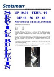
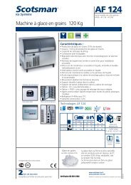
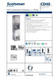
SPECIFICATIONS<br />
CUBER MODEL AC <strong>56</strong><br />
Important operating requirements:<br />
MIN.<br />
Air temperature 10°C<br />
Water temperature 5°C<br />
Water pressure 1 bar<br />
Electr. voltage variations<br />
from voltage rating<br />
specified<br />
on nameplate -10%<br />
MAX.<br />
40°C<br />
35°C<br />
5 bar<br />
+10%<br />
ice making cap<strong>ac</strong>ity<br />
AIR COOLED MODELS<br />
WATER COOLED MODELS<br />
ICE PRODUCED PER 24 HRS.<br />
Kg.<br />
32<br />
30<br />
28<br />
26<br />
24<br />
22<br />
20<br />
o°C<br />
10<br />
21<br />
32<br />
38<br />
AMBIENT TEMPERATURE<br />
ICE PRODUCED PER 24 HRS.<br />
Kg.<br />
33<br />
32<br />
31<br />
30<br />
29<br />
28<br />
27<br />
26<br />
25<br />
24<br />
o°C<br />
10<br />
21<br />
32<br />
38<br />
AMBIENT TEMPERATURE<br />
18<br />
32 27 21 15 10<br />
o°C<br />
23<br />
32 27 21 15 10<br />
o°C<br />
WATER TEMPERATURE<br />
WATER TEMPERATURE<br />
NOTE. With the unit in "built-in" conditions, the ice production is gradually reduced in respect to the<br />
levels shown in the graf, up to a maximum of 10% at room temperatures higher than 32°C.<br />
The daily ice-making cap<strong>ac</strong>ity is directly related to the condenser air inlet temperature, water<br />
temperature conditions of the condenser air filter and age of the m<strong>ac</strong>hine.<br />
To keep your SCOTSMAN CUBER at peak performance levels, periodic maintenance checks must<br />
be carried out as indicated on Maintenance and Cleaning section of this manual.
Page 6<br />
Page 6<br />
SPECIFICATIONS<br />
Dimensions:<br />
HEIGHT<br />
WIDTH<br />
DEPTH<br />
WEIGHT<br />
695 mm.<br />
386 mm.<br />
600 mm.<br />
45 Kgs.<br />
AC <strong>56</strong> - CUBER<br />
m<strong>ac</strong>hine specifications<br />
Model Cond. unit Finish Comp. HP<br />
Bin<br />
Cap<strong>ac</strong>ity<br />
Water req.<br />
lt/24 HR<br />
AC <strong>56</strong> AS 6<br />
AC <strong>56</strong> WS 6<br />
Air<br />
Water<br />
Stainless steel 1/4 12.5 Kg.<br />
0 90 **<br />
270*<br />
Basic electr. Amps<br />
Start<br />
Watts<br />
. Electric power cons.<br />
Nr. of wires Amps fuse<br />
Amps<br />
Kwh per 24 Hr<br />
7.6<br />
230/50/1 2.1 12 400 3 x 1.5 mm 2 10<br />
7<br />
Cubes per harvest: 24 medium<br />
* A 15°C water temperature
Page 7<br />
Page 7<br />
SPECIFICATIONS<br />
CUBER MODEL AC 86<br />
Important operating requirements:<br />
MIN.<br />
Air temperature 10°C<br />
Water temperature 5°C<br />
Water pressure 1 bar<br />
Electr. voltage variations<br />
from voltage rating<br />
specified<br />
on nameplate -10%<br />
MAX.<br />
40°C<br />
35°C<br />
5 bar<br />
+10%<br />
ice making cap<strong>ac</strong>ity<br />
AIR COOLED MODELS<br />
WATER COOLED MODELS<br />
ICE PRODUCED PER 24 HRS.<br />
Kg.<br />
38<br />
37<br />
36<br />
35<br />
34<br />
33<br />
32<br />
31<br />
30<br />
29<br />
28<br />
27<br />
26<br />
25<br />
o°C<br />
10<br />
21<br />
32<br />
38<br />
AMBIENT TEMPERATURE<br />
ICE PRODUCED PER 24 HRS.<br />
Kg.<br />
39<br />
38<br />
37<br />
36<br />
35<br />
34<br />
33<br />
32<br />
31<br />
30<br />
o°C<br />
10<br />
21<br />
32<br />
38<br />
AMBIENT TEMPERATURE<br />
24<br />
32 27 21 15 10<br />
o°C<br />
29<br />
32 27 21 15 10<br />
o°C<br />
WATER TEMPERATURE<br />
WATER TEMPERATURE<br />
NOTE. With the unit in "built-in" conditions, the ice production is gradually reduced in respect to the<br />
levels shown in the graf, up to a maximum of 10% at room temperatures higher than 32°C.<br />
The daily ice-making cap<strong>ac</strong>ity is directly related to the condenser air inlet temperature, water<br />
temperature conditions of the condenser air filter and age of the m<strong>ac</strong>hine.<br />
To keep your SCOTSMAN CUBER at peak performance levels, periodic maintenance checks must<br />
be carried out as indicated on Maintenance and Cleaning section of this manual.
Page 8<br />
Page 8<br />
SPECIFICATIONS<br />
Dimensions:<br />
HEIGHT (without legs) 795 mm.<br />
HEIGHT (with legs) 915 mm.<br />
WIDTH<br />
530 mm.<br />
DEPTH<br />
600 mm.<br />
WEIGHT<br />
45 Kgs.<br />
AC 86 - CUBER<br />
m<strong>ac</strong>hine specifications<br />
Model Cond. unit Finish Comp. HP<br />
Bin<br />
Cap<strong>ac</strong>ity<br />
Water req.<br />
lt/24 HR<br />
AC 86 AS 6<br />
AC 86 WS 6<br />
Air<br />
Water<br />
Stainless steel 3/8 19 Kg.<br />
0143 **<br />
500*<br />
Basic electr. Amps<br />
Start<br />
Watts<br />
. Electric power cons.<br />
Nr. of wires Amps fuse<br />
Amps<br />
Kwh per 24 Hr<br />
8.9<br />
230/50/1 3.3 18 480 3 x 1.5 mm 2 10<br />
8.4<br />
Cubes per harvest: 24 medium<br />
* A 15°C water temperature
Page 9<br />
Page 9<br />
GENERAL INFORMATION AND INSTALLATION<br />
A. INTRODUCTION<br />
This manual provides the specifications and the<br />
step-by-step procedures for the installation, startup<br />
and operation, maintenance and cleaning for<br />
the SCOTSMAN AC series icemakers.<br />
These Cubers are quality designed, engineered<br />
and manuf<strong>ac</strong>tured.<br />
Their ice making systems are thoroughly tested<br />
providing the utmost in flexibility to fit the needs<br />
of a particular user.<br />
These icemakers have been engineered to our<br />
own rigid safety and performance standards.<br />
NOTE. To retain the safety and performance<br />
built into this icemaker, it is important that<br />
installation and maintenance be conducted<br />
in the manner outlined in this manual.<br />
B. UNPACKING AND INSPECTION<br />
1. Call your authorized SCOTSMAN Distributor<br />
or Dealer for proper installation.<br />
2. Visually inspect the exterior of the p<strong>ac</strong>king<br />
and skid. Any severe damage noted should be<br />
reported to the delivering carrier and a concealed<br />
damage claim form filled in subjet to inspection of<br />
the contents with the carrier’s representative present.<br />
3. a) Cut and remove the plastic strip securing<br />
the carton box to the skid.<br />
b) Cut open the top of the carton and remove<br />
the polystyre protection sheet.<br />
c) Pull out the polystyre posts from the<br />
corners and then remove the carton.<br />
4. Remove the front panel of the unit and<br />
inspect for any concealed damage. Notify carrier<br />
of your claim for the concealed damage as steted<br />
in step 2 above.<br />
5. Check that refrigerant lines do not rub<br />
against or touch other lines or surf<strong>ac</strong>es, and that<br />
the fan blade moves freely.<br />
6. Check that the compressor fits snugly onto<br />
all its mounting pads.<br />
7. Remove all internal support p<strong>ac</strong>king and<br />
masking tape.<br />
8. Use clean damp cloth to wipe the surf<strong>ac</strong>es<br />
inside the storage bin and the outside of the<br />
cabinet.<br />
9. See data plate on the rear side of the unit<br />
and check that local main voltage corresponds<br />
with the voltage specified on it.<br />
CAUTION. Incorrect voltage supplied to<br />
the icemaker will void your parts<br />
repl<strong>ac</strong>ement program.<br />
10. Remove the manuf<strong>ac</strong>turer’s registration<br />
card from the inside of the User Manual and fillin<br />
all parts including: Model and Serial Number<br />
taken from the data plate.<br />
Forward the completed self-addressed<br />
registration card to Frimont f<strong>ac</strong>tory.<br />
11. If necessary, on <strong>model</strong> AC <strong>56</strong>, repl<strong>ac</strong>e the<br />
four standard legs with the taller ones supplied in<br />
the m<strong>ac</strong>hine and adjust them to level the unit.<br />
C. LOCATION AND LEVELLING<br />
WARNING. This Ice Cuber is designed for<br />
indoor installation only. Extended periods<br />
of operation at temperatures exceeding<br />
the following limitations will constitute<br />
misuse under the terms of the SCOTSMAN<br />
Manuf<strong>ac</strong>turer’s Limited Warranty resulting<br />
in LOSS of warranty coverage.<br />
1. Position the unit in the selected permanent<br />
location.<br />
Criteria for selection of location include:<br />
a) Minimum room temperature 10°C (50°F)<br />
and maximum room temperature 40°C (100°F).<br />
b) Water inlet temperatures: minimum 5°C<br />
(40°F) and maximum 35°C (90°F).<br />
c) Well ventilated location for air cooled<br />
<strong>model</strong>s.<br />
d) Service <strong>ac</strong>cess: adequate sp<strong>ac</strong>e must<br />
be left for all service connections through the rear<br />
of the ice maker. A minimum clearance of 15 cm<br />
(6") must be left at the sides of the unit for routing<br />
cooling air drawn into and exhausted out of the<br />
compartment to maintain proper condensing<br />
operation of air cooled <strong>model</strong>s.<br />
2. Level the unit in both the left to right and<br />
front to rear directions.<br />
D. ELECTRICAL CONNECTIONS<br />
See data plate for current requirements to<br />
determine wire size to be used for electrical<br />
connections. All SCOTSMAN icemakers require<br />
a solid earth wire.
Page 10<br />
Page 10<br />
All SCOTSMAN ice m<strong>ac</strong>hines are supplied from<br />
the f<strong>ac</strong>tory completely pre-wired and require only<br />
electrical power connections to the wire cord<br />
provided at rear of the unit.<br />
Make sure that the ice m<strong>ac</strong>hine is connected to<br />
its own circuit and individually fused (see data<br />
plate for fuse size).<br />
The maximum allowable voltage variation should<br />
not exceed -10% and + 10% of the data plate<br />
rating. Low voltage can cause faulty functioning<br />
and may be responsible for serious damage to<br />
the overload switch and motor windings.<br />
NOTE. All external wiring should conform to<br />
national, state and local standards and<br />
regulations.<br />
Check voltage on the line and the ice maker’s<br />
data plate before connecting the unit.<br />
E. WATER SUPPLY AND DRAIN<br />
CONNECTIONS<br />
GENERAL<br />
When choosing the water supply for the ice <strong>cuber</strong><br />
consideration should be given to:<br />
a) Length of run<br />
b) Water clarity and purity<br />
c) Adequate water supply pressure<br />
Since water is the most important single ingredient<br />
in producting ice you cannot emphasize too<br />
much the three items listed above.<br />
Low water pressure, below 1 bar may cause<br />
malfunction of the ice maker unit.<br />
Water containing excessive minerals will tend to<br />
produce cloudy coloured ice cubes, plus scale<br />
build-up on parts of the water system.<br />
WATER SUPPLY<br />
Air Cooled Versions<br />
Connect the 3/4" male fitting of the solenoid<br />
water inlet valve, using the flexible tube supplied,<br />
to the cold water supply line with regular plumbing<br />
fitting and a shut-off valve installed in an<br />
<strong>ac</strong>cessible position between the water supply<br />
line and the unit.<br />
If water contains a high level of impurities, it is<br />
advisable to consider the use an appropriate<br />
water filter or conditioner.<br />
Water Cooled Versions<br />
On Water Cooled version the water inlet solenoid<br />
valve has two separate outlets one for the<br />
condenser and the second for the production of<br />
ice.<br />
WATER DRAIN<br />
The recommended drain tube is a plastic or<br />
flexible tube with 18 mm (3/4") I.D. which runs to<br />
an open trapped and vented drain.<br />
WATER DRAIN - WATER COOLED MODELS<br />
Connect the 3/4" male fitting of the condenser<br />
water drain, utilizing a second flexible hose, to<br />
the open trapped and vented drain.<br />
NOTE. The water supply and the water drain<br />
must be installed to conform with the local<br />
code. In some case a licensed plumber and/<br />
or a plumbing permit is required.<br />
F. FINAL CHECK LIST<br />
1. Is the unit in a room where ambient<br />
temperatures are within a minimum of 10°C<br />
(50°F) even in winter months?<br />
2. Is there at least a 15 cm (6") clearance<br />
around the unit for proper air circulation?<br />
3. Is the unit level? (IMPORTANT)<br />
4. Have all the electrical and plumbing<br />
connections been made, and is the water<br />
supply shut-off valve open?<br />
5. Has the voltage been tested and checked<br />
against the data plate rating?<br />
6. Has the water supply pressure been<br />
checked to ensure a water pressure of at<br />
least 1 bar (14 psi).<br />
7. Check all refrigerant lines and conduit<br />
lines to guard against vibrations and possible<br />
failure.<br />
8. Have the bolts holding the compressor down<br />
been checked to ensure that the compressor is<br />
snugly fitted onto the mounting pads?<br />
9. Have the bin liner and cabinet been wiped<br />
clean?<br />
10. Has the owner/user been given the User<br />
Manual and been instructed on the importance of<br />
periodic maintenance checks?<br />
11. Has the Manuf<strong>ac</strong>turer’s registration card<br />
been filled in properly? Check for correct <strong>model</strong><br />
and serial number against the serial plate and<br />
mail the registration card to the f<strong>ac</strong>tory.<br />
12. Has the owner been given the name and the<br />
phone number of the authorized SCOTSMAN<br />
Service Agency serving him?
Page 11<br />
Page 11<br />
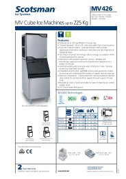
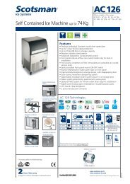
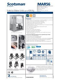
G. INSTALLATION PRACTICE<br />
9<br />
8<br />
1. Hand shut-off valve<br />
2. Water filter<br />
1<br />
3. Water supply line (flexible hose)<br />
4. 3/4" male fitting<br />
2 3<br />
5<br />
4<br />
7<br />
5. Vented drain<br />
6. Open trapped vented drain<br />
7. Drain fitting<br />
8. Main switch<br />
9. Power line<br />
6<br />
WARNING. This icemaker is not designed for outdoor installation and will not function in<br />
ambient temperatures below 10°C (50°F) or above 40°C (100°F).<br />
This icemaker will malfunction with water temperatures below 5°C (40°F) or above 35°C<br />
(90°F).
Page 12<br />
Page 12<br />
OPERATING INSTRUCTIONS<br />
START UP<br />
After having correctly installed the ice maker and<br />
completed the plumbing and electrical<br />
connections, perform the following “Start-up” procedure.<br />
A. Withdraw the condenser air filter then<br />
remove the unit front panel and locate the cleaning<br />
switch on the control box.<br />
B. Set the cleaning switch in the cleaning<br />
position. This will close the electrical circuit to the<br />
water inlet valve and to the hot gas valve<br />
C. Switch ON the power line disconnect switch<br />
and push the green button switch. Unit will start<br />
up in charging cycle mode. During this cycle the<br />
components energized are:<br />
WATER INLET SOLENOID VALVE<br />
HOT GAS SOLENOID VALVE<br />
The Water pump and the Fan motor in the air<br />
cooled versions, are also in operation.<br />
D. Let unit stay in charging cycle for about<br />
three/four minutes till water is coming out from<br />
the drain hose, then move the cleaning switch to<br />
the operation position.<br />
NOTE. During the charging cycle, the water<br />
inlet solenoid valve is energized. The water<br />
flows through the valve to the b<strong>ac</strong>k side of the<br />
evaporator platen and then down to fill up the<br />
icemaker sump for the next freezing cycle.<br />
OPERATIONAL CHECKS<br />
E. The unit now starts its first freezing cycle<br />
with the following components in operation:<br />
COMPRESSOR<br />
WATER PUMP<br />
FAN MOTOR in air cooled version<br />
F. Check to see through the ice discharge<br />
opening that the spray system is correctly seated<br />
and that the water jets uniformely re<strong>ac</strong>h the<br />
interior of the inverted cup molds; also make sure<br />
that the plastic curtain is hanging freely and there<br />
is not excessive water spilling through it.<br />
G. The ice making process takes pl<strong>ac</strong>e<br />
thereby, with the water sprayed into the molds<br />
that gets gradually refrigerated by the heat<br />
exchanged with the refrigerant flowing into the<br />
evaporator serpentine.<br />
H. When the evaporator temperature re<strong>ac</strong>hes<br />
a preset value the evaporator thermostat or cube<br />
size control changes its cont<strong>ac</strong>ts; the freezing<br />
cycle ends and starts the defrost or harvest<br />
cycle.<br />
Freezing time will range between 20 and 22<br />
minutes in a 21°C ambient temperature. Longer<br />
time for temperature above, shorter when below.<br />
Average complete cycle range is about 23 to 25<br />
minutes.<br />
I. Check, during the first defrost/harvest<br />
cycle, that the incoming water flows correctly<br />
into the sump in order to re-fill it and the surplus<br />
overflows through the overflow drain tube.<br />
J. Check the texture of ice cubes just<br />
released. Right size must have a small depression<br />
(about 5-6 mm) in their crown.<br />
If not, wait for the second defrost/harvest cycle<br />
before performing any adjustment.<br />
K. If required, the length of the freezing cycle<br />
can be modified by turning the knob of the cube<br />
size control or evaporator thermostat located in<br />
front of the control box until the desired size is<br />
<strong>ac</strong>hieved.<br />
If the ice cubes are shallow and cloudy, it is<br />
possible that the ice maker runs short of water<br />
during the end of the freezing cycle or, the quality<br />
of the supplied water requires the use of an<br />
appropriate water filter or conditioner.<br />
L. During the defrost or harvest cycle hold a<br />
handful of ice cubes against the bulb of the<br />
storage bin thermostat; the icemaker switch OFF<br />
in about one-two minutes.<br />
Take out the ice from the storage bin thermostat.<br />
The ice maker should restart automatically in<br />
three-four minutes.<br />
NOTE. The bin thermostat is f<strong>ac</strong>tory set at<br />
1°C (35°F) OUT and 4°C (39°F) IN.<br />
M. Re-fit the unit front panel then instruct the<br />
owner/user on the general operation of the ice<br />
m<strong>ac</strong>hine and about the cleaning and care it<br />
requires.
Page 13<br />
Page 13
Page 14<br />
Page 14
Page 15<br />
Page 15<br />
OPERATION - ELECTRICAL SEQUENCE<br />
The following charts illustrate which switches<br />
and components are ON or OFF during the two<br />
phases of the icemaking cycle.<br />
Refer to the wiring diagram for reference.<br />
FREEZING CYCLE<br />
Electrical components ON OFF<br />
Compressor............................................•<br />
Water Pump ...........................................•<br />
Fan Motor (Air cooled only) ....................•<br />
Hot Gas Valve ........................................ •<br />
Inlet Water Valve .................................... •<br />
Electrical Controls CLOSE OPEN<br />
Evaporator Thermostat (cont<strong>ac</strong>ts 3-4) ...•<br />
Evaporator Thermostat (cont<strong>ac</strong>ts 3-2) ... •<br />
Bin Thermostat .......................................•<br />
HARVEST CYCLE<br />
Electrical components ON OFF<br />
Compressor............................................•<br />
Water Pump ........................................... •<br />
Fan Motor (Air cooled only) .................... •<br />
Hot Gas Valve ........................................•<br />
Inlet Water Valve ....................................•<br />
Electrical Controls CLOSE OPEN<br />
Evaporator Thermostat (cont<strong>ac</strong>ts 3-4) ... •<br />
Evaporator Thermostat (cont<strong>ac</strong>ts 3-2) ...•<br />
Bin Thermostat .......................................•<br />
Freeze Cycle<br />
Average Discharge Pressure<br />
A/C:<br />
7 ÷ 11 bars (100÷155 psig)<br />
Average Discharge Pressure<br />
W/C:<br />
8.5 ÷ 10 bars (120÷140 psig)<br />
Suction Pressure<br />
End Freeze Cycle: 0 ÷ 0.1 bar (0 ÷ 1.5 psig)<br />
REFRIGERANT METERING DEVICE:<br />
capillary tube<br />
REFRIGERANT CHARGE (R 134 A)<br />
Model Air cooled Water cooled<br />
AC 46 260 gr ( 9.5 oz.) 250 gr (9.0 oz.)<br />
AC <strong>56</strong> 260 gr ( 9.5 oz.) 250 gr (9.0 oz.)<br />
AC 86 (50 Hz) 280 gr (10.0 oz.) 250 gr (9.0 oz.)<br />
AC 86 (60 Hz) 290 gr (10.3 oz.) 250 gr (9.0 oz.)<br />
COMPONENTS DESCRIPTION<br />
A. WATER PUMP<br />
The water pump operates continually throughout<br />
the freezing cycle.<br />
The pump primes the water from the sump to the<br />
spray system and through the spray nozzles<br />
sprays it into the inverted cup molds to be frozen<br />
into crystal clear ice cubes.<br />
B. WATER INLET SOLENOID VALVE -<br />
3/4 MALE FITTING<br />
The water inlet solenoid valve is energized only<br />
during the defrost cycle.<br />
When energized it allows a metered amount of<br />
incoming water to flow over the evaporator cavity<br />
to assist the hot gas in defrosting the ice cubes.<br />
The water running over the evaporator cavity<br />
drops by gravity, through the dribbler holes of the<br />
platen, into the sump.<br />
On water cooled versions the water inlet solenoid<br />
valve has one inlet and two outlets with two<br />
separate solenoids energized the first (ice<br />
productioon) by the cont<strong>ac</strong>ts 3-2 of the evaporator<br />
thermostat and the second (water cooled<br />
condenser) by a specific hi pressure control.<br />
C. HOT GAS SOLENOID VALVE<br />
The hot gas solenoid valve consists basically in<br />
two parts: the valve body and the valve coil.<br />
Located on the hot gas line, this valve is energized<br />
by the cont<strong>ac</strong>ts 3-2 of the evaporator thermostat<br />
during the defrost cycle.<br />
During the defrost cycle the hot gas valve coil is<br />
<strong>ac</strong>tivated so to attr<strong>ac</strong>t the hot gas valve piston in<br />
order to give way to the hot gas discharged from<br />
compressor to flow directly into the evaporator<br />
serpentine to defrost the formed ice cubes.<br />
D. BIN THERMOSTAT<br />
The bin thermostat control body is located in the<br />
front of control box behind the front louvered<br />
panel.<br />
The thermostat sensing tube is located into a<br />
bulb holder on the side wall of the ice storage bin<br />
where it automatically shuts the icemaker OFF<br />
when in cont<strong>ac</strong>t with the ice and re-starts the<br />
icemaker when the ice is removed. F<strong>ac</strong>tory<br />
settings are 1°C (35°F) OUT and 4°C (39°F) IN.<br />
E. CUBE SIZE CONTROL (EVAPORATOR<br />
THERMOSTAT)<br />
The cube size control (evaporator thermostat)<br />
body is located in the front of control box behind<br />
the front louvered panel; it’s basically a reverse<br />
<strong>ac</strong>ting temperature control which closes the<br />
cont<strong>ac</strong>ts 3-2 when its temperature decreases<br />
and closes the opposite cont<strong>ac</strong>ts 3-4 when the<br />
temperature rises.
Page 16<br />
Page 16<br />
The thermostat sensing bulb is located into a<br />
plastic tube (bulb holder) secured by two clips<br />
directly to the evaporator serpentine.<br />
This control determines the length of the freezing<br />
cycle and correspondingly the size of the cubes.<br />
A lower setting will produce a larger cube<br />
(oversize) while a higher setting a smaller <strong>cuber</strong><br />
(shallow size).<br />
When closed on cont<strong>ac</strong>ts 3-2 it <strong>ac</strong>tivates the<br />
defrost or harvest cycle components.<br />
The cube size control is set up in the f<strong>ac</strong>tory<br />
(knob in the bl<strong>ac</strong>k dot position) and doesn't<br />
require any adjustment when the ambient<br />
temperature remains between 15 and 30°C<br />
(60 and 90°F).<br />
F. FAN MOTOR (Air cooled version)<br />
The fan motor is electrically connected in parallel<br />
to the water pump and it operates continuously<br />
only during the freezing cycle keeping the proper<br />
head pressure by circulating air through the<br />
condenser fins.<br />
G. COMPRESSOR<br />
The hermetic compressor is the heart of the<br />
refrigerant system and it is used to circulate and<br />
retrieve the refrigerant throughout the entire<br />
system. It compresses the low pressure<br />
refrigerant vapor causing its temperature to rise<br />
and become high pressure hot vapor (hot gas)<br />
which is then released through the discharge<br />
valve.<br />
H. WATER SPRAY SYSTEM<br />
Through its nozzles it sprays the water in e<strong>ac</strong>h<br />
individual cup to be frozen into ice.<br />
I. CLEANING SWITCH<br />
Located on the bottom side of the control box is<br />
used to energize the water inlet and the hot gas<br />
valves so to charge the water into the sump of the<br />
m<strong>ac</strong>hine when neaded.<br />
J. HI PRESSURE CONTROL (Water cooled<br />
version)<br />
Used only on the water cooled versions it operates<br />
to keep between 8.5 and 10 bars (120 ÷ 140 psig)<br />
the hi-side or discharge pressure of the refrigerant<br />
system by energizing the coil of the water inlet<br />
solenoid valve that control the cooling water flow<br />
to the condenser.<br />
K. GREEN MASTER SWITCH PUSH<br />
BUTTON<br />
Located in the front of the m<strong>ac</strong>hine it’s used to<br />
switch ON and OFF the unit by pushing its green<br />
push button. When ON, its green light is ON as<br />
well.<br />
L. RED ALARM/RE-SET PUSH BUTTON<br />
Located in the front of the m<strong>ac</strong>hine (just beside<br />
the Master Switch) it works in conjuction with the<br />
Cleaning Remind Board and it’s <strong>ac</strong>tivated when:<br />
• Consensing temperature is higher then 70°C<br />
(air cooled version) - ON steady with m<strong>ac</strong>hine<br />
in OFF mode<br />
• Condensing temperature is higher then 60°C<br />
(water cooled version) - ON steady with<br />
m<strong>ac</strong>hine in OFF mode<br />
• Condenser sensor out of order - Blinking<br />
twice and repeat with m<strong>ac</strong>hine in OFF mode<br />
• Condenser air filter need to be cleaned - ON<br />
steady with m<strong>ac</strong>hine in ON mode<br />
• Water system need to be cleaned - Slow<br />
blinking with m<strong>ac</strong>hine in ON mode.<br />
On the first two cases it’s possible to Re-Set the<br />
operation of the m<strong>ac</strong>hine pushing and hold the<br />
Red Alarm Re-Set Button by 5" till the Red Light<br />
is OFF.<br />
On the third case, it’s necessary first to repl<strong>ac</strong>e<br />
the condenser sensor then, push and hold for 5"<br />
the Red Re-Set Button.<br />
M. CLEANING REMIND PC BOARD<br />
Located on the front left side of the m<strong>ac</strong>hine, it<br />
works in conjuction with the condenser sensor<br />
and the Red Alarm Re-Set Push Button.<br />
It consists of a Printed Circuit Board with a step<br />
down transformer (230V - 12V), a relay, a Dip<br />
Switch with two keys, a Jumper for the set up of<br />
the Cut OFF/Alarm condensing temperature<br />
(70°C - jumper OUT - for air cooled version and<br />
60°C - jumper IN - for water cooled version), a<br />
green four cont<strong>ac</strong>ts connector for power IN and<br />
OUT, a Red socket for the Water Level Sensor<br />
(future use on EC series only), a Bl<strong>ac</strong>k socket for<br />
the Condenser Sensor and a White socket for the<br />
Red Alarm Re-Set Push Button.<br />
The main function of this PC Board is to switch<br />
OFF the m<strong>ac</strong>hine when the condensing temperature<br />
is higher of its setting value or signal out<br />
the need for the cleaning of the condenser air<br />
filter (air cooled only) or of the water system.<br />
The time between the signal out for the cleaning<br />
of the water system can be modified <strong>ac</strong>cording to<br />
the setting of the two Dip Switches as below:<br />
TIME 1 2<br />
1 MONTH ON ON<br />
3 MONTHS OFF ON<br />
6 MONTHS ON OFF<br />
1 YEAR OFF OFF<br />
Once cleaned the water system, it’s necessary to<br />
cancel the time stored into the PC Board by
Page 17<br />
Page 17<br />
pushing and hold for more then 20" the Red<br />
Alarm Re-Set Button till it starts to blink.<br />
N. CONDENSER AIR FILTER<br />
(Air cooled version)<br />
Located in front of the air cooled condenser can<br />
be removed by withdrawing it through the opening<br />
of the front panel for cleaning or repl<strong>ac</strong>ing.<br />
A lower plastic guide, installed inside the unit, is<br />
used for the correct sliding and location of the air<br />
filter.<br />
O. CONDENSER SENSOR<br />
The condenser temperature sensor probe,<br />
located within the condenser fins (air cooled<br />
version) or in cont<strong>ac</strong>t with the tube coil (water<br />
cooled version) detects the condenser temperature<br />
variations and signals them by supplying<br />
current, at low voltage, to the P.C. BOARD.<br />
In case the condenser temperature rises and<br />
re<strong>ac</strong>hes 70°C (160°F) - on air cooled <strong>model</strong>s - or<br />
60°C (140°F) - on water cooled <strong>model</strong>s - the<br />
current arriving to the micro processor is such to<br />
cause an immediate and total stop of the m<strong>ac</strong>hine<br />
operation.
Page 18<br />
Page 18
Page 19<br />
Page 19<br />
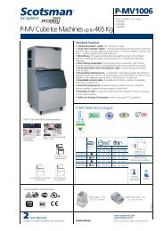
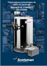
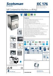
WIRING DIAGRAM<br />
AC 46 - AC <strong>56</strong> / AIR AND WATER COOLED 230/50-60/1<br />
The unit is shown on freezing cycle
Page 20<br />
Page 20<br />
WIRING DIAGRAM<br />
AC 86 / AIR AND WATER COOLED 230/50/1<br />
The unit is shown on freezing cycle<br />
4 2
4<br />
2<br />
Page 21<br />
Page 21<br />
WIRING DIAGRAM<br />
AC 86 / AIR AND WATER COOLED 230/60/1<br />
The unit is shown on freezing cycle
Page 23<br />
Page 23<br />
SERVICE DIAGNOSIS<br />
SYMPTON POSSIBLE CAUSE SUGGESTED CORRECTION<br />
Unit will not run Blown fuse Repl<strong>ac</strong>e fuse & check for cause of<br />
blown fuse.<br />
Main switch in OFF position<br />
Bin thermostat set improperly<br />
Loose electrical connections<br />
Turn switch to ON position<br />
Adjust rotating its setting screw<br />
Check wiring<br />
Red Alarm light ON Too Hi Condensing Temperature Reset the m<strong>ac</strong>hine (Push & hold<br />
the Reset Buttom for 5") and check<br />
for reason why<br />
Red Alarm light Blinking Twice Condenser sensor out of order Repl<strong>ac</strong>e it<br />
and repeat<br />
Compressor cycles intermittently Low voltage Check circuit for overloading<br />
Check voltage at the supply to the<br />
building. If low, cont<strong>ac</strong>t the power<br />
company<br />
Non-condensable gas in system<br />
Dirty condenser<br />
Air circulation blocked<br />
Compressor starting device with<br />
loose wires<br />
Purge the system<br />
Clean with v<strong>ac</strong>uun cleaner, air or<br />
stiff brush. (DO NOT use wire brush).<br />
Allow sufficient air sp<strong>ac</strong>e all<br />
around unit.<br />
Check for loose wires in starting<br />
device.<br />
Cubes too small Cube size control set improperly Check and adjust for proper<br />
operation.<br />
Capillary tube partially restricted<br />
Moisture in the system<br />
Shortage of water<br />
Shortage of refrigerant<br />
Blow charge, add new gas & drier,<br />
after ev<strong>ac</strong>uating system with<br />
v<strong>ac</strong>uum pump.<br />
Same as above.<br />
See remedies for shortage of water.<br />
Check for leaks & recharge.<br />
Cloudy cubes Shortage of water See remedies for shortage of water.<br />
Dirty water supply<br />
Accumulated impurities<br />
Use water softner or water filter.<br />
Use SCOTSMAN Ice M<strong>ac</strong>hine<br />
cleaner.<br />
Shortage of water Water spilling out through curtain Check or repl<strong>ac</strong>e curtain.<br />
Water solenoid valve not opening<br />
Water leak in sump area<br />
Water flow control plugged<br />
Repl<strong>ac</strong>e valve.<br />
Locate and repair.<br />
Remove and clean.
Page 24<br />
Page 24<br />
SERVICE DIAGNOSIS<br />
SYMPTON POSSIBLE CAUSE SUGGESTED CORRECTION<br />
Irregular cubes size & Some jets plugged Remove jet cover and clean.<br />
some cloudy<br />
Shortage of water<br />
See shortage of water.<br />
Unit not levelled<br />
Poor pumping<br />
Level as required.<br />
Check and/or repl<strong>ac</strong>e the water pump.<br />
Cubes too large Cube size control set improperly Check and adjust for proper operation.<br />
Decreased ice cap<strong>ac</strong>ity Inefficient compressor Repl<strong>ac</strong>e.<br />
Leaky water valve<br />
Non-condensable gas in system<br />
Poor air circulation or excessive<br />
hot location<br />
Overcharge of refrigerant<br />
Capillary tube partially restricted<br />
Undercharge of refrigerant<br />
Discharge head pressure too high<br />
Clogged air filter<br />
Repair or repl<strong>ac</strong>e.<br />
Purge the system.<br />
Relocate the unit or provide for<br />
more ventilation.<br />
Correct the charge. Purge off slowly.<br />
Blow charge, add new gas & drier,<br />
after ev<strong>ac</strong>uating system with<br />
v<strong>ac</strong>uum pump.<br />
Charge to data plate indication.<br />
See incorrect discharge pressure.<br />
Clean or repl<strong>ac</strong>e.<br />
Poor harvest Restriction in incoming water line Check water valve strainer and flow<br />
control. If necessary enlarge the<br />
flow control orifice.<br />
Too short defrost time<br />
Cube size control set for too large<br />
cubes<br />
Water inlet valve not opening<br />
Hot gas valve orifice restricted<br />
Air vented holes in mold cups plugged<br />
Discharge head pressure too low<br />
Check temperature control.<br />
Repl<strong>ac</strong>e if necessary.<br />
Re-set cube size control.<br />
Valve coil with open winding.<br />
Repl<strong>ac</strong>e valve.<br />
Repl<strong>ac</strong>e hot gas valve assy.<br />
Clean out holes.<br />
See incorrect discharge pressure<br />
Unit won't harvest Inoperative cube size control Repl<strong>ac</strong>e cube size control<br />
Hot gas valve not opening<br />
Water solenoid valve not opening<br />
Valve coil with open winding.<br />
Repl<strong>ac</strong>e valve.<br />
Valve coil with open winding.<br />
Repl<strong>ac</strong>e valve.<br />
Incorrect discharge pressure Dirty air filter Clean or repl<strong>ac</strong>e.<br />
Inoperative hi press control<br />
(Water cooled)<br />
Water inlet valve to condenser<br />
partially clogged<br />
Repl<strong>ac</strong>e.<br />
Clean or repl<strong>ac</strong>e.<br />
Excessive water in unit base Water tubing leaking Check. Tighten or repl<strong>ac</strong>e.
Page 25<br />
Page 25<br />
MAINTENANCE AND CLEANING INSTRUCTIONS<br />
A. GENERAL<br />
The periods and the procedures for maintenance<br />
and cleaning are given as guides and are not to<br />
be construed as absolute or invariable.<br />
Cleaning, especially, will vary depending upon<br />
local water and ambient conditions and the ice<br />
volume produced; and, e<strong>ac</strong>h icemaker must be<br />
maintened individually, in <strong>ac</strong>cordance with its<br />
particular location requirements.<br />
C. CLEAN - REPLACE OF AIR<br />
CONDENSER FILTER<br />
1. Withdraw the air filter from the front through<br />
the opening of the front panel.<br />
B. ICEMAKER<br />
The following maintenance should be scheduled<br />
at least two times per year on these icemakers.<br />
1. Check and clean the water line strainer.<br />
2. Check that the icemaker is levelled in side<br />
to side and in front to rear directions.<br />
3. Check for water leaks and tighten drain line<br />
connections. Pour water down bin drain line to be<br />
sure that drain line is open and clear.<br />
4. Check size, condition and texture of ice<br />
cubes. Perform adjustment of cube size control<br />
as required.<br />
5. Check the bin thermostat to test shut-off.<br />
Put a showelfull of ice cubes in cont<strong>ac</strong>t with the<br />
bin thermostat bulb for at least one minute.<br />
This should cause the ice maker to shut off.<br />
Within few seconds after the removal of the<br />
ahowelfull of ice from bin thermostat bulb, the<br />
icemaker restarts.<br />
NOTE. Within minutes after the ice is removed<br />
from the bulb holder tube, the sensing bulb<br />
inside the tube will warm up and cause the<br />
icemaker to restart. This control is f<strong>ac</strong>tory set<br />
and should not be reset until testing is<br />
performed.<br />
6. Check for refrigerant leaks.<br />
NOTE. The new AC 46 & AC <strong>56</strong> series, in the<br />
air cooled version, are standard equipped<br />
with an air condenser filter as well as a<br />
Cleaning Reminder Board to remind to the<br />
end user the need for the cleaning of the air<br />
filter or of the water system (Red Alarm Light<br />
ON Steady or Blinking rispectively with<br />
m<strong>ac</strong>hine in operation).<br />
2. Blow pressurised air on the opposite direction<br />
of the condenser air flow so to remove the<br />
dust <strong>ac</strong>cumulated.<br />
3. If pressurised air is not available, use tap<br />
water always in the counter flow air diretcion.<br />
Once cleaned shake it so to remove most of<br />
the <strong>ac</strong>cumulated water, then dry it using an<br />
hair dryer.<br />
NOTE. In case the air filter strainer is damaged<br />
repl<strong>ac</strong>e it with a new one.<br />
4. Install it again by pushing it through the front<br />
panel opening.<br />
D. CLEANING INSTRUCTIONS OF<br />
WATER SYSTEM<br />
1. Remove the front and top panels to gain<br />
<strong>ac</strong>cess either to the control box and to the<br />
evaporator.<br />
2. Make sure that all ice cubes have been<br />
released from their cups, then switch OFF the<br />
m<strong>ac</strong>hine at front master button switch.<br />
3. Scoop out all the ice cubes stored into the<br />
bin in order to prevent them from being<br />
contaminated with the cleaning solution.
Page 26<br />
Page 26<br />
4. Remove the plastic cup located on the bottom<br />
of sump/freezing chamber to drain out all water<br />
and scale deposits.<br />
7. Using a bottle, poor fresh water into the<br />
bottom of the sump/freezing chamber to clean<br />
out most of scale deposit.<br />
5. Unloose the two thumb scews and remove<br />
the curtain.<br />
8. Install again the spray platen, the curtain as<br />
well as the bottom plastic cup.<br />
9. Prepare the cleaning solution by diluting in<br />
a plastic container two liters of warm water (45°-<br />
50°C) with 0,2 liters of Ice M<strong>ac</strong>hine Cleaner.<br />
WARNING. The SCOTSMAN Ice M<strong>ac</strong>hine<br />
Cleaner contains Phosphoric and<br />
Hydroxy<strong>ac</strong>etic <strong>ac</strong>ids.<br />
These compounds are corrosive and may<br />
cause burns if swallowed, DO NOT induce<br />
vomiting. Give large amounts of water<br />
or milk. Call Physician immediately.<br />
In case of external cont<strong>ac</strong>t flush with<br />
water. KEEP OUT OF THE REACH OF<br />
CHILDREN.<br />
10. Remove the evaporator cover then slowly<br />
pour onto the evaporator platen the cleaning<br />
solution. With the help of a brush dissolve the<br />
most resistant and remote scale deposits in the<br />
platen.<br />
11. Switch ON again the m<strong>ac</strong>hine at front master<br />
button switch to start the icemaking process.<br />
Allow the ice maker to operate for about 20<br />
minutes. Then turn the cleaning switch to the<br />
"cleaning" position (II) till the release of the ice<br />
cubes from their cups.<br />
6. Lift up the entire spray platen from its bottom<br />
seat and take it out to clean it separately.<br />
NOTE. The amount of Cleaner and the time<br />
needed for the cleaning of water system<br />
depends of the water conditions.<br />
12. Switch OFF the ice maker at master button<br />
switch then flush out the cleaning solution from<br />
the sump reservoir by taking off the sump plastic<br />
cup. Once flushed out install again the sump<br />
plastic cup.<br />
13. Pour onto the evaporator cavity two or<br />
three liters of clean potable water to rinse the<br />
mold cups and the platen.<br />
14. Switch ON again the m<strong>ac</strong>hine. The water<br />
pump is again in operation to circulate the water<br />
in order to rinse the entire water system.
Page 27<br />
Page 27<br />
Do the operation as per steps 12 and 13 twice so<br />
to be sure no more tr<strong>ac</strong>es of descaling solution<br />
remains into the sump.<br />
15. With m<strong>ac</strong>hine in OFF mode pour on the<br />
upper side of the evaporator platen fresh water<br />
with a capfull of sanitizing solution then turn<br />
again the m<strong>ac</strong>hine in normal operating mode so<br />
to sanitize all the water system for approx. 10<br />
minutes.<br />
NOTE. Do not mix descaling with sanitizing<br />
solution to avoid the generation of a very<br />
aggressive <strong>ac</strong>id.<br />
16. Switch OFF the m<strong>ac</strong>hine and flush out the<br />
sanitizing solution from the sump reservoir then<br />
with the switch in "cleaning" position (II), switch it<br />
ON again.<br />
When water starts overflowing through the<br />
drain line, set the switch to "operation" (I)<br />
position. The unit is now ready to resume<br />
normal operation.<br />
17. Pl<strong>ac</strong>e again the evaporator cover and the<br />
unit service panels.<br />
18. At completion of the freezing and harvest<br />
cycle make sure of proper texture and clearness<br />
of the ice cubes and that, they do not have any<br />
<strong>ac</strong>id taste.<br />
ATTENTION. In case the ice cubes are<br />
cloudy-white and have an <strong>ac</strong>id taste, melt<br />
them immediately by pouring on them<br />
some warm water. This to prevent that<br />
somebody could use them.<br />
19. Wipe clean and rinse the inner surf<strong>ac</strong>es of<br />
the storage bin.<br />
REMEMBER. To prevent the <strong>ac</strong>cumulation<br />
of undesirable b<strong>ac</strong>teria it is necessary to<br />
sanitize every week the interior of the storage<br />
bin.