Ed. 07/2006 - Scotsman
Ed. 07/2006 - Scotsman
Ed. 07/2006 - Scotsman

You also want an ePaper? Increase the reach of your titles
YUMPU automatically turns print PDFs into web optimized ePapers that Google loves.
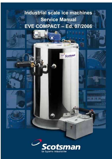
Service manual<br />
Industrial scale ice machines<br />
Service Manual<br />
EVE COMPACT – <strong>Ed</strong>. <strong>07</strong>/<strong>2006</strong><br />
0<br />
Rev. <strong>07</strong>/<strong>2006</strong>
Service Manual<br />
EVE Compact Units<br />
I. Safety advice page 2<br />
II. Introduction page 3<br />
III. A working outline page 4<br />
a) Water system page 5<br />
b) Ice outlet page 5<br />
c) Refrigeration system page 6<br />
i. Direct expansion with thermostatic valve<br />
ii. Direct expansion through flooding with level control<br />
Diagram of refrigerant circuit with main components page 7<br />
Diagram of refrigerant circuit (level control and screw comp.) page 8<br />
d) Inlet water page 9<br />
IV. Production diagram<br />
page10<br />
V. Technical characteristics page 11<br />
VI. Installation<br />
a) Handling, unpacking and disposal of packing page 18<br />
b) Positioning, levelling and access for maintenance page 19<br />
c) Water inlet connection page 19<br />
d) Ice outlet page 19<br />
e) Electrical connection page 20<br />
VII. START-UP and ADJUSTMENT<br />
First start-up and adjustment page 21<br />
Switch-off and Re-starting page 21<br />
Re-start procedure after supply interruption or Emergency stop page 21<br />
Salt addition page 22<br />
Salt feeding pump page 23<br />
Water/Brine tank page 24<br />
Scraping roller page 25<br />
Gear reducer protection page 26<br />
SET-UP and WORKING DATA – R22 page 27<br />
SET-UP and WORKING DATA – R404a/5<strong>07</strong> page 28<br />
VIII. CLEANING, MAINTENANCE and REPLACEMENT PROCEDURES page 29<br />
a. Replacement of gear reducer and motor page 30<br />
b. Water pump replacement page 30<br />
c. Replacement of Ice-breaker bush and scraper page 31<br />
d. Replacement of thermostatic valve/FTL page 32<br />
e. Replacement of deflector page 32<br />
f. Replacement of deflector and drip tray page 32<br />
g. Replacement of shaft bushes page 33<br />
IX. CLEANING and MAINTENANCE CONDENSING UNIT<br />
1. Condenser/oil cooler: cleaning and fan replacement page 34<br />
2. Compressor (see attached service manual) page 34<br />
3. Liquid receiver: safety pressure valve page 34<br />
4. Filters: oil suction and liquid line page 35<br />
5. Valves: solenoid, thermostatic, check, non return page 35<br />
6. Electric control panel: wiring diagram (reciprocating compressors) page 36<br />
Topographic electrical diagram (reciprocating compressor) page 37<br />
7. Electric control panel: wiring diagram (screw compressors) page 39<br />
Topographic electrical diagram (screw compressor) page 40<br />
X. FAULT ANALYSIS page 42<br />
XI. Exploded views and Part List page 44<br />
1 Rev. <strong>07</strong>/<strong>2006</strong>
Service manual<br />
I. Safety advices<br />
Thank you for purchasing a <strong>Scotsman</strong> EVE machine, we would like to draw your attention<br />
to important safety precautions to be used when operating the equipment.<br />
The refrigeration cycle operates by compression of vapour, with high and low pressure<br />
features and controlled refrigerant.<br />
The plant has to be operated in accordance with the attached use and maintenance<br />
instructions.<br />
Components such as pressure switches and safety valves should be checked periodically<br />
to ensure correct operation.<br />
Maintenance on the equipment should only be carried out by qualified personnel, technical<br />
support is always available.<br />
During design and construction of our equipment we evaluate the potential dangers, solve<br />
them where possible using normal safety practice and constructional standards but, some<br />
residual risks remain for example:<br />
• Contact with refrigerant can cause freezing (scalds)<br />
• Refrigerant leaks can cause suffocation in closed environments<br />
• High temperatures are present on high pressure circuits<br />
• Safety valves can vent refrigerant at high pressure and high<br />
temperature<br />
• The plant has been designed for maximum ambient temperature of<br />
+40°C<br />
On the serial number plate of the machine are indicated the pressure and<br />
temperature working limits (TS and PS).<br />
If a check valve is installed before the safety valve on the liquid receiver,<br />
ensure that is always in open position.<br />
The above is not an exhaustive list; risk assessments and evaluation of potential hazards<br />
should be carried out before any work is started.<br />
2<br />
Rev. <strong>07</strong>/<strong>2006</strong>
Service Manual<br />
II. INTRODUCTION<br />
Linea.Net Milano Srl manufacture flake ice machines in various production capacities and<br />
configurations to suit the numerous market demands.<br />
The agro-food industry (bread making, meat processing, cheese, etc.) and in particular the<br />
fishing industry, have found flake ice to offer many advantages over traditional ice cubes<br />
or crushed ice.<br />
In the chemical and cement industry flake ice is used during production to avoid premature<br />
drying out or temperature control.<br />
The following is an example of sectors that use ice:<br />
- On board installations – Fishing<br />
- Fishing industry - Processing<br />
- Manufacture of fish products<br />
- Fish markets<br />
- Distribution of fresh fish<br />
- Retailers of fish or fish products<br />
- Supermarkets<br />
- Delicatessens<br />
- Meat markets<br />
- Manufacture of poultry and game products<br />
- Production of salamis and sausages<br />
- Oven products and industrial bread-making<br />
- Production of dairy products and cheeses<br />
- Textile industry and paint production<br />
- Chemical-pharmaceutical companies<br />
- Building and construction companies (in compliance with European Standard EN206-<br />
1 : 2000)<br />
Our vast experience (since 1973) allows us to offer machines with a high level of reliability,<br />
vouched for by numerous clients who are satisfied with the machines they have used.<br />
These machines have been designed to work under stress and offer the following<br />
advantages:<br />
- Reliability- Long-life – Reduced running and maintenance costs<br />
Other than the advantage of reduced production costs when using ice, a “dry and subcooled<br />
ice” will last longer and therefore provide a longer thermal inertia. Being flat and<br />
free from sharp corners (unlike crushed ice) it will not damage the outside of the product<br />
with which it comes into contact which, on defrosting, will lead to a deterioration of the<br />
merchandise.<br />
Example of model designation<br />
EVE200 AS = Fresh water version – Land Based – Air cooled condenser<br />
EVE200 LWS = Fresh water version – Land Based – Water cooled condenser<br />
EVE200 WS = Fresh water version – On Board – Sea water cooled condenser<br />
EVE200 AS SW = Sea water version - Land Based – Air cooled condenser<br />
EVE200 LW SW = Sea water version - Land Based – Sea water cooled condenser<br />
EVE201 WS SW = Sea water version – On Board – Sea water cooled condenser<br />
3 Rev. <strong>07</strong>/<strong>2006</strong>
Service manual<br />
III.<br />
A working outline<br />
A fixed vertical evaporator (1) is cooled by the refrigerant fluid evaporating on the inside.<br />
Water is evenly distributed from<br />
above onto the internal surface (2), 2<br />
4<br />
where it freezes once it comes into<br />
1<br />
contact with the cold wall. A<br />
helicoidal ice-breaker (3) is<br />
positioned parallel to the cylinder<br />
axis, almost in contact with the<br />
internal surface and the gear<br />
reducer (4) causes the central shaft<br />
(5) to turn at a constant speed. The<br />
ice-breaker is connected to the<br />
3<br />
central shaft with a satellite<br />
mechanism.<br />
The ice-breaker rotates on the<br />
5<br />
surface of ice; it removes it by<br />
8<br />
breaking it into flakes which then<br />
fall by gravity. A flat, vertical blade<br />
(6) follows the ice-breaker cleaning<br />
the surface of possible residue.<br />
Un-frozen water is returned to the<br />
reservoir (7).<br />
6<br />
Water pump (8) circulates water<br />
around the system.<br />
7<br />
4<br />
Rev. <strong>07</strong>/<strong>2006</strong>
Service Manual<br />
a. WATER SYSTEM<br />
At the base of the machine is the water reservoir in<br />
which the stainless steel pump is immersed. Water is<br />
pumped to the distributor from which it falls by gravity;<br />
there is a filter (2) and shut-off valve (1) on the toroidal<br />
distributor which is positioned internally and integral<br />
with the central shaft.<br />
Depending upon the application, there are two different<br />
types of distributor:<br />
a) Peralluman pipe with regular perforations and<br />
supply from above (land version)<br />
b) Stainless steel ring pipe with regular perforations and supply from the axis of the<br />
gear reducer (on board version)<br />
1<br />
3<br />
4<br />
2<br />
In the LAND version, a level sensor (3) allows a check to be carried out on the water flow.<br />
The upper part of the cylinder is rounded at the end in order to channel the water towards<br />
the walls of the cylinder.<br />
In the reservoir there is a float valve which regulates the flow of water from the external<br />
feed circuit in such a way that the level remains constant. The ice has to be dry and subcooled,<br />
for this the surface of the evaporator cylinder which is immediately in front of the<br />
scraper roller is not irrigated by the water distribution apparatus.<br />
b. ICE OUTLET<br />
The stainless steel shaft, positioned in the centre of the cylinder, is turned on its vertical<br />
axis by a gear reducer. Connected onto the shaft are two ‘V’ arms onto which the icebreaker<br />
is fixed on one side and the scraping roller on the other. This collects and cleans<br />
the surface of ice. The ice-breaker, turning on its<br />
own axis and rotating over the ice formed on the<br />
inside, detaches it by breaking it (see photo).<br />
5 Rev. <strong>07</strong>/<strong>2006</strong>
Service manual<br />
A deflector prevents the ice from falling into the water reservoir.<br />
Depending on the type of application and position of the machine, there must be adequate<br />
conveyors, containers or storage bins to collect the ice.<br />
The rotation speed determines the thickness of the ice: a slower speed corresponds to an<br />
increased thickness and sub-cooling of the ice.<br />
It is possible to alter the speed by applying a frequency converter (inverter) onto the<br />
electrical supply of the gear reducer.<br />
c. REFRIGERATION SYSTEM<br />
The evaporator cylinder is the main element in the machine. In its<br />
internal chambers the cold refrigerant circulates and absorbs<br />
heat. The walls facing the outside are insulated with foamed<br />
polyurethane. At the base of the cylinder there is a system for the<br />
removal of oil should the machine need to be closed down for<br />
long periods or for use during maintenance visits.<br />
DIRECT EXPANSION WITH THERMOSTATIC VALVE<br />
The refrigerant liquid is circulated through a coil on the inside of<br />
the cylinder (acting as heat exchanger), then with the use of a<br />
thermostatic valve is injected into the evaporator where it absorbs<br />
heat and evaporates. The vapour is recovered using the suction<br />
pipe as indicated in the technical diagrams.<br />
i. DIRECT EXPANSION through<br />
FLOODING with LEVEL CONTROL<br />
The refrigerant liquid flows through the<br />
pipe for sub-cooling with the use of a<br />
solenoid valve and a regulating valve (for<br />
the fall in pressure). It then floods the<br />
evaporator’s internal chambers, where the<br />
expansion phase takes place. If the<br />
machine is not completely flooded, the<br />
level control is carried out with an<br />
electronic controller (FTL) which controls<br />
the solenoid valve. The variation in<br />
pressure between the liquid and suction<br />
must have an ∆P no lower than 12 bar<br />
to guarantee an adequate supply of<br />
refrigerant.<br />
6<br />
Rev. <strong>07</strong>/<strong>2006</strong>
Service Manual<br />
Diagram of the refrigerant circuit with main components<br />
Pos. component Pos. component<br />
1 Evaporator/ice machine 30 rotalock tap<br />
3 F1 = mechanical cartridge filter 31 liquid receiver<br />
4 Vibration eliminator 32 Safety valve<br />
5 reciprocating compressor 33 globe tap<br />
6 high pressure switch 34 Solid cartridge filter<br />
7 low pressure switch 37 Solenoid valve<br />
8 Oil pressure switch 38 Liquid gauge<br />
9 Vibration eliminator 39 Thermostatic Valve<br />
10 oil separator 40 high pressure flexible pipe<br />
25 Non return valve 41 wheel tap<br />
27 Air cooled condenser 45 Lead sealed tap (open)<br />
28 pressure switch<br />
7 Rev. <strong>07</strong>/<strong>2006</strong>
Service manual<br />
Diagram of the refrigerant circuit with main components (level<br />
control and screw compressor version)<br />
Pos. component Pos. component<br />
1 Evaporator/ice machine 22 Liquid gauge<br />
2 FTL level control 24-41 wheel tap<br />
3 Mechanical cartridge filter 25 Non return valve<br />
5 screw compressor 26-33 globe tap<br />
6 high pressure switch 27 Air cooled condenser<br />
7 low pressure switch 28 pressure switch<br />
9 Vibration eliminator 31 liquid receiver<br />
10 oil separator 32 Safety valve<br />
11 Oil thermostat 34 Solid cartridge filter<br />
12 oil resistance 35 plate exchanger<br />
13 oil level indicator 36 dampness indicator<br />
14-15<br />
23-30<br />
rotalock tap 40 high pressure flexible pipe<br />
16 Oil cooler 42 mechanical filter<br />
17-21<br />
37-43<br />
solenoid valve 44 Thermostatic Valve<br />
18-38 Globe valve 45 Lead sealed tap (open)<br />
19 mechanical cartridge filter 46 mechanical filter<br />
20 Flow meter<br />
8<br />
Rev. <strong>07</strong>/<strong>2006</strong>
Service Manual<br />
d. INLET WATER<br />
The structural differences between sea and fresh water versions are minimal:<br />
1) Scraping blade is in plexiglass (more rigid) instead of rubber.<br />
2) Surface of the evaporator in contact with the water has a horizontally grooved<br />
surface to improve the thermal exchange.<br />
When using fresh water, the ice will vary depending on the hardness of the water, i.e.:<br />
a. Almost pure water such as rain water produces ice which is partly<br />
transparent and firmly attached to the cylinder wall<br />
b. Water with a high lime content causes a calcareous sediment to collect on<br />
the cylinder that also causes the ice to stick<br />
In both cases, the scraping roller breaks the layer of ice which forms on the wall of the<br />
cylinder, but a loss in quality may be experienced.<br />
Our experience has demonstrated that the addition of a small amount of salt (sodium<br />
chloride), eliminates these problems; the ice is compact and it breaks up into larger pieces.<br />
The amount of salt used however so low that it is not possible to taste it in the ice and it<br />
will not affect food products.<br />
The salt can be dosed with automatic measuring devices, or by a system that<br />
automatically regulates the conductivity of the water (average 1500 uS at +17°C).<br />
When using sea water, after checking that the machine is suitable for this type of use, it<br />
will be necessary to select a lower evaporating temperature than that used for fresh water,<br />
in order to obtain a good quality flake (normally between 4 and 8°C lower). The salinity of<br />
the water used is very important for the correct operation of the machine and often an<br />
adjustment made whilst in the harbour will provide different results when out to sea, due to<br />
different levels of salinity.<br />
Construction<br />
Differences<br />
FRESH<br />
WATER<br />
LAND<br />
FRESH<br />
WATER<br />
ON-BOARD<br />
AISI304<br />
smooth<br />
SEA<br />
WATER<br />
LAND<br />
SEA<br />
WATER<br />
ON-BOARD<br />
Evaporator internal<br />
surface<br />
AISI304 smooth<br />
AISI304 rifled AISI304 rifled<br />
Scraper material Rubber Rubber plexiglass plexiglass<br />
Water distributor<br />
Open, made of Closed ring, in Open, made of Closed ring, in<br />
aluminium AISI304 aluminium AISI304<br />
Water sensor level provided Not provided provided Not provided<br />
Through shaft<br />
Through shaft<br />
Supply for water By gravity, from<br />
By gravity, from<br />
and rotating<br />
and rotating<br />
distributor upper cover<br />
upper cover<br />
coupling<br />
coupling<br />
Refrigeration Power 100% 100% 115% 115%<br />
Evaporating<br />
Temperature<br />
-28°C -28°C -35°C -35%<br />
9 Rev. <strong>07</strong>/<strong>2006</strong>
Service manual<br />
IV. Production Diagram<br />
Diagramma Produzione / Production Diagram<br />
24.000<br />
22.000<br />
200 300 400<br />
650 800 1000<br />
1300 1500 2400<br />
20.000<br />
18.000<br />
16.000<br />
14.000<br />
Kg/24h<br />
12.000<br />
10.000<br />
8.000<br />
6.000<br />
4.000<br />
2.000<br />
0<br />
10 15 21 25 30 35<br />
T.alim.acqua °C/ Water temp.°C<br />
Models<br />
Ice production<br />
Kg/24h<br />
Thick. 1.8-2.2mm<br />
Water temp. 22°C,<br />
amb.temp. 35°C<br />
Ice production<br />
Kg/24h<br />
Max production<br />
Water temp. 15°C,<br />
amb.temp. 25°C<br />
Evaporating<br />
Temperature<br />
fresh water<br />
°C<br />
Evaporating<br />
Temperature<br />
sea water °C<br />
EVE200AS 1.600 1.750 -28 -35<br />
EVE300AS 2.300 2.550 -28 -35<br />
EVE400AS 3.500 3.700 -28 -35<br />
EVE650AS 5.800 6.200 -28 -35<br />
EVE800AS 7.500 7.870 -28 -35<br />
EVE1000AS 9.000 9.800 -28 -35<br />
EVE1300AS 11.000 12.000 -28 -35<br />
EVE1500AS 13.500 14.500 -28 -35<br />
EVE2400AS 21.000 22.060 -28 -35<br />
10<br />
Rev. <strong>07</strong>/<strong>2006</strong>
Service Manual<br />
V. TECHNICAL CHARACTERISTICS<br />
The machine is intended to be used at room temperature.<br />
Do not install in refrigerated rooms or in places where the temperature is too low.<br />
If this is unavoidable, provision must be made to protect the electrical parts from possible<br />
dampness and to ensure that the water in the reservoir does not freeze.<br />
The guarantee is no longer valid when there are signs that the machine has been used in<br />
conditions/environments outside the following:<br />
Conditions of use:<br />
Minimum<br />
Maximum<br />
Room temperature 2°C (36°F) 40°C (104°F)<br />
Temperature of inlet water (Fresh). 5°C ( 41°F) # 35°C (95°F)*<br />
Temperature of inlet water (Sea) 2°C (36°F) # 35°C (95°F)*<br />
Electrical voltage -10% +10%<br />
Water pressure 1 bar / 14 psi 5 bar / 70 psi<br />
# for lower temperatures it is advised to use a pre-heating system.<br />
* to obtain a good quality ice it will be necessary to reduce the water temperature to<br />
less than 25°C.<br />
11 Rev. <strong>07</strong>/<strong>2006</strong>
Service manual<br />
EVE200AS<br />
EVE300AS<br />
12<br />
Rev. <strong>07</strong>/<strong>2006</strong>
Service Manual<br />
EVE400AS<br />
EVE650AS<br />
13 Rev. <strong>07</strong>/<strong>2006</strong>
Service manual<br />
EVE800AS<br />
EVE1000AS<br />
14<br />
Rev. <strong>07</strong>/<strong>2006</strong>
Service Manual<br />
EVE1300AS<br />
EVE1500AS<br />
15 Rev. <strong>07</strong>/<strong>2006</strong>
Service manual<br />
EVE2400ASR<br />
Model<br />
W<br />
mm.<br />
D<br />
mm.<br />
H<br />
mm.<br />
Net<br />
Weight<br />
Kg<br />
Ice<br />
Outlet<br />
mm.<br />
A<br />
mm.<br />
B<br />
mm.<br />
Inlet<br />
water<br />
Inches<br />
Overflo<br />
w<br />
mm<br />
Packing<br />
Dimensions<br />
WxDxH<br />
Air freight packing<br />
dimensions<br />
WxDxH<br />
EVE200AS 1900 1650 1160 780 420 750 435 1/2 10 2150x1900x1360 -<br />
EVE300AS 1900 1650 1330 800 420 750 435 1/2 10 2150x1900x1530 -<br />
EVE400AS 1900 1650 1550 1150 420 750 435 1/2 10 2150x1900x1750 -<br />
EVE650AS 2600 2000 1610 2000 670 1035 545 1/2 10 2850x2250x1810 -<br />
EVE800AS 3200 1740 1820 2200 670 990 535 1/2 10 3450x1990x2020 -<br />
4400x2250x2300<br />
EVE1000AS 4100 2060 2210 2950 840 1265 545 3/4 10 4350x2310x2410<br />
+2750x700x580<br />
4900x2250x2300<br />
EVE1300AS 4600 2060 2200 3750 840 1135 545 3/4 10 4850x2310x2400<br />
+2750x700x580<br />
4850x23140x269 4900x2250x2300<br />
EVE1500AS 4600 2060 2495 4300 840 1135 545 3/4 10<br />
5<br />
+2750x700x580<br />
EVE2400AS<br />
6500<br />
1990<br />
2150<br />
1680<br />
2000<br />
2505<br />
5050<br />
2400<br />
1030 3/4 10<br />
6800x2340x2200<br />
2250x2100x2200<br />
-<br />
16<br />
Rev. <strong>07</strong>/<strong>2006</strong>
Service Manual<br />
REMOTE CONDENSING UNIT model UC-ASR<br />
Model<br />
W D H<br />
Electrical<br />
Consumption<br />
KW<br />
Nominal<br />
Current<br />
A<br />
Liquid<br />
line<br />
Ø mm.<br />
Suction<br />
line Ø<br />
mm.<br />
Net<br />
Weight<br />
Packing<br />
dimensions<br />
mm. mm. mm. Kg LxPxH mm.<br />
UC-200ASR 1390 870 1290 8,50 17,80 12 35 310 1500x1000x1450<br />
UC-300ASR 1775 870 1290 11,40 24,70 12 42 430 1900x1000x1450<br />
UC-400ASR 2025 1<strong>07</strong>0 1465 14,40 32,60 16 54 510 2200x1200x1600<br />
Specification and/or dimensions may change without prior notification.<br />
17 Rev. <strong>07</strong>/<strong>2006</strong>
Service manual<br />
VI.<br />
INSTALLATION<br />
a) Handling, unpacking and disposal of packing<br />
Check that the packaging has not been<br />
damaged during transportation.<br />
Proceed carefully with the unpacking, and<br />
then place the machine in its final position.<br />
To lift the equipment, secure the machine<br />
equally on all sides and lift using the rings<br />
which are fixed on the upper cover<br />
(EVE200 –EVE400) or the basement holes<br />
(EVE650-800). Avoid passing under the<br />
machine when lifted.<br />
It is possible to move the machine with a fork-lift lifting from the base (pay attention<br />
to the centre of gravity and the weight of the machine).<br />
All damage caused to the<br />
machine during<br />
transportation should be<br />
reported immediately to the<br />
deliverer and noted on the<br />
delivery slip.<br />
The crate is made of a<br />
recyclable material (wooden<br />
cage + polyethylene film);<br />
dispose of it via an<br />
ecological waste disposal<br />
company dealing in the<br />
recovery of prime materials<br />
and waste disposal.<br />
18<br />
Rev. <strong>07</strong>/<strong>2006</strong>
Service Manual<br />
a) Positioning, levelling and access for maintenance<br />
The equipment is factory assembled and ready to be connected to power and<br />
water.<br />
Position the equipment and ensure it is level (front to back and left to right).<br />
Remember to leave adequate space between walls etc. and other equipment, for<br />
maintenance and to ensure adequate air circulation.<br />
The ice outlet must be accessible for maintenance/repair procedures<br />
Ensure that the air cannot re-circulate from the ice outlet.<br />
b) Water inlet connection<br />
The water used for the formation of ice, must be connected to the reservoir, an<br />
overflow pipe must also be connected.<br />
If the temperature of the water is close to 0°C, it is advisable to pre-heat to avoid<br />
the formation of ice in the pipes and inside the reservoir.<br />
If the water is not completely pure, we advise applying a filter system for the<br />
purification.<br />
DIAGRAM with WATER INLET FILTER<br />
R= regulating tap for<br />
distributor water<br />
F3= mechanical filter<br />
P = pump<br />
F = ballvalve<br />
V = water reservoir<br />
S =water outlet<br />
F1 = cartridge filters<br />
F2 = pre-filter<br />
c) Ice outlet<br />
The discharge of the ice takes place at the base of the evaporator; dimensions of<br />
the outlet are indicated in the technical tables.<br />
It is possible to aim the outlet of ice with a stainless steel conveyor, made to<br />
measure, depending on the specific requirements.<br />
19 Rev. <strong>07</strong>/<strong>2006</strong>
Service manual<br />
When the machine is positioned on a storage bin, it is possible to control the filling<br />
with the use of mechanical or optical sensors or a timer that allows the machine to<br />
be stopped and started on demand.<br />
For safety reasons an ice level sensing device must be used on the outlet of<br />
the evaporator cylinder to avoid ice entering the machine and damaging the<br />
shaft and other rotating elements.<br />
1) Electrical connection<br />
The electrical connection should be carried out by specialised and qualified<br />
personnel. Installation must conform to all local standards of the country in<br />
question.<br />
The machine is provided with a main power isolator to cut-off the electrical supply.<br />
!<br />
Safety first!<br />
For a correct and secure installation use the right tools and<br />
protection.<br />
For the electrical connections please proceed as follows:<br />
• Drill the electrical board bottom part<br />
• Pass through the cables on the previous hole done applying a gasket to<br />
tighten<br />
• Connect cables to the terminal board<br />
20<br />
Rev. <strong>07</strong>/<strong>2006</strong>
Service Manual<br />
VII. START-UP and ADJUSTMENT<br />
First start-up and adjustment<br />
Once water and electrical connections have been completed, the ice machine can be<br />
switched-on. In case of malfunction the electrical controls will protect the machine from<br />
damage and the corresponding alarm light(s) will be illuminated.<br />
IN COLD ENVIRONMENTS ENSURE EQUIPMENT IS NOT STARTED UNTILL CRANK-<br />
CASE HEATER HAS WARMED THE OIL SUFFICIENTLY<br />
Check that the working suction pressure is as shown in the technical specifications.<br />
In all systems it is necessary to top up the lubricating oil, due to the combination of<br />
oil/refrigerant in the circuit. A few hours after the start-up of the system, it is advised, as a<br />
precaution, to check that the level of oil compressor is normal.<br />
At start-up, check the rotating direction of the shaft (anti-clockwise).<br />
In case of wrong rotation reverse two of the electrical supply phases.<br />
Open the water supply valves.<br />
The machine initially may produce low quality ice and should be adjusted as required.<br />
One hour after start-up check the following parameters:<br />
• Working pressures (high and low)<br />
• Water freezing level inside evaporator surface (if not completely frozen adjust the<br />
expansion valve)<br />
• Quality and ice thickness<br />
• Base deflector and ice scraper are clear of any ice build up<br />
SWITCH OFF and RE-STARTING<br />
When the machine is switched off using the STOP button provided in the electrical<br />
board.<br />
The liquid line solenoid valve will close and the equipment will enter a PUMP DOWN<br />
phase. At the end of this phase the rotating shaft and the water pump continues to<br />
operate to clear any ice residue from the evaporator surface (a timer defines when the<br />
drive-motor and the pump will stop).<br />
The machine will stop at the end of the pre-set time and is then ready to re-start.<br />
To start push the START button.<br />
Only in cases of emergency use the red button EMERGENCY-STOP<br />
RE-START PROCEDURE AFTER SUPPLY INTERUPTION or EMERGENCY STOP<br />
In the event of the machine experiencing an unexpected loss of power, the machine<br />
stopping because the gear reducer is blocked with ice or it was stopped unexpectedly for<br />
safety reasons; the evaporator will be flooded with refrigerant.<br />
On the re-start of the refrigerant system the presence of liquid in the suction line can<br />
seriously damage the compressor (especially with the ammonia models).<br />
To avoid this problem, we suggest you proceed as follows:<br />
- Check that the ice-breaker is free from ice (possibly by rinsing with water)<br />
- Empty the refrigerant out of the cylinder using a Pump-down procedure, having<br />
firstly partially closed the suction valve.<br />
Re-start the machine in normal working mode with all valves returned to their<br />
normal position.<br />
-<br />
21 Rev. <strong>07</strong>/<strong>2006</strong>
Service manual<br />
If the system initially produces low quality ice, it will be necessary to make some<br />
adjustments.<br />
a. completely open the downstream tap on the recirculation pump; close the tap slowly,<br />
until there is a constant level of water in the distribution channel without spillage and<br />
excessive return of water into the reservoir (LAND version) and the vertical distributor<br />
sprays the cylinder surface from all holes<br />
b. Salt addition – fresh water:<br />
Low salt dosing: ice is very dry and breaks in to small pieces; the machine becomes<br />
noisy and the ice breaks before the scraper arrives at the<br />
right position.<br />
Mechanical stress<br />
increases on the<br />
shaft with potential<br />
intervention of gearmotor<br />
overload<br />
protection device,<br />
and possible<br />
damage to the<br />
bushes.<br />
High salt dosing: ice is very soft and not really sub-cooled; there are areas where the ice<br />
did not detach; blocking the shaft.<br />
To rectify the problem it is suggested that salt is<br />
22<br />
Rev. <strong>07</strong>/<strong>2006</strong>
Service Manual<br />
added manually or with pump system.<br />
Automatic salt feeder pump: MPS<br />
03 <strong>07</strong> PRED (IP65)<br />
Electrical supply 230V/50-<br />
60/1 (198-242 VAC) – Do<br />
not install directly on<br />
inductive load – provide<br />
electrical contactor. The<br />
pump should be protected<br />
by a fuse 230VAC/630mA<br />
16W.<br />
The water supply pipe sends<br />
the brine (solution of water<br />
and Sodium Chloride-NaCl)<br />
directly into the water<br />
reservoir through the<br />
injection valve.<br />
Suction pipe should be<br />
placed in the brine tank<br />
together with the level control<br />
probe and the water drain.<br />
Between water tank base<br />
and salt feeder pump the<br />
difference in level should not<br />
be more than 150 cm.<br />
Operation/connections:<br />
connect transparent suction<br />
pipe to suction link (bottom<br />
valve on pump body) taking<br />
care to connect the pipe<br />
before the metal ring and pipe-stop; then connect the<br />
cone to the end. Check the valve O-ring and tighten the<br />
metal ring by hand. Place the suction filter on the water<br />
tank bottom. Suction pipe has to be short and straight to<br />
avoid bending that can prevent the pump working<br />
correctly.<br />
The pump body has a manual venting valve. To prime the<br />
pump proceed as follows:<br />
Place one side of the transparent pipe onto the valve pipe<br />
connector and the other side into the brine tank. Turn the<br />
handle on the pump body anticlockwise to open the valve.<br />
Start the pump and turn the flow to 50%, the air in the<br />
pump body will be pushed by the membrane out through<br />
the valve. Once the air is removed and the brine flows<br />
from the valve, close the valve.<br />
23<br />
Rev. <strong>07</strong>/<strong>2006</strong>
Service manual<br />
To help with the priming if the brine solution is very concentrated, remove the air from the<br />
valve pipe with a 20 cc syringe after having started the pump and opened the valve.<br />
The feeder pump is provided with a level alarm. When the brine falls below the minimum<br />
level, a red LED will light and the pump will stop.<br />
The dosage is constant, with the possibility of modifying the flow rate from zero to 100%.<br />
The front panel handle allows modification of the electronic system. It is advisable not to<br />
adjust the pump flow from 0 to 10% because this may cause an irregular flow rate.<br />
The bottom part of the filter should be cleaned once a year but if there are crystals<br />
present, it is suggested that cleaning should be carried out more frequently.<br />
WATER/BRINE TANK<br />
To avoid saturation of brine do not add more than 30% of salt by weight.<br />
As adjustment of the pump regulates the brine flow rate it is possible to meet the majority<br />
of customers’ requirements in respect of ice hardness and temperature.<br />
b2. manual dispenser pipe in Plexiglas: compressed salt tablets should be inserted<br />
and the hole at the bottom of the pipe should be gradually enlarged<br />
until the correct dosage is reached, this depends on the water hardness.<br />
NOTE: When the machine is stopped for a long period, the Plexiglas pipe<br />
should be removed to avoid re-starting with increased concentration of salt.<br />
This may lead to a formation of ice that is too soft and could block the<br />
ice-breaker.<br />
b3. manual dispenser drawer with double basin: add salt to the external basin;<br />
regulate the flow of water until the desired condition is achieved.<br />
With sea water machines it is not necessary to use these methods.<br />
If a variation in the quality of the ice (temperature) is required, it is not necessary to make<br />
alterations to the refrigerant system, it is enough to close the last holes in the distributor<br />
(closest to the ice-breaker) thereby obtaining a greater sub-cooling surface.<br />
However, on all machines, the opening of the thermostatic valve or damper can be<br />
regulated to alter the expansion temperature for a greater or lower sub-cooling of the ice.<br />
If the ice production is too low, proceed as follows:<br />
- from the inspection window check the frosting on the evaporator surface if this is not<br />
complete, open the thermostatic valve to increase the quantity of refrigerant<br />
- re-check the level of frosting, proceeding as above until maximum production is<br />
reached.<br />
- if necessary add more refrigerant (sight glass with presence of bubbles)<br />
If you wish to use the ice machine to obtain a daily amount which is lower than its capacity,<br />
it is advisable not to alter the refrigerant system but to stop the machine when the required<br />
amount of ice has been produced (timer or manual operation by the operator).<br />
Only in cases when the reduction has to be referred to the hourly production is it advisable<br />
to make alterations to the refrigerant circuit, reducing the refrigerant power of the<br />
compressor (partialisation or variation of a number of turns) and at the same time reducing<br />
24<br />
Rev. <strong>07</strong>/<strong>2006</strong>
Service Manual<br />
the quantity of water which flows over the evaporator surface (it is sufficient to close some<br />
holes of the water distribution channel).<br />
The stopping of the production can be done at any time without experiencing problems,<br />
providing the time is less than 10-15 minutes. If however, the machine needs to be<br />
stopped for over an hour, it is necessary to empty the gas contained in the evaporator<br />
cylinder by using the pump-down facility.<br />
A problem may occur when the machine is off for a long period and the temperature of the<br />
room where the machine is installed drops below 0°C. In such a case, it will be necessary<br />
to empty the water reservoir and all associated piping from the water supply, alternatively<br />
heat the area where the machine is installed.<br />
N.B. After 48 hours of working, it is advised that you substitute/clean the suction<br />
line filter in order to remove any oxidisation from brazing/welding or impurities that<br />
were present in the systems components.<br />
Water quality varies from area to area.<br />
It is recommended that a chemical analysis is carried out to ensure that correct<br />
cleaning/filtering/feeding systems are installed to prolong equipment life.<br />
SALT DOSAGE gr. NaCl in 24h (t.water +15°C)<br />
Model MIN. MAX.<br />
EVE 200/201 90 210<br />
EVE 300/301 130 320<br />
EVE 400/401 200 430<br />
EVE 650/651 300 700<br />
EVE 800/801 400 850<br />
EVE 1000/1001<br />
EVE 1300/1301<br />
EVE 1500/1501<br />
EVE 2400/2401<br />
500 1.100<br />
600 1.400<br />
800 1.700<br />
1.200 2.600<br />
SCRAPING ROLLER<br />
It is advisable to check that the position of the scraping roller corresponds to the original<br />
position during assembly. Its distance from the wall of the cylinder must be 0,4 mm, at<br />
room temperature of approximately 20°C.<br />
The roller must never touch the surface of the evaporator, contact will damage the<br />
surface.<br />
The adjustment of this distance is achieved by loosening the bolts that keep the box<br />
supports fixed, (positioned on the upper and lower part of the roller holder arm) and by<br />
moving the roller until it reaches the required distance. After carrying out the adjustment,<br />
ensure that the roller does not move whilst retightening the fixings.<br />
25 Rev. <strong>07</strong>/<strong>2006</strong>
Service manual<br />
GEAR REDUCER PROTECTION – RM4JA32<br />
- Gear reducer of the rotating shaft<br />
Electrical supply: 400/50/3<br />
!<br />
the measuring relay (over current protection) is supplied with<br />
the machine, to protect the gear reducer and shaft.<br />
The control relay (control RM4JA32) measures the current on the power supply to<br />
the motor and controls its operation (see electrical circuit diagram).<br />
1<br />
2<br />
3<br />
4<br />
Dim. 45x78 mm<br />
In order to avoid an excessive formation of ice<br />
before the restart, the measuring relay has to close down the water inlet and<br />
refrigerant inlet.<br />
The current relay (gear-motor protection), has to be installed as follows:<br />
A1-A2 electrical supply 24~240V<br />
C+B1 supply phase drive-motor (EVE201-301-401-651-801)<br />
C+B2 supply phase drive-motor (EVE1001-1301-1501-2401)<br />
15 +18 supply relay with manual restart for plant control<br />
SET UP:<br />
1) Current absorbed in normal working conditions increased by 5%;<br />
2) Hysteresis = calibration 15%<br />
3) Timer = calibration 50%<br />
4) Motor function/delay = calibration to >1 sec<br />
26<br />
Rev. <strong>07</strong>/<strong>2006</strong>
Service Manual<br />
SET-UP and WORKING DATA<br />
R22<br />
EVE 200<br />
AS<br />
(Bitzer)<br />
EVE 300<br />
AS<br />
(Bitzer)<br />
EVE 400<br />
AS<br />
(Bitzer)<br />
EVE 650<br />
AS<br />
(Bitzer)<br />
EVE 800<br />
AS<br />
(Bitzer)<br />
EVE 1000<br />
AS<br />
(Bitzer)<br />
EVE 1300<br />
AS<br />
(Bitzer)<br />
EVE 1500<br />
AS<br />
(J&Hall)<br />
EVE 2400<br />
AS<br />
(Bitzer)<br />
Working conditions High pressure 16-17 16-17 16-17 16-17 16-17 16-17 16-17 16-17 16-17<br />
Working conditions Low pressure 0,4-0,8 0,4-0,8 0,4-0,8 0,4-0,8 0,4-0,8 0,4-0,8 0,4-0,8 0,4-0,8 0,4-0,8<br />
Working conditions Oil pressure<br />
2-4 2-4 2-4 2-4 13-15 13-15 13-15 13-15 13-15<br />
Working conditions Electrical consumption KW<br />
Working conditions Power installed kVA<br />
Working conditions Current consumption A<br />
54,0 125,0 162,0<br />
Condenser Air flow m 3 /h 10.200 16.960 15.240 19.140 30.480 38.280 61.500 57.400 110.500<br />
Charge<br />
Oil 3 3 4 4 32 32 50-60 50-60 60<br />
Charge<br />
Refrigerant<br />
Set-up Oil differential pressure switch 0,8 0,8 0,8 0,8 - - - 1 / 2,5 -<br />
Set-up<br />
High pressure switch 22 22 22 22 22 22 22 22 22<br />
Set-up<br />
Low pressure switch 0 0 0 0 0 0 0 0 0<br />
Set-up<br />
Pressure switch Condenser 1 12 12 12 12 12 12 12 12 12<br />
Set-up<br />
Pressure switch Condense 21 15 15 15 15 15 15 15 15 15<br />
Set-up<br />
Economizer pressure switch - - - - 1,5 1,5 1,5 1,5 1,5<br />
Set-up Timer shaft, pump, water level 3’ 3’ 3’ 3’ 3’ 3’ 3’ 3’ 3’<br />
Set-up Timer S/T or PW - - - - 1 1 1 3 1<br />
Set-up Timer flow switch - - - - 10 10 10 - 10<br />
Set-up Timer oil level - - - - 10” 10” 10” 10” 10”<br />
Set-up Thermostat oil – 1°step - - - - 40 40 40 40 40<br />
Set-up Thermostat oil – 2°step - - - - 50 50 50 50 50<br />
Set-up Thermostat oil – 3°step - - - - 80 80 80 80 80<br />
Set-up Voltage limiter – 1 +10 +10 +10 +10 +10 +10 +10 +10 +10<br />
Set-up Voltage limiter – 2 -10 -10 -10 -10 -10 -10 -10 -10 -10<br />
Set-up Current limiter/shaft – 1<br />
Set-up Current limiter/shaft – 2 15 15 15 15 15 15 15 15 15<br />
Set-up Current limiter/shaft – 3 50 50 50 50 50 50 50 50 50<br />
Set-up Current limiter/shaft – 4 >1 >1 >1 >1 >1 >1 >1 >1 >1<br />
General Electrical supply fuses<br />
40A 40A 100A 100A 125A 160A 200A 200A 400A<br />
27<br />
Rev. 10/05
Service manual<br />
SET-UP and WORKING DATA<br />
R404a<br />
EVE 200<br />
AS<br />
(Bitzer)<br />
EVE 300<br />
AS<br />
(Bitzer)<br />
EVE 400<br />
AS<br />
(Bitzer)<br />
EVE 650<br />
AS<br />
(Bitzer)<br />
EVE 800<br />
AS<br />
(Bitzer)<br />
EVE 1000<br />
AS<br />
(Bitzer)<br />
EVE 1300<br />
AS<br />
(Bitzer)<br />
EVE 1500<br />
AS<br />
(J&Hall)<br />
EVE 2400<br />
AS<br />
(Bitzer)<br />
Working conditions High pressure 16-17 16-17 16-17 16-17 16-17 16-17 16-17 16-17 16-17<br />
Working conditions Low pressure 0,4-0,8 0,4-0,8 0,4-0,8 0,4-0,8 0,4-0,8 0,4-0,8 0,4-0,8 0,4-0,8 0,4-0,8<br />
Working conditions Oil pressure<br />
2-4 2-4 2-4 2-4 13-15 13-15 13-15 13-15 13-15<br />
Working conditions Electrical consumption KW 12,00 16,00 20,00 35,00 35,00 40,00 55,00 70,00 85,00<br />
Working conditions Power installed kVA<br />
Working conditions Current consumption A 16,0 22,0 30,0 51,0 70,0<br />
Condenser Air flow m 3 /h 10.200 16.960 15.240 19.140 30.480 38.280 61.500 57.400 110.500<br />
Charge<br />
Oil 3 3 4 4 32 32 50-60 50-60 60<br />
Charge<br />
Refrigerant<br />
Set-up Oil differential pressure switch 0,8 0,8 0,8 0,8 - - - 1 / 2,5 -<br />
Set-up<br />
High pressure switch 22 22 22 22 22 22 22 22 22<br />
Set-up<br />
Low pressure switch 0 0 0 0 0 0 0 0 0<br />
Set-up<br />
Pressure switch Condenser 1 12 12 12 12 12 12 12 12 12<br />
Set-up<br />
Pressure switch Condense 21 15 15 15 15 15 15 15 15 15<br />
Set-up<br />
Economizer pressure switch - - - - 1,5 1,5 1,5 1,5 1,5<br />
Set-up Timer shaft, pump, water level 3’ 3’ 3’ 3’ 3’ 3’ 3’ 3’ 3’<br />
Set-up Timer S/T or PW - - - - 1 1 1 3 1<br />
Set-up Timer flow switch - - - - 10 10 10 - 10<br />
Set-up Timer oil level - - - - 10” 10” 10” 10” 10”<br />
Set-up Thermostat oil – 1°step - - - - 40 40 40 40 40<br />
Set-up Thermostat oil – 2°step - - - - 50 50 50 50 50<br />
Set-up Thermostat oil – 3°step - - - - 80 80 80 80 80<br />
Set-up Voltage limiter – 1 +10 +10 +10 +10 +10 +10 +10 +10 +10<br />
Set-up Voltage limiter – 2 -10 -10 -10 -10 -10 -10 -10 -10 -10<br />
Set-up Current limiter/shaft – 1<br />
Set-up Current limiter/shaft – 2 15 15 15 15 15 15 15 15 15<br />
Set-up Current limiter/shaft – 3 50 50 50 50 50 50 50 50 50<br />
Set-up Current limiter/shaft – 4 >1 >1 >1 >1 >1 >1 >1 >1 >1<br />
General Electrical supply fuses<br />
40A 40A 100A 100A 125A 160A 200A 200A 400A<br />
28<br />
Rev. <strong>07</strong>/<strong>2006</strong>
Service Manual<br />
VIII. CLEANING, MAINTENANCE and REPLACEMENT PROCEDURES<br />
Maintenance is minimal, but should be carried out regularly, paying attention to any<br />
abnormalities, thereby avoiding small malfunctions becoming major break-downs.<br />
Maintenance is as follows:<br />
1. check the distance of the scraping roller and scraping blade to wall of the evaporator<br />
and check the two bushings, adjust/replace as necessary.<br />
2. cleaning of the filter with compressed air. Normally dirty filters lead to a shut-down of the<br />
machine, caused by an intervention from the control system<br />
3. drain the evaporator of oil. First stop the system and empty the machine of the<br />
refrigerant liquid, wait a few hours, to allow the oil to warm up, and then open the release<br />
tap.<br />
This operation gives excellent results, if repeated several times at hourly intervals.<br />
The accumulation of oil in the evaporator can over time, lead to poor machine performance<br />
(production decrease), leave a deposit on the level regulator (FTL), thermostatic and other<br />
devices, with consequent malfunctions.<br />
4. replacement of the ice-breaker shaft bushing (advised once a year)<br />
5. Cleaning<br />
It is advisable to clean all parts that come into contact with water, at least once a<br />
year (internal surfaces, water distributor, piping, pump and filter).<br />
If the water is extremely impure and very calcareous, it may be necessary to carry out<br />
cleaning more regularly<br />
Use <strong>Scotsman</strong> CLEANER diluted in warm water (30-35°C), in the following quantity:<br />
1 part water to 3 parts cleaner<br />
Allow only the pump and reducer to work for a minimum of 30 minutes, maximum 2<br />
hours, depending on amount of contamination<br />
Once the cleaning stage has come to an end, circulate water only for 15-20 minutes<br />
to rinse the machine and remove traces of cleaner.<br />
6. Check and unblock obstructed holes in the water distributor<br />
8. Clean the condenser air/water cooled twice a year if possible<br />
9. Verify working conditions (pressures and electrical consumption) each 3-4 months<br />
10. Check oil level compressor<br />
11. Safety pressure valve does not guarantee a double intervention; in case the valve has<br />
opened it is necessary to replace it<br />
12. For compressor maintenance please refer to manufacturer service manual<br />
29
Service manual<br />
a) REPLACEMENT OF GEAR REDUCER and MOTOR<br />
To replace gear reducer proceed as follows:<br />
a. disconnect/switch off the electrical supply for the general circuit<br />
b. disconnect the electrical cables from the gear-reducer<br />
c. remove the nut and locknut from the machine’s rotating shaft<br />
d. remove the four screws from the gear-reducer cover<br />
e. with an extractor remove the gear reducer from the rotating shaft<br />
f. fit the new gear reducer by reversing the procedure<br />
g. when starting the machine check that the shaft is rotating in the direction indicated<br />
by the arrow (anti clockwise)<br />
The oil used in the reducer is "long life" and it is not expected that it will have to be<br />
changed during the life of the reducer; in cases of accidental spillage it is standard practice<br />
to re-use it. If this is not possible, it is advisable to completely replace it with another<br />
similar type of oil. Each producer of lubricant has a comparison table and any synthetic oil<br />
with 220-320 grade can be used.<br />
AGIP TELIUM OIL SC320<br />
SHELL TIVELA OIL SC320<br />
KLUBER SYNTHESO D 200 EP<br />
FINA GIRAM S320<br />
ESSO GLICOLUBE RANGE 220<br />
b) WATER PUMP REPLACEMENT<br />
Disconnect/switch off electrical supply to pump circuit. Disconnect the electrical cable from<br />
the connector block, disconnect the copper pipe, the filter and coupling that enter the water<br />
reservoir (a); remove the pump cover unscrewing the bolts, (b); remove the pump from<br />
inside the reservoir. Replace the pump with a new one, in reverse order.<br />
b<br />
a<br />
b<br />
30<br />
Rev. <strong>07</strong>/<strong>2006</strong>
Service Manual<br />
c) REPLACEMENT of ICE-BREAKER BUSH and SCRAPER<br />
Stop the scraping roller in a position that enables you to access it from the upper<br />
access area.<br />
Fig.1<br />
Slacken the two socket head screws behind the icebreaker<br />
support (fig.1).<br />
Slacken the adjusting<br />
screw (fig.2)<br />
Remove the support,<br />
place in a vice and with<br />
a hammer and plastic<br />
cylinder, apply pressure<br />
until the bush is<br />
removed.<br />
Fig.2<br />
Fig.3<br />
Insert the new bush with a wooden cylinder or similar to<br />
distribute the mechanical pressure during the forced insertion.<br />
(fig.3/4).<br />
Re-position the upper support fixing it loosely with the socket<br />
head screws. Before unscrewing the<br />
Fig.4<br />
lower support, the shaft should be<br />
secured with an eyebolt (fig.5) so that it<br />
does not fall.<br />
Fig.5<br />
Repeat the same operation as used for<br />
the upper support, tighten all screws<br />
Check that the roller rotates freely<br />
(without coming into contact with the<br />
evaporator); if it is off-axis, proceed by<br />
loosening the adjustment screws and<br />
adjust as required, (see start-up and<br />
adjustment).<br />
For the replacement of the ice-breaker follow the same<br />
procedure. Slacken the screws on the upper support; remove<br />
the roller and the upper and lower supports. The lower support is<br />
accessible from the ice outlet.<br />
Lower support registration screw<br />
lower support - socket head fixing screws<br />
31 Rev. <strong>07</strong>/<strong>2006</strong>
Service manual<br />
d) REPLACEMENT OF THERMOSTATIC VALVE / FTL<br />
Before replacing the part, check that there is no refrigerant in the evaporator.<br />
Proceed with the necessary operations in order to bring the valve / FTL to a state of good<br />
working order.<br />
!<br />
Maintenance has to be done by qualified personnel and complying to<br />
the standards of the country where the machine is installed.<br />
e) REPLACEMENT OF DEFLECTOR<br />
The lower deflector (a) is fixed onto the V support arms of the rotating shaft and the<br />
scraper with two M8 screws (b). The disassembly of the deflector should be carried out<br />
from the lower part of the ice outlet by unscrewing the two screws. This will allow removal<br />
of the deflector and fitting of replacement.<br />
b<br />
a<br />
a<br />
f) REPLACEMENT DEFLECTOR and DRIP TRAY (Untill june <strong>2006</strong>)<br />
The deflector is manufactured in two parts fixed together with rivets (a).<br />
The deflector brush (b) is placed in contact with the deflector and fixed with M8 screws to<br />
the V arm of the rotating shaft.<br />
a<br />
b<br />
32<br />
Rev. <strong>07</strong>/<strong>2006</strong>
Service Manual<br />
5 mm<br />
The drip tray is placed few millimetres above the deflector to collect water not frozen on<br />
the cylinder surface.<br />
It is very important that this component is draining the water toward the external side of the<br />
machine (water reservoir) .This position must be re-checked every time the drip tray is<br />
removed/replaced.<br />
Dismantling of deflector has to be carried out from the lower part/ice chute, by removing<br />
the rivets and the two parts of the deflector.<br />
A small drill or flexible drive will assist with the removal of the rivets, especially for the<br />
small machines: EVE201-301-401.<br />
Positioning a new deflector has to be carried out by positioning the two parts, then fix<br />
together with rivets and finally fix on to the base. Leave a 5mm space between base and<br />
deflector.<br />
g. REPLACEMENT SHAFT BUSHING<br />
The lower shaft bush (A) is positioned on the outside of the shaft support base.<br />
The disassembly procedure is carried out from below the machine by unscrewing the 4<br />
fixing screws, to extract the bush from this lower part, use a pipe wrench or similar and<br />
turn the bush in an anti-clockwise direction.<br />
A<br />
33 Rev. <strong>07</strong>/<strong>2006</strong>
Service manual<br />
IX. CLEANING and MAINTENANCE CONDENSING UNIT<br />
1. CONDENSER/OIL COOLER: cleaning and fans replacement<br />
Remove manually thick dust presence than proceed with a bristle brush or<br />
compressed air, to clean the fins completely.<br />
For water cooling it is necessary to remove lime-scale and/or other solid parts by<br />
de-scaling and water pressure.<br />
Before replacing the fan motor always isolate the electrical supply from the<br />
machine.<br />
!<br />
Safety first!<br />
For a correct and secure installation use the right tools and<br />
protection.<br />
Open the electrical box and disconnect the supply wiring. Loosen the fixing screws<br />
of the fan condenser. Take away the fan kit then remove the blade from the motor.<br />
At this point replace the faulty motor with the new one following the reverse<br />
procedure.<br />
2. COMPRESSOR (see attached service manual)<br />
Please follow the manufacturer instructions<br />
!<br />
Safety first!<br />
For a correct and secure installation use the right tools and<br />
protection.<br />
3. LIQUID RECEIVER: safety pressure valve<br />
When the liquid receiver is operating in normal conditions, does not need<br />
maintenance.<br />
Do not attempt to open the receiver when under pressure. Accessories and<br />
modification on the liquid receiver has to be approved by the manufacturer.<br />
In case of replacement it is necessary to empty it and drop the pressure to<br />
atmospheric level. Any residual oil must be collected and disposed of by specialised<br />
personnel.<br />
!<br />
WARNING! Safety pressure valves do not need maintenance.<br />
Cover or seal removal are not permitted; this will result in the<br />
manufacturers warranty being null and void.<br />
Safety valve inspections are restricted to authorized companies and conformity to<br />
specific standards in force in the country of installation.<br />
34<br />
Rev. <strong>07</strong>/<strong>2006</strong>
Service Manual<br />
4. FILTERS: oil, suction and liquid line<br />
The cartridge filters can be easily replaced..<br />
Close the check valves before and after the filter; unscrew the screws fixing the<br />
filter’s closure flange. Unscrew the cover of the coupling flange, than remove the<br />
basket, the spring and the plastic cover. Remove the screw to unlock the cartridge.<br />
Take away the cartridges and gaskets. Fit the new cartridges and follow the reverse<br />
procedure.<br />
5. VALVES: SOLENOID, THERMOSTATIC, CHECK, NON RETURN<br />
Check valves and valves do not need maintenance.<br />
Do not over tighten the valve shaft.<br />
When replacing welded valves cover it with a wet rag to avoid damage to the<br />
gaskets/washers, when possible remove these parts before welding.<br />
Replacement of solenoid valve coil: remove the locknut and the fixing screw. Remove<br />
the wiring from the terminal board after having isolated power supply. Install the new<br />
coil following the reverse procedure.<br />
35 Rev. <strong>07</strong>/<strong>2006</strong>
Service manual<br />
6. ELECTRICAL CONTROL PANEL: wiring diagram (reciprocating compressors)<br />
GENERAL POWER 0/1: when it is in position “1” (ON) the machine is energized and the crankcase<br />
heater warms the compressor oil<br />
VOLTAGE ON (white lamp): the machine is energized<br />
EMERGENCY PUSH-BUTTON (STOP): push this push-button to stop immediately the<br />
machine, for emergency needs<br />
RUN (push-button START): when oil compressor has reached the temperature and water<br />
supply is connected, push this button to start the machine. The machine will operate as follow:<br />
• open solenoid valve<br />
• start rotating shaft/gear-motor and water pump<br />
• start compressor and condenser fans<br />
ON CYCLE (green lamp): the machine is working<br />
STOP (push-button): push this button to stop the machine normally.<br />
The machine will operate as follow:<br />
• solenoid valve closes refrigerant supply and starts PUMP DOWN phase (vacuum process)<br />
• when PUMP DOWN phase has ended, rotating shaft and water pump still continue working to clear<br />
the evaporator of any ice residue; this function is regulated by a timer with a delay of average 5<br />
minutes. Once this time is passed, gear-motor and water pump stops.<br />
• The machine at the moment is ready for a new production cycle<br />
STOP CYCLE (red lamp): the machine is stopped manually by operator<br />
WATER PROBE RESET (push-button and blue lamp): in case of low water level in the water<br />
distributor, the machine stops and the blue lamp is illuminated. Verify water supply and<br />
pressing of the push-button (RESET) the machine restarts.<br />
ROTATING SHAFT RESET (push-button and blue lamp): in case of gear-motor overload, the<br />
relay measuring the over-current stops the drive-motor and the rotating shaft illuminating the<br />
blue lamp. Verify that the ice scraper and the scraper blade are free from ice blocks and/or<br />
obstacles than proceed to restart pressing the push-button (RESET)<br />
THERMAL PROTECTION (red lamp): should a fault occur with compressor, condenser fan,<br />
water pump, gear-motor this lamp is illuminated<br />
THERMISTOR PROTECTION (red lamp): when compressor temperature rises to its pre-set<br />
limit this protection will stop the machine and the lamp is illuminated<br />
LOW OIL PRESSURE (red lamp): when oil pressure drops under pre-set level, the machine<br />
will stop and the lamp is illuminated<br />
DIGITAL VOLTMETER/AMMETER measures Voltage, Amp current, Electrical supply<br />
36<br />
Rev. <strong>07</strong>/<strong>2006</strong>
Service Manual<br />
Control Panel/Electrical wiring (reciprocating compressors)<br />
37 Rev. <strong>07</strong>/<strong>2006</strong>
Service manual<br />
38<br />
Rev. <strong>07</strong>/<strong>2006</strong>
Service Manual<br />
7. ELECTRICAL CONTROL PANEL: wiring diagram (screw compressors)<br />
GENERAL POWER 0/1: when it is in position “1” (ON) the machine is energized and the crank<br />
case heater warms the compressor oil<br />
VOLTAGE ON (white lamp): the machine is energized<br />
EMERGENCY PUSH-BUTTON (STOP): push this push-button to stop immediately the<br />
machine, for emergency needs<br />
RUN (push-button START): when oil compressor has reached temperature and water supply is<br />
connected, push this button to start the machine. The machine will operate as follow:<br />
• open solenoid valve<br />
• start rotating shaft/gear-motor and water pump<br />
• start compressor and condenser fans<br />
ON CYCLE (green lamp): the machine is working<br />
STOP (push-button): push this button to stop the machine.<br />
The machine will operate as follow:<br />
• solenoid valve closes refrigerant supply and starts PUMP DOWN phase (vacuum process)<br />
• when PUMP DOWN phase has ended, rotating shaft and water pump still continue working to clear<br />
the evaporator of residual ice; this function is regulated by a timer with a delay of average 5 minutes.<br />
Once this time is passed, gear-motor and water pump stops.<br />
• The machine at the moment is ready for a new production cycle<br />
STOP CYCLE (red lamp): the machine is stopped manually by operator<br />
WATER PROBE RESET (push-button and blue lamp): in case of low water level in the water<br />
distributor, the machine stops and the blue lamp is illuminated Verify water supply and press<br />
the push-button (RESET), the machine restarts.<br />
ROTATING SHAFT RESET (push-button and blue lamp): in case of gear-motor overload, the<br />
relay measuring the over-current stops the drive-motor and the rotating shaft illuminating the<br />
blue lamp. Verify that the ice scraper and the scraper blade are free from ice and/or obstacles<br />
then proceed to restart by pressing the push-button (RESET)<br />
THERMAL PROTECTION (red lamp): when a fault occurs with compressor, condenser fan,<br />
water pump, gear-motor this lamp is illuminated<br />
COMPRESSOR FAILURE (push-button and red lamp): when compressor temperature rises to<br />
its pre-set limit (discharge gas and winding) this protection will stop the machine and the lamp<br />
is illuminated<br />
LUBRICATION ALARM (red lamp): when oil return is low, flow or oil differential pressure<br />
switches are activated, the machine will stop and red lamp is illuminated<br />
LOW OIL PRESSURE (red lamp): when oil pressure drops below pre-set level, the machine<br />
will stop and the lamp is illuminated<br />
SOLENOID VALVE ON (green lamp): when solenoid valve is energized (open) the lamp is<br />
illuminated<br />
DIGITAL OIL THERMOSTAT it is measuring the oil temperature; the machine will not run until<br />
the minimum oil temperature has been reached<br />
39 Rev. <strong>07</strong>/<strong>2006</strong>
Service manual<br />
DIGITAL VOLTMETER/AMMETER measures Voltage, Amp current, Electrical supply<br />
Control Panel/Electrical wiring (screw compressors)<br />
40<br />
Rev. <strong>07</strong>/<strong>2006</strong>
Service Manual<br />
41 Rev. <strong>07</strong>/<strong>2006</strong>
Service manual<br />
X. FAULT ANALYSIS<br />
Following is a list of the most common faults; for each fault the probable cause is indicated<br />
and the operations to carry out on the system’s components to achieve normal working.<br />
a. LACK OF ICE:<br />
Ice production will normally only stop whilst the system is operational due a fault<br />
associated with either a reduction in refrigerant at the evaporator or excessive discharge<br />
temperature/pressure. This will be indicated by either a low suction pressure or high<br />
discharge pressure. It is possible however, that the cause may be of a lack of water in the<br />
system as the electronic controls would have stopped the equipment (LAND version).<br />
A reduction in refrigerant can be caused by a faulty FTL (check the electrical supply) or a<br />
fault on the thermostatic valve that controls the flow of liquid.<br />
In either case the repair is simple: i.e. replace the faulty component (solenoid coil,<br />
capillary, FTL).<br />
To check if the FTL is faulty, connect a tester (Ohm resistance meter) onto contacts 1 and<br />
3; immerse the FTL in a bowl of water and see if by changing its position in respect to the<br />
water level, the tester shows a variation in the continuity (ON/OFF).<br />
b. NON UNIFORM FREEZING<br />
There are various possible solutions:<br />
b1. Vertical lines: the water is badly distributed by the distributor (blocked holes, dirty water<br />
filter, etc.).<br />
For this repair these components should be unblocked or cleaned.<br />
b2. Lack of ice in the upper part of the cylinder: the flow of refrigerant is insufficient<br />
Adjust the regulation tap or the thermostatic valve and if still insufficient add more<br />
refrigerant.<br />
b3. Discoloured, thinner ice: there is oil in the evaporator cylinder<br />
Therefore it is necessary to remove it by using the appropriate release tap (see cleaning<br />
and maintenance)<br />
b4. Excessive thickness of ice: results in an irregular movement of the scraping roller and<br />
the rotating shaft. This is caused by too much refrigerant entering the evaporator,<br />
adjust/replace expansion valve or check operation of FTL Another cause is the speed of<br />
the rotating shaft, check operation.<br />
c. REDUCED PRODUCTION<br />
c1. It is mainly caused by a reduction in thermal exchange a dirty FTL or thermostatic<br />
valve usually due to the presence of oil in the evaporator. Remove the oil as described<br />
in cleaning and maintenance.<br />
c2. Insufficient input of refrigerant liquid.<br />
42<br />
Rev. <strong>07</strong>/<strong>2006</strong>
Service Manual<br />
d) ICE WHICH IS DIFFICULT TO BREAK:<br />
Check the distance between the scraping roller and scraping blade and adjust as<br />
required, if the problem persists add some salt to the water, see start-up and<br />
adjustment.<br />
e) LIQUID RETURN TO THE COMPRESSOR:<br />
The evaporator is being overfed; it is necessary to adjust the regulation tap (FTL) or<br />
the thermostatic valve.<br />
This could also occur when the machine has not been shut-down according to the<br />
correct procedure.<br />
43 Rev. <strong>07</strong>/<strong>2006</strong>
Service manual<br />
XI. EXPLODED VIEWS and PARTS LIST<br />
Pos.<br />
EVE200 – 300 – 400 – 650 – 800 – 1000 – 1300 - 1500<br />
component<br />
q.ity<br />
Pos.<br />
component<br />
1 Base 1 27 Insulation -<br />
2 Evaporator cylinder: 1 28 Internal screw base -<br />
3 Upper cover 1 29 Ice outlet hole -<br />
5 Rotating Shaft 1 30 Water drawer 1<br />
6 Scraping roller – ice-breaker 1 31 Upper cover inspection hatch 1<br />
7 scraping blade 1 32 Water and salt reservoir -<br />
9 Deflector kit + drip tray 1 33 Water accumulation reservoir -<br />
11 Small-end bushing rotating Shaft 1 34 Water regulation tap 1<br />
12 Scraping roller support 2 35 Water input rotating coupling 1<br />
13 Scraping roller bushing 2 36 Water filter 1<br />
14 Scraping roller register screws 2 37 Delivery piping to the distributor -<br />
15 Raceway/water distribution ring 1 38 Delivery piping to the salt drawer -<br />
16 Vertical water distributor 1 39 Oil release tap 1/2<br />
17 Water distributor ring support board versions - 40 Salinity regulation tap -<br />
18 Scraping roller / scraping blade door brackets - 41 Overflow piping attachment -<br />
19 Gear reducer - 43 Electrical motor 1<br />
21 Water pump 1 46 Drip pan 1<br />
22 Rotating shaft nut and lock nut tightening<br />
1+1<br />
thermostatic valve or electrical level 1<br />
49<br />
regulator FTL<br />
23 Solenoid valve 1 50 Water level probe 1<br />
24 Salt door tube 1 51 Shaft Drip tray 1<br />
25 Water accumulation reservoir hatch 1 52 Brush deflector 1<br />
q.ity<br />
44<br />
Rev. <strong>07</strong>/<strong>2006</strong>
Service Manual<br />
EVE 2400<br />
Pos. component q.ity Pos. component q.ity<br />
1 Base 1 27 Insulation -<br />
2 Evaporator cylinder: 1 28 Internal screw base -<br />
3 Upper cover 1 29 Ice outlet hole -<br />
5 Rotating Shaft 1 30 Water drawer 1<br />
6 Scraping roller – ice-breaker 1 31 Upper cover inspection hatch 1<br />
7 scraping blade 1 32 Water and salt reservoir -<br />
9 Deflector kit + drip tray 1 33 Water accumulation reservoir -<br />
11 Small-end bushing rotating Shaft 1 34 Water regulation tap 1<br />
12 Scraping roller support 2 35 Water input rotating coupling 1<br />
13 Scraping roller bushing 2 36 Water filter 1<br />
14 Scraping roller register screws 2 37 Delivery piping to the distributor -<br />
15 Raceway/water distribution ring 1 38 Delivery piping to the salt drawer -<br />
16 Vertical water distributor 1 39 Oil release tap 1/2<br />
17 Water distributor ring support board versions - 40 Salinity regulation tap -<br />
18 Scraping roller / scraping blade door brackets - 41 Overflow piping attachment -<br />
19 Gear reducer - 43 Electrical motor 1<br />
21 Water pump 1 46 Drip pan 1<br />
22 Rotating shaft nut and lock nut tightening<br />
1+1<br />
thermostatic valve or electrical level 1<br />
49<br />
regulator FTL<br />
23 Solenoid valve 1 50 Water level probe 1<br />
24 Salt door tube 1<br />
25 Water accumulation reservoir hatch 1<br />
45 Rev. <strong>07</strong>/<strong>2006</strong>
Service manual<br />
11<br />
10<br />
3<br />
1<br />
6<br />
14<br />
7<br />
2<br />
5 8 9<br />
4<br />
13<br />
12<br />
1) COMPRESSOR GROUP<br />
2) OIL COOLING GROUP<br />
3) AIR/WATER COOLING GROUP<br />
4) LIQUID RECEIVER GROUP<br />
5) ECONOMIZER GROUP<br />
6) GAUGES GROUP<br />
7) ELECTRICAL CONTROL BOARD GROUP<br />
8) OIL FILTER<br />
9) LIQUID LINE FILTER<br />
10) OIL SEPARATOR GROUP<br />
11) THERMOSTATIC AND SOLENOID VALVE<br />
12) SALT FEEDING PUMP<br />
13) SUCTION FILTER<br />
14) EVAPORATOR GROUP<br />
46<br />
Rev. <strong>07</strong>/<strong>2006</strong>
Service Manual<br />
MANUFACTURING PLANT AND HEAD OFFICE<br />
Linea.Net Milano Srl<br />
55045 Pietrasanta (LU) Italy<br />
Via 1°maggio 10A<br />
Tel. +39 0584 793938<br />
Fax +39 0584 791462<br />
Email: sales@scotsman-industrial.it<br />
Email: service@scotsman-industrial.it<br />
http: www.scotsman-ice.it<br />
47 Rev. <strong>07</strong>/<strong>2006</strong>