FBs-4A2D - Support.Automatyka-PrzemysÅowa.biz
FBs-4A2D - Support.Automatyka-PrzemysÅowa.biz
FBs-4A2D - Support.Automatyka-PrzemysÅowa.biz

You also want an ePaper? Increase the reach of your titles
YUMPU automatically turns print PDFs into web optimized ePapers that Google loves.
<strong>FBs</strong>-<strong>4A2D</strong><br />
Analog A/D&D/A Combo Module<br />
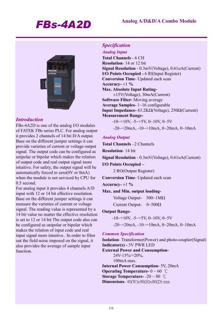
Introduction<br />
<strong>FBs</strong>-<strong>4A2D</strong> is one of the analog I/O modules<br />
of FATEK <strong>FBs</strong> series PLC. For analog output<br />
it provides 2 channels of 14 bit D/A output.<br />
Base on the different jumper settings it can<br />
provide varieties of current or voltage output<br />
signal. The output code can be configured as<br />
unipolar or bipolar which makes the relation<br />
of output code and real output signal more<br />
intuitive. For safety, the output signal will be<br />
automatically forced to zero(0V or 0mA)<br />
when the module is not serviced by CPU for<br />
0.5 second.<br />
For analog input it provides 4 channels A/D<br />
input with 12 or 14 bit effective resolution.<br />
Base on the different jumper settings it can<br />
measure the varieties of current or voltage<br />
signal. The reading value is represented by a<br />
14 bit value no matter the effective resolution<br />
is set to 12 or 14 bit The output code also can<br />
be configured as unipolar or bipolar which<br />
makes the relation of input code and real<br />
input signal more intuitive.. In order to filter<br />
out the field noise imposed on the signal, it<br />
also provides the average of sample input<br />
function.<br />
Specification<br />
Analog Input<br />
Total Channels - 6 CH<br />
Resolution- 14 or 12 bit<br />
Signal Resolution - 0.3mV(Voltage), 0.61uA(Current)<br />
I/O Points Occupied - 6 RI(Input Register)<br />
Conversion Time- Updated each scan<br />
Accuracy- ±1 %<br />
Max. Absolute Input Rating-<br />
±15V(Voltage), 30mA(Current)<br />
Software Filter- Moving average<br />
Average Samples- 1~16 configurable<br />
Input Impedance- 63.2KΩ(Voltage), 250Ω(Current)<br />
Measurement Range-<br />
-10~+10V, -5~+5V, 0~10V, 0~5V<br />
-20~+20mA, -10~+10mA, 0~20mA, 0~10mA<br />
Analog Output<br />
Total Channels –2 Channels<br />
Resolution- 14 bit<br />
Signal Resolution - 0.3mV(Voltage), 0.61uA(Current)<br />
I/O Points Occupied –<br />
2 RO(Output Register)<br />
Conversion Time- Updated each scan<br />
Accuracy- ±1 %<br />
Max. and Min. output loading-<br />
Voltage Output- 500~1MΩ<br />
Current Output- 0~500Ω<br />
Output Range-<br />
-10~+10V, -5~+5V, 0~10V, 0~5V<br />
-20~+20mA, -10~+10mA, 0~20mA, 0~10mA<br />
Common Specification<br />
Isolation- Transformer(Power) and photo-coupler(Signal)<br />
Indicator(s) - 5V PWR LED<br />
External Power and Consumption-<br />
24V-15%/+20%,<br />
100mA max.<br />
Internal Power Consumption- 5V, 20mA<br />
Operating Temperature- 0 ~ 60 ℃<br />
Storage Temperature- -20 ~ 80 ℃<br />
Dimensions- 40(W)x90(H)x80(D) mm<br />
1/6
<strong>FBs</strong>-<strong>4A2D</strong><br />
Analog A/D&D/A Combo Module<br />
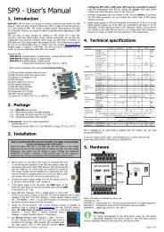
Dimensions<br />
Wiring Diagram<br />
<strong>FBs</strong>-<strong>4A2D</strong><br />
<strong>FBs</strong>-4DA/2DA<br />
Output<br />
+15V<br />
15V<br />
24V+<br />
24V<br />
+ 24VDC<br />
External power supply<br />
V<br />
O0+<br />
CH0 Output ( Voltage Source )<br />
V+<br />
I<br />
O0<br />
V<br />
FG<br />
Voltage Input<br />
AG<br />
V<br />
O1+<br />
CH1 Output ( Current Source )<br />
I+<br />
I<br />
O1<br />
I<br />
Twisted Pair with shielding<br />
FG<br />
Current Input<br />
Voltage / Current<br />
selection<br />
Inputs<br />
V<br />
I<br />
I0+<br />
I0<br />
V<br />
CH0 Input<br />
( Voltage source )<br />
V<br />
I<br />
I1+<br />
I1<br />
I<br />
CH1 Input<br />
( Current sourvce )<br />
AG<br />
I<br />
V<br />
I3+<br />
I3<br />
V<br />
CH5 Input<br />
( Voltage source )<br />
Voltage / Current<br />
selection<br />
Twisted Pair with shielding<br />
2/6
<strong>FBs</strong>-<strong>4A2D</strong><br />
Analog A/D&D/A Combo Module<br />
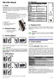
D/A Jumper Setup<br />
Output Code Format Selection<br />
There are two formats of output code can be selected, one is Unipolar and the other is Bipolar. The range<br />
of the Unipolar code value is 0~16383 while the Bipolar is –8192~8191. The extreme two ends of the<br />
code value corresponding to the minimal and maximal analog output level respectively. For example, if<br />
the analog signal is set to –10V~+10V range, for the same code value 0, the Bipolar code will result 0V<br />
output, while the Unipolar code will result –10V output, for the code value 8191, the Bipolar code will<br />
result 10V output, while the Unipolar code will result 0V output. The JP1 are shared for CH0, CH1 which<br />
means both channels can not configure to different output code format.<br />
Format JP1 Code Range Corresponding Output<br />
Bipolar<br />
Unipolar<br />
-8192~8191<br />
0~16383<br />
-10V~10V(-20mA~20mA)<br />
-5V~5V(-20mA~20mA)<br />
0V~10V(0mA~20mA)<br />
0V~5V(0mA~10mA)<br />
JPB<br />
DA0<br />
JPA<br />
DA1<br />
JP3<br />
JP4<br />
JP1<br />
JP5~JP8<br />
3/6
<strong>FBs</strong>-<strong>4A2D</strong><br />
Analog A/D&D/A Combo Module<br />
Output Signal Type Selection<br />
Please refer the above picture for the location of JPA & JPB. The upper row of JPA & JPB is for CH0<br />
D/A, while the second row of JPA & JPB is for CH1 D/A.<br />
Signal Type<br />
0V~10V<br />
JPA (Voltage/Current)<br />
Setup<br />
JPB (Range&Polarity)<br />
Setup<br />
-10V~10V<br />
0V~5V<br />
-5V~5V<br />
0mA~20mA<br />
-20mA~20mA<br />
V<br />
I<br />
0mA~10mA<br />
-10mA~10VmA<br />
4/6
<strong>FBs</strong>-<strong>4A2D</strong><br />
Analog A/D&D/A Combo Module<br />
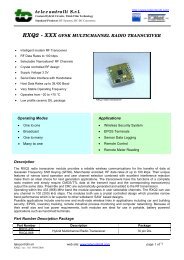
A/D Jumper Setup<br />
Input Code Format Selection<br />
There are two input data formats can be selected which are bipolar and unipolar. The range of input value<br />
is 0~16383 for unipolar format while bipolar is -8192~8191. The two extreme values of each range<br />
corresponding to the minimal and maximal input signal. For example, if chose the -10V~+10V type<br />
signal, for 10V input signal the input value is 16383 for unipolar format while the bipolar format is 8191.<br />
Normally the input code format setting is consistent with input signal type (bipolar coded for bipolar<br />
input signal, unipolar coded for unipolar input signal). Only when use the FUN32 for offset conversion<br />
should set the bipolar code for unipolar input signal (Please refer the FUN32 description). The code<br />
format of all input channels are set by the same JP1 jumper. The location and the setting of jumper of JP1<br />
are shown at below<br />
Code<br />
Format<br />
JP1 Setup Code Range Corresponding Input<br />
Bipolar<br />
JP1 (A/D) -8192~8191<br />
-10V~10V(-20mA~20mA)<br />
-5V~5V(-20mA~20mA)<br />
0V~10V(0mA~20mA)<br />
Unipolar JP1 (A/D) 0~16383<br />
0V~5V(0mA~10mA)<br />
Voltage/Current input signal type setting<br />
Signal Type<br />
JP5 ~ JP8<br />
Voltage<br />
Current<br />
I<br />
V<br />
5/6
<strong>FBs</strong>-<strong>4A2D</strong><br />
Analog A/D&D/A Combo Module<br />
A/D Signal Type selection<br />
Signal Type Polarity Setting (JP3) Range Setting (JP4)<br />
0~10V<br />
or<br />
0~20mA<br />
0~5V<br />
or<br />
0~10mA<br />
-10~+10V<br />
or<br />
-20~+20mA<br />
-5~+5V<br />
or<br />
-10mA~+10mA<br />
U<br />
B<br />
The default factory settings of <strong>4A2D</strong> analogue input/output module are<br />
Input code format – Bipolar(-8192~+8191)<br />
Input signal type and range – Bipolar(-10V ~ +10V)<br />
Output code format – Bipolar(-8192~+8191)<br />
Output signal type and range – Bipolar(-10V ~ +10V)<br />
For those applications that require the setting differ than the above default setting should make some<br />
modifications of jumper position according to above tables.<br />
While application, besides the setting of jumper should be conducted, the AI module configuration of<br />
Winproladder also need to be performed.<br />
6/6