rxq2 - xxx gfsk multichannel radio transceiver - Micropik
rxq2 - xxx gfsk multichannel radio transceiver - Micropik
rxq2 - xxx gfsk multichannel radio transceiver - Micropik

Create successful ePaper yourself
Turn your PDF publications into a flip-book with our unique Google optimized e-Paper software.
telecontrolli S.r.l.<br />
Custom Hybrid Circuits, Thick Film Technology<br />
Standard Products: RF Systems, DC/DC Converters<br />
http://www.telecontrolli.com/<br />
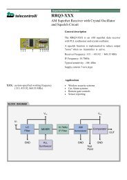
RXQ2 - XXX GFSK MULTICHANNEL RADIO TRANSCEIVER<br />
• Intelligent modem RF Transceiver<br />
• RF Data Rates to 100 kbps<br />
• Selectable ‘Narrowband’ RF Channels<br />
• Crystal controlled RF design<br />
• Supply Voltage 3.3V<br />
• Serial Data Interface with Handshake<br />
• Host Data Rates up to 38,400 Baud<br />
• Very Stable Operating Frequency<br />
• Operates from –20 to +70 °C<br />
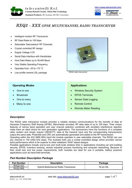
• Low profile ceramic DIL package RXQ2 <strong>radio</strong> <strong>transceiver</strong><br />
Operating Modes<br />
• One to one<br />
• Broadcast<br />
• One to many<br />
• Many to one<br />
Applications<br />
• Wireless Security System<br />
• EPOS Terminals<br />
• Sensor Data Logging<br />
• Remote Control<br />
• Remote Meter Reading<br />
Description<br />
The RXQ2 <strong>radio</strong> <strong>transceiver</strong> module provides a reliable wireless communications for the transfer of data at<br />
Gaussian Frequency Shift Keying (GFSK), Manchester encoded, RF data rates of up to 100 kbps. Their unique<br />
features of narrow band operation and user channel selection combined with excellent interference rejection<br />
make them an ideal choice for next generation applications. The <strong>transceiver</strong>s have the functions of a complete<br />
<strong>radio</strong> modem and simply require CMOS/TTL data at the transmit input and the corresponding <strong>transceiver</strong>(s)<br />
output the same data. Preamble and CRC are automatically generated and added to the RF transmission.<br />
Operating within the 433 (868) MHz band the module operates in user selectable channels. The RXQ2 can use<br />
any channel in 100 (200) kHz steps. The modules both use a crystal controlled design which provides narrow<br />
band performance which is far superior to other wideband ‘SAW’ based designs.<br />
Possible applications include one-to-one and multi-node wireless links in applications including car and building<br />
security, EPOS, inventory tracking, remote industrial process monitoring and computer networking. Because of<br />
their small size and low power requirements, both modules are ideal for use in portable, battery powered<br />
applications such as hand-held terminals.<br />
Part Number Description Package<br />
Part Number Description Package<br />
RXQ2-433<br />
RXQ2-868<br />
Hybrid Multichannel Radio Transceiver<br />
16 pin DIL<br />
telecontrolli srl web site: www.telecontrolli.com page 1 of 7<br />
RXQ2 : rev. 1.01 09/06/2006
telecontrolli S.r.l.<br />
Custom Hybrid Circuits, Thick Film Technology<br />
Standard Products: RF Systems, DC/DC Converters<br />
http://www.telecontrolli.com/<br />
Pinout & Mechanical Details<br />
Pin Descriptions<br />
Pin<br />
Number<br />
Name Type Description<br />
1 Vcc Power<br />
Positive supply voltage connection. Decouple with 100nF ceramic capacitor<br />
to ground<br />
2,3,4,6 GND Power Connect to 0 volts<br />
5 Antenna In / Out<br />
Nominal 50 Ohm input/output impedance capacitively isolated from the<br />
internal circuit<br />
7,8 n.c. --- No connection<br />
9 PD In Power Down pin. Ground : Power Down Mode; +Vcc : Operating Mode<br />
10 TX (UART) In<br />
Transmit data input from host controller.<br />
Data input to the transmitter can be directly interfaced to CMOS logic drive<br />
operating on the same supply voltage as the <strong>transceiver</strong>.<br />
Serial port setup : 1 start, 8 bit, 1 stop, no parity<br />
11 RX (UART) Out<br />
Received data output to host controller (CMOS logic out) representing true<br />
data as supplied to the transmitter.<br />
Serial port setup : 1 start, 8 bit, 1 stop, no parity<br />
12,13 Data Rate In Host Data Rate selection (see next table)<br />
14 Configuration In Ground : Configuration mode; +Vcc : Operating mode.<br />
5 RTS In<br />
Logic ‘0’ is Request To Send.<br />
Take low when the host is ready to send data to the module or is ready to<br />
receive data from the module.<br />
6 CTS Out<br />
Logic ‘0’ is Clear To Send.<br />
Taken high when the module is busy.<br />
Host Data Rate Selection<br />
DR1 (pin 12) DR2 (pin 13) Baud Rate<br />
Gnd Gnd 4,800<br />
Vcc Gnd 9,600<br />
Gnd Vcc 19,200<br />
Vcc Vcc 38,400<br />
telecontrolli srl web site: www.telecontrolli.com page 2 of 7<br />
RXQ2 : rev. 1.01 09/06/2006
telecontrolli S.r.l.<br />
Custom Hybrid Circuits, Thick Film Technology<br />
Standard Products: RF Systems, DC/DC Converters<br />
http://www.telecontrolli.com/<br />
Technical Specifications<br />
• Absolute Maximum Rating<br />
Operating temperature: -20 °C to +80 °C<br />
Storage temperature: -40 °C to +100 °C<br />
Supply Voltage: 1.9V to 3.6V<br />
Data input/output:<br />
-0.3V to Vcc+0.3V<br />
• Electrical Characteristics<br />
Min. Typ. Max. Units Notes<br />
DC Levels<br />
Supply voltage 1.9 3.3 3.6 V 1<br />
Supply current (Transmit mode) 11 30 mA<br />
Supply current (Receive mode) 12.5 mA<br />
Supply current (power down mode) 125 uA<br />
Data input/output high Vcc-0.3 Vcc V<br />
Data input/output low 0 0.3 V<br />
RF<br />
Working frequency : RXQ2-433<br />
430.0<br />
440.0<br />
RXQ2-868<br />
860.0<br />
880.0<br />
MHz 2<br />
Receiver sensitivity -100 dBm<br />
Transmitter RF power out +10 dBm<br />
Frequency deviation +/-50 kHz<br />
GFSK Manchester encoded data rate 100 kbps<br />
Operating temperature -20 +70 °C<br />
Dynamic Timing<br />
Power up to stable receiver data out 30 msec<br />
Power up to full RF out 30 msec<br />
Standby to Receive mode 1 msec<br />
Standby to Transmit mode 1 msec<br />
Notes<br />
1. Supply voltage should have
telecontrolli S.r.l.<br />
Custom Hybrid Circuits, Thick Film Technology<br />
Standard Products: RF Systems, DC/DC Converters<br />
http://www.telecontrolli.com/<br />
Applications<br />
The RXQ2 wireless module has applications in many areas where reliable half duplex communications are<br />
required over ranges up to 200 meters. The crystal controlled narrow band design, in the embedded RXQ2<br />
<strong>transceiver</strong>, gives reliable performance within the 433 (868) MHz band.<br />
The addressing protocol employed enables many different configurations such including:<br />
one-to-one operation: for point to point data communication;<br />
broadcast operation: where a single master address many RXQ2 modules concurrently (using many RXQ2<br />
modules set to the same address);<br />
one-to-many: a network consisting a master and many slaves (the receivers all have the same address)<br />
many-to-one: where the transmitters all send to a single receiver address<br />
Because each RXQ2 can contain a unique address, multiple RXQ2 network can co-exist in the same area.<br />
Operation<br />
The Host Data Rate pins (12,13) are read when the PD switch goes high (pin 14 = Vcc). The RXQ2 must be put<br />
into standby mode by taking the PD pin low (pin 14 = GND) in order to change the selection.<br />
The size of RF data packets are set during configuration. If fewer bytes are received by the RXQ2 <strong>transceiver</strong><br />
than the preset size, then after 10ms from the last byte received from the host, the RF packet will be processed<br />
(expanded to meet the preset packet size) and transmitted. The RF data packet size must be set the same for<br />
transmitter and receiver, otherwise the received packets will be discarded.<br />
In order to optimize data rate , in a point-to-point configuration where data is mostly being sent in one direction,<br />
the packet size for one data direction can be set to the maximum size, however the reverse direction may be set<br />
to a smaller packet size, to implement an acknowledge reply for example.<br />
The RTS pin overrides the timeout value. If a short data packet is sent, RF transmission will start as soon as the<br />
RTS pin is taken ‘high’ after the last byte is sent to the module.<br />
The RXQ2 contains an on-board data buffer equal to two data packets. Therefore if RTS is asserted (then the<br />
host is unable to receive data) the RXQ2 will store a max of two data bytes, all further data packets received will<br />
be discarded.<br />
No RF packets will be received by the module when it is in power down mode.<br />
Each RXQ2 has its own preset address. This is set during configuration. Any data received is examined and the<br />
address header, embedded within the data packet, is compared with the RXQ2 address. Only data received with<br />
matching address will be processed and output to the host, all other data will be discarded.<br />
All RXQ2 modules are shipped with a default address of 7E7E7E7E.<br />
telecontrolli srl web site: www.telecontrolli.com page 4 of 7<br />
RXQ2 : rev. 1.01 09/06/2006
telecontrolli S.r.l.<br />
Custom Hybrid Circuits, Thick Film Technology<br />
Standard Products: RF Systems, DC/DC Converters<br />
http://www.telecontrolli.com/<br />
RXQ2 configuration<br />
The configuration of the RXQ2 module may be changed by setting the Configuration switch low (Pin 14 = GND)<br />
and sending a set of configuration data bytes to the module on TX pin.<br />
Byte Name Description Default Value (hex)<br />
0 MSB 7E<br />
1 7E<br />
Destination Address<br />
2 7E<br />
3<br />
LSB<br />
7E<br />
4 MSB 7E<br />
5 7E<br />
RXQ2 Address<br />
6 7E<br />
7<br />
8 RF Channel<br />
9 Tx Power<br />
LSB<br />
100 kHz step (RXDL1-433)<br />
200 kHz step (RXDL1-868)<br />
00 = -10 dBm<br />
01 = -2 dBm<br />
02 = +6 dBm<br />
7E<br />
6B (433,1 MHz)<br />
75 (868,2 MHz)<br />
03 = +10 dBm<br />
10 Tx data packet size 1E (30 bytes)<br />
11 Rx data packet size 1E (30 bytes)<br />
The RF Channel is calculated as:<br />
433 MHz working frequency : Configuration value (decimal) = (desired RF frequency - 422.4MHz) * 10<br />
00<br />
868 MHz working frequency : Configuration value (decimal) = [(desired RF frequency / 2) - 422.4MHz] * 10<br />
Note : calculated value must be converted into hexadecimal format.<br />
The Configuration pin (Pin 14) must be held low (ground) for at least the first byte to change the RXQ2 module<br />
into configuration mode. If the Configuration pin is still low at the end of the configuration then the module will<br />
send the current configuration back to the host. To retrieve the current configuration without changing any options<br />
the host can send a single byte to the module and wait for the response.<br />
It is not necessary to send all configuration bytes to the module, but all data sent must be valid. For example to<br />
change the destination address the host may just send four bytes. Configuration data excluded from the end of<br />
the data stream will be unchanged. The RXQ2 module will accept a short configuration after a 10ms timeout after<br />
the last byte sent to the module, or when the RTS pin goes high. This allows for the host to easily change the<br />
destination address of the RF data packet, thus enabling one RXQ2 to send individual data to several different<br />
recipient modules.<br />
A destination address of 00000000 will reset the RXQ2 to the default settings shown above.<br />
RF data packets received by the RXQ2 with the embedded destination address which matches the RXQ2<br />
address will be accepted, processed and passed to the host, all of the RF data packets will be ignored.<br />
When configuring the destination or RXQ2 address an incorrect number of bytes for an address will leave the<br />
current address unchanged. An invalid Transmitter Power or Packet Size setting will leave the current setting<br />
unchanged.<br />
telecontrolli srl web site: www.telecontrolli.com page 5 of 7<br />
RXQ2 : rev. 1.01 09/06/2006
telecontrolli S.r.l.<br />
Custom Hybrid Circuits, Thick Film Technology<br />
Standard Products: RF Systems, DC/DC Converters<br />
http://www.telecontrolli.com/<br />
Application information<br />
Connection of the RXQ2 to an RS232 host terminal device such as a PC serial port may easily be achieved using<br />
the circuit as below. The 9 way ‘D’ socket (J1) provides the standard pinout required to connect directly to the<br />
serial port of any std PC using a 9 way male/female cable. The MAX3232 (U2) provides level conversion between<br />
the RS232 levels on the serial port and the logic levels pins of the RXQ2 module. (note that direct connection of<br />
RS232 levels to the module will result in immediate destruction of the device).<br />
Antenna<br />
Vcc (3.3V)<br />
1<br />
2<br />
3<br />
4<br />
5<br />
6<br />
7<br />
8<br />
U1<br />
RXQ2<br />
16<br />
15<br />
14<br />
13<br />
12<br />
11<br />
10<br />
9<br />
R1..R4 = 10k<br />
C1..C4 = 100n<br />
1<br />
2<br />
3<br />
4<br />
5<br />
6<br />
7<br />
8<br />
U2<br />
MAX<br />
3232<br />
16<br />
15<br />
14<br />
13<br />
12<br />
11<br />
10<br />
9<br />
1<br />
2<br />
3<br />
4<br />
5<br />
J1<br />
6<br />
7<br />
8<br />
9<br />
Circuit notes:<br />
• Pins 12 and 13 of the RXQ2 (U1) are pulled high via 10K Ohm resistors, this sets a board rate of 38,400<br />
Baud.<br />
• Pin 9 of RXQ2 is pulled high via 10K Ohm resistor to prevent the RXQ2 from going in to power down mode.<br />
• Pin 14 of RXQ2 is pulled high via 10K Ohm resistor to prevent the module from entering configuration.<br />
If two such circuits are constructed then it will be possible to interconnect two PC’s and test out the performance<br />
of the hybrids. When both circuits are powered up it will be necessary for them to have others address in the<br />
“Destination Address” register.<br />
The RXQ2 is programmed through the same RS232 port that is used for sending/receiving data. An RS232<br />
terminal emulator (such as LABVIEW) is an ideal tool. To configure the module you can use “RXQ2_Setting.vi”<br />
(free download from our web site): for further details on configuration program, see also RXDL1 <strong>radio</strong> data link<br />
Datasheet.<br />
Labview is a trade mark of National Instruments<br />
telecontrolli srl web site: www.telecontrolli.com page 6 of 7<br />
RXQ2 : rev. 1.01 09/06/2006
telecontrolli S.r.l.<br />
Custom Hybrid Circuits, Thick Film Technology<br />
Standard Products: RF Systems, DC/DC Converters<br />
http://www.telecontrolli.com/<br />
Antenna Design<br />
The design and positioning of the aerial is as crucial as the module performance itself in achieving a good<br />
wireless system range. The following will assist the designer in maximizing system performance.<br />
The RF ground pin should be connected to a ground plane which should shield the aerial connection and the<br />
PCB layout around the aerial track itself should be such as to give a 50 Ohm impedance. The aerial should be<br />
kept as far away from sources of electrical interference as physically possible. The specified power supply<br />
decoupling capacitors should be placed close to the module as possible and have direct connections to the<br />
relevant pins.<br />
The antenna ‘hot end’ should be kept clear of any objects, especially any metal as this can severely restrict the<br />
efficiency of the antenna to receive power. Earth planes restricting the radiation path of the antenna will also have<br />
the same effect.<br />
The best range will be achieved with either a straight piece of wire, rod or PCB track @ ¼ wavelength Increased<br />
range may be achieved if this ¼ wave antenna is placed perpendicular to and in the middle of a solid earth plane<br />
measuring at least 16cm radius. In this case, the antenna should be connected to the module using 50 Ohm<br />
coaxial cable and the PCB track layout tips given above should be observed.<br />
Helical Antenna<br />
Whip Antenna<br />
RF<br />
RF<br />
34 mm @ 433 MHz 15.5 cm @ 433 MHz<br />
17 turns equally spaced<br />
∅ = 5 mm inside<br />
Helical Antenna<br />
Whip Antenna<br />
RF<br />
RF<br />
20 mm @ 868 MHz 7 cm @ 868 MHz<br />
9.5 turns equally spaced<br />
∅ = 6 mm inside<br />
telecontrolli srl web site: www.telecontrolli.com page 7 of 7<br />
RXQ2 : rev. 1.01 09/06/2006