26114745-GSM-SP9_Users_M... .pdf
26114745-GSM-SP9_Users_M... .pdf
26114745-GSM-SP9_Users_M... .pdf

You also want an ePaper? Increase the reach of your titles
YUMPU automatically turns print PDFs into web optimized ePapers that Google loves.
<strong>SP9</strong> - User’s Manual<br />
1. Introduction<br />
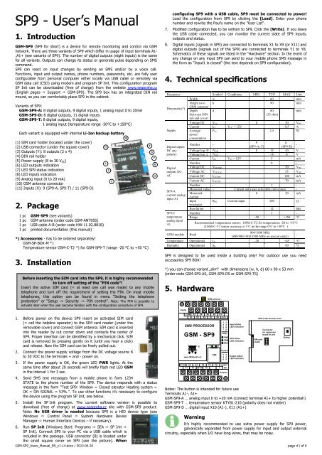
<strong>GSM</strong>-<strong>SP9</strong> (<strong>SP9</strong> for short) is a device for remote monitoring and control via <strong>GSM</strong><br />
network. There are three variants of <strong>SP9</strong> which differ in usage of input terminals A1-<br />
,A1+ (see variants of <strong>SP9</strong>). The number of digital outputs (eight inputs) is the same<br />
for all variants. Outputs can change its status or generate pulse depending on SMS<br />
command.<br />
<strong>SP9</strong> can react on input changes by sending an SMS and/or by a voice call.<br />
Functions, input and output names, phone numbers, passwords, etc. are fully user<br />
configurable from personal computer either locally via USB cable or remotely via<br />
<strong>GSM</strong> data call (CSD) using modem and program SP Init. This configuration program<br />
SP Init can be downloaded (free of charge) from the website www.seapraha.cz<br />
(English pages Support <strong>GSM</strong>-<strong>SP9</strong>). The <strong>SP9</strong> box has an integrated DIN rail<br />
mount, so you can comfortably place <strong>SP9</strong> in the cabinet.<br />
Variants of <strong>SP9</strong>:<br />
<strong>GSM</strong>-<strong>SP9</strong>-A: 8 digital outputs, 9 digital inputs, 1 analog input 0 to 20mA<br />
<strong>GSM</strong>-<strong>SP9</strong>-D: 8 digital outputs, 11 digital inputs<br />
<strong>GSM</strong>-<strong>SP9</strong>-T: 8 digital outputs, 9 digital inputs,<br />
1 analog input (temperature range -50°C to +150°C)<br />
Each variant is equipped with internal Li-Ion backup battery<br />
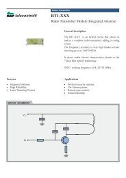
(1) SIM card holder (located under the cover)<br />
(2) USB connector (under the square cover)<br />
(3) Outputs (Y): 8 outputs (2 x 4)<br />
(4) DIN rail holder<br />
(5) Power supply (8 to 30 V DC)<br />
(6) LED outputs indication<br />
(7) LED <strong>SP9</strong> status indication<br />
(8) LED inputs indication<br />
(9) Analog input (0 to 20 mA)<br />
(10) <strong>GSM</strong> antenna connector<br />
(11) Inputs (X): 9 (<strong>SP9</strong>-A, <strong>SP9</strong>-T) / 11 (<strong>SP9</strong>-D)<br />
2. Package<br />
1 pc <strong>GSM</strong>-<strong>SP9</strong> (see variants)<br />
1 pc <strong>GSM</strong> antenna (order code <strong>GSM</strong>-ANT05S)<br />
1 pc USB cable A-B (order code HW-11.02.8818)<br />
1 pc printed documentation (this manual)<br />
*) Accessories - has to be ordered separately!<br />
<strong>GSM</strong>-SP-BOX-M *)<br />
Temperature sensor <strong>GSM</strong>-C-T2 *) for <strong>GSM</strong>-<strong>SP9</strong>-T (range -20 °C to +50 °C)<br />
3. Installation<br />
Before inserting the SIM card into the <strong>SP9</strong>, it is highly recommended<br />
to turn off setting of the “PIN code”!<br />
Insert the active SIM card (= at least one call was made) to any mobile<br />
telephone and turn off the requirement of setting the PIN. On most mobile<br />
telephones, this option can be found in menu “Setting the telephone<br />
protection” or “Setup -> Security -> PIN control”. Note: The PIN is possible to<br />
activate later when the user became familiar with the configuration procedure of <strong>SP9</strong>.<br />
11<br />
1<br />
2<br />
3<br />
10<br />
4<br />
9<br />
8<br />
7<br />
6<br />
5<br />
configuring <strong>SP9</strong> with a USB cable, <strong>SP9</strong> must be connected to power!<br />
Load the configuration from <strong>SP9</strong> by clicking the [Load]. Enter your phone<br />
number and rewrite the Paul's name on the "User List".<br />
7. Modified configuration has to be written to <strong>SP9</strong>. Click the [Write]. If you leave<br />
the USB cable connected, you can monitor the current state of <strong>SP9</strong> inputs,<br />
outputs and status.<br />
8. Digital inputs (signals in <strong>SP9</strong>) are connected to terminals X1 to X9 (or X11) and<br />
digital outputs (signals out of the <strong>SP9</strong>) are connected to terminals Y1 to Y8.<br />
Schematics of these signals are listed in the "Hardware" section. In the event of<br />
any change on any input <strong>SP9</strong> can send to your mobile phone SMS message in<br />
the form as "Input1 is closed" (the text depends on <strong>SP9</strong> configuration).<br />
4. Technical specifications<br />
Parameter Symbol Conditions MIN. TYP MAX Unit<br />
Width w 60 mm<br />
Height (w/o h 90 mm<br />
Dimensions*)<br />
<strong>GSM</strong> antenna)<br />
Depth d 80<br />
mm<br />
(between DIN<br />
(53 slim)<br />
rail and cover)<br />
Voltage DC VCC 8 30 VDC<br />
Current ICC VCC = 12V 0,5 A<br />
Supply Average<br />
power<br />
consumption<br />
PCC 2,5 W<br />
9<br />
11<br />
Digital inputs<br />
DC any<br />
polarity<br />
Digital<br />
outputs DC,<br />
AC<br />
<strong>SP9</strong>-A<br />
current analog<br />
input A1<br />
<strong>SP9</strong>-T<br />
temperature<br />
analog input<br />
A1<br />
Number -<br />
(<strong>SP9</strong>-A,-T)<br />
(<strong>SP9</strong>-D)<br />
-<br />
Voltage log. H |VIN| 8 12 30 V<br />
Voltage log. L |VIN|
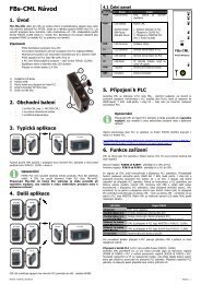
5.1 Digital inputs (X)<br />
Digital inputs (<strong>SP9</strong> input signals) are connected to the input terminal where the COM<br />
terminal is common for all digital inputs X1 to X9 (or X11). The figure shows an<br />
example of the connection of external circuits, and internal wiring of input X1 (same<br />
for all digital inputs). The polarity does not matter - COM can be plus or minus.<br />
<strong>GSM</strong>-<strong>SP9</strong>-D has digital input X10 connected to terminal (A1-) and X11 to A1+.<br />
External<br />
power supply<br />
8 to 30 V DC<br />
Inputs<br />
COM X2 X4 X6 X8 A1-<br />
X1 X3 X5 X7 X9 A1+<br />
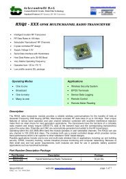
5.2 Digital outputs (Y)<br />
Digital outputs (<strong>SP9</strong> output signals) are connected to the output terminals where the<br />
terminal C1-C4 is common for outputs Y1 to Y4 and the terminal C5-C8 is common<br />
for Y5 to Y8. The figure shows an example of the external and internal wiring<br />
circuits of output Y1 (the same for all digital outputs). Y2 output switches negative<br />
branch power relay coil and vice versa Re2 Y6 output switching power supply<br />
positive branch of the relay coil Re6 (voltage relay must correspond to an external<br />
source voltage!). The polarity of the terminals C1-C4 and C5-C8 terminals is<br />
irrelevant - can be plus or minus.<br />
5.3 Analog Input (<strong>SP9</strong>-A and <strong>SP9</strong>-T only)<br />
<strong>SP9</strong>-A and <strong>SP9</strong>-T versions have 1 analog input, which is connected to the input<br />
terminals (A1+, A1-).<br />
<strong>SP9</strong>-A - Analog input is designed to measure the current 0-20 mA. The measured<br />
value 0-20 mA can be converted to user units. For example the measured current<br />
from 4 to 20 mA can be displayed as the pressure of 0-5 MPa (see the chapter<br />
Configuration - program SP Init).<br />
<strong>SP9</strong>-T - Analog input is designed to measure the temperature -50°C …+150°C<br />
(using KTY 81-210 temperature sensor)<br />
5.4 Front Panel<br />
1 2<br />
3 4<br />
5 6<br />
7 8<br />
IN(X)<br />
PWR<br />
<strong>GSM</strong><br />
ERR<br />
OUT(Y)<br />
1 2<br />
3 4<br />
5 6<br />
External<br />
power supply<br />
8 to 30 V DC<br />
+<br />
C1-C4 Y2 Y4 Y5 Y7 Y8<br />
Y1 Y3 C5-C8 Y6 - +<br />
+<br />
+<br />
Re2<br />
+<br />
Re6<br />
8-30V<br />
DC<br />
Výstupy<br />
Internal wiring<br />
of input X1<br />
Power supply of<br />
<strong>SP9</strong> 8 to 30 V DC<br />
Internal wiring<br />
of output Y1<br />
The front panel of the <strong>SP9</strong> includes <strong>SP9</strong> status LEDs and inputs and<br />
outputs status LEDs. The state is only shown for inputs X1 to X8 and all<br />
outputs Y1 to Y8 (LED for Y7 and Y8 are located above the USB connector).<br />
Under the removable cover is placed SIM card reader, the button<br />
(intended for future use) and a connector for connecting of expansion<br />
board (<strong>GSM</strong>-SP-CB2 or <strong>GSM</strong>-SP-CB5) or unit (<strong>GSM</strong>-SP-EXP).<br />
SIM card is inserted into the reader (cut corner down) and contacts to<br />
center of <strong>SP9</strong>. Proper insertion can be identified by a mechanical click. SIM<br />
card can be removed by pressing gently on it (until a click) and release.<br />
Then the SIM card can be pulled out.<br />
USB connector for PC connection is hidden under the square cover.<br />
Meaning<br />
LED COLOR Dark Light Blink 1x<br />
per 3sec<br />
Power ON<br />
PWR green Power OFF or battery - -<br />
powered<br />
<strong>GSM</strong><br />
ERR<br />
1 to 8<br />
(IN)<br />
1 to 8<br />
(OUT)<br />
blue<br />
red<br />
green<br />
green<br />
no<br />
signal<br />
<strong>SP9</strong> OK:<br />
normal<br />
operation<br />
<strong>GSM</strong><br />
input not<br />
activated<br />
output not<br />
activated<br />
other<br />
<strong>GSM</strong> error<br />
<strong>GSM</strong> OK:<br />
normal<br />
operation<br />
1k<br />
<strong>SP9</strong><br />
3k9<br />
<strong>SP9</strong><br />
0,2A<br />
X1<br />
Inputs<br />
COM<br />
Y1<br />
C1-C4<br />
Blink<br />
Fast 1:1<br />
SIM<br />
problem<br />
Error Error Error<br />
input is<br />
activated<br />
output is<br />
activated<br />
-<br />
- -<br />
card<br />
during<br />
transition time<br />
before input<br />
status is<br />
accepted after<br />
input change<br />
(before SMS<br />
can be sent)<br />
6. Remote Control<br />
6.1 SMS Message control<br />
<strong>SP9</strong> is controlled via SMS messages of <strong>GSM</strong> network. Command SMS messages are<br />
in form:<br />
[]<br />
Example:<br />
1234 STATE … <strong>SP9</strong> returns an SMS containing status<br />
1234 DOUT1 ON … <strong>SP9</strong> output1 will be switched on. Confirmation SMS will be<br />
returned<br />
1234 DOUT8 PULSE NOBACK … <strong>SP9</strong> pulse on output8 will be generated, no<br />
confirmation message will be sent back<br />
It’s possible to write more commands into one command SMS. For higher readability<br />
separate commands by semicolon “;” inside command use “=”.<br />
1234 OUTPUT0=ON; OUTPUT1=ON; OUTPUT3=PULSE;<br />
Names of inputs and outputs are user definable by SPInit program. Command SMS<br />
may look like this:<br />
1234 GATE=OPEN; HEATING=ON; LAMP=BLINK<br />
6.2 Status SMS Text Message<br />
Whenever command SMS contains valid password, <strong>SP9</strong> always returns status SMS.<br />
Status SMS contains following information:<br />
: = = ...<br />
=<br />
= ... <br />
Status SMS message contains information only about selected inputs and outputs.<br />
Selection is done in configuration program SPInit by checking the appropriate<br />
checkbox.<br />
<strong>SP9</strong> Status SMS<br />
Explanation<br />
Example<br />
Device <strong>SP9</strong>:<br />
Device Name (user configurable)<br />
DIn1=on<br />
Digital Input 1 is on<br />
DIn2=off<br />
Digital Input 2 is off<br />
DOut3=on<br />
Digital Output 3 is on (closed)<br />
Signal=58% <strong>GSM</strong> Signal level in %<br />
7. Configuration<br />
For configuration of <strong>SP9</strong> is used special program call SP Init. This program can be<br />
downloaded free of charge from the website ......... www.seapraha.cz <strong>GSM</strong>-<strong>SP9</strong>.<br />
Program SP Init enables:<br />
<br />
<br />
<br />
<br />
Local configuration of <strong>SP9</strong> from PC via USB cable<br />
Local monitoring of <strong>SP9</strong> from PC via USB cable<br />
Remote configuration of <strong>SP9</strong> from PC via <strong>GSM</strong> network (CSD)<br />
Remote monitoring of <strong>SP9</strong> from PC via <strong>GSM</strong> network (CSD)<br />
Note: No USB driver is needed because<br />
<strong>SP9</strong> is a HID device type. See Windows the<br />
Control Panel System Hardware Device<br />
Manager Human Interface Devices - if<br />
necessary.<br />
After installation (during the first run) of the<br />
configuration program SP Init it is necessary<br />
to select the device variant (<strong>SP9</strong>-A, <strong>SP9</strong>-D,<br />
<strong>SP9</strong>-T).Select expansion unit <strong>SP9</strong>EXP (if connected) or “No extension”.<br />
After connecting the USB cable to <strong>SP9</strong> the proper COM port is selected automatically<br />
(<strong>SP9</strong> has to be powered!). After pressing the [Connect] <strong>SP9</strong> establishes<br />
communication with the PC (see the "Connection: Connected"). Now it is possible to<br />
read, change and write configuration to <strong>SP9</strong> or read it or write to a file on PC.<br />
7.1 SPInit - Tab “General”<br />
In the "General" tab you can set up the PIN for the SIM card, station name, event<br />
after turning on the device and internal inputs.<br />
<strong>GSM</strong>-<strong>SP9</strong>_<strong>Users</strong>_Manual_EN_v1-14.docx / 2013-04-26 page #2 of 6
7.1.1 Initialization<br />
Enter 4 to 8 digit PIN code of<br />
the SIM card which is inserted<br />
in the <strong>SP9</strong> device. (Leave the<br />
PIN field empty if usage of the<br />
PIN code on the SIM card is<br />
disabled).<br />
7.1.2 Response to<br />
STATE<br />
The Station Name identifies<br />
the <strong>SP9</strong> device. This text is<br />
placed at the beginning of every sent SMS message. It’s also possible add items<br />
Show Battery status and Show <strong>GSM</strong> strength to status SMS by checking these items.<br />
power supply. The value “L” means <strong>SP9</strong> is battery powered. Events and state SMS<br />
are configured like for any other digital input.<br />
7.3 SPInit - Tab “Digital Outputs”<br />
On this tab, you can set<br />
configuration of all digital<br />
outputs of <strong>SP9</strong> device.<br />
(These outputs have only<br />
two states: YES – NO).<br />
These texts will appear in<br />
the status SMS.<br />
7.1.3 Special actions<br />
Use button Actions on power supply recovery to specify the text of SMS messages<br />
or voice calls which the <strong>SP9</strong> device sends on startup (see chapter Inputs Events).<br />
7.2 SPInit - Tab “Digital Inputs”<br />
On this tab, you can set<br />
configuration of all digital<br />
inputs of <strong>SP9</strong> device.<br />
(These inputs have only two<br />
states: YES – NO).<br />
These texts will appear in<br />
the status SMS.<br />
Note: Inputs DIn10 and<br />
DIn11 are not available for<br />
the <strong>SP9</strong>-A and <strong>SP9</strong>-T.<br />
7.2.1 Text in Messages<br />
Input Name, State L, State H<br />
These fields contain names of inputs and their possible states, which are listed in<br />
the status SMS message.<br />
Example:<br />
When we assign Input as “Input1”, “State L” as Off and “State H” as On, the part of<br />
SMS status message concerning Input1 will look like this “Input1=On”.<br />
Mention in State SMS<br />
If this box is checked, the status of this input will appear in the status SMS<br />
message.<br />
Remember after turn off<br />
If this box is checked, the digital input state before switching off of the <strong>SP9</strong> will be<br />
remembered. This is important when <strong>SP9</strong> has to send an SMS message (or make<br />
voice calls) and the input state changes during a power on of <strong>SP9</strong>. Details are<br />
provided in analog inputs.<br />
7.2.2 Change Notification<br />
Transition L => H, transition H => L<br />
When the input level is changed than after delay (which is necessary for the<br />
recognition of the input state) the requested action (SMS or voice call) is performed.<br />
Delay (h: m: s)<br />
Specifies how long new input state must be stable before action is executed.<br />
(Note: the delay timers are nonlinear and it may happen that the program adjusts<br />
your choice at the earliest possible time, e.g. 25:0:5 is adjusted to 25:0:0).<br />
Actions<br />
Here is possible to select what SMS messages or calls the device has to send when<br />
the status changes (see "Events at the inputs").<br />
Actions (SMS or voice calls) to be done on the transition of input signal. (See the<br />
chapter “Inputs Events“).<br />
Negate<br />
If this box is checked, the meaning of states L (inactive) and H (active) is opposite.<br />
7.2.3 Internal input "PWW" - power<br />
<strong>SP9</strong> has an internal digital input PWW (internally X12 input e.g. for MACRO), which<br />
monitors the supply voltage. The value “H” means the <strong>SP9</strong> is powered from external<br />
7.3.1 Text in Messages<br />
Output Name, State L, State H<br />
These fields contain names of outputs and their possible states, which are listed in<br />
the status SMS message.<br />
Example:<br />
If you name the Output “Output1”, Status L “Off” and Status H “On”, than you will<br />
see the following text in the status SMS: "Output1 = Off".<br />
Mention in State SMS<br />
If this box is checked, the status of this output will appear in the status SMS.<br />
Startup<br />
After power on, the <strong>SP9</strong> can set an output to "State L", "State H" or retain the<br />
status output that was before power off (option "Remember").<br />
7.3.2 Impulses<br />
Command<br />
The text used in the command SMS for generating of a pulse on the output (e.g.<br />
"pulse").<br />
Duration (h: m: s)<br />
Specifies duration of the output pulse.<br />
(Note: the duration timers are nonlinear and it may happen that the program<br />
adjusts your choice at the earliest possible time, e.g. 25:0:5 is adjusted to 25:0:0).<br />
Negate<br />
If this box is checked, the meaning of states L (inactive) and H (active) is opposite.<br />
7.4 SPInit - Tab “Analog Inputs”<br />
On this tab is selected configuration for analog input A1 variant <strong>SP9</strong>-A and <strong>SP9</strong>-T.<br />
7.4.1 Text in Messages<br />
Analog Input Name<br />
These fields contain names of<br />
inputs and their possible states,<br />
which are listed in the status<br />
SMS message.<br />
Example:<br />
When we assign Input A1 as<br />
“Current” and check the “Zone”<br />
and “Value”, the part of SMS<br />
status message concerning input<br />
A1 will look like this<br />
“Current=High 20mA” for<br />
example.<br />
Mention in state message<br />
If this box for Zone and/or Value is checked, the Zone and/or Value of this analog<br />
input will appear in the status SMS message.<br />
Filter constant<br />
For each analog input is possible to set by the filter value in range 0.2 sec to 30 sec<br />
or without filter.<br />
Remember after turn off<br />
<strong>GSM</strong>-<strong>SP9</strong>_<strong>Users</strong>_Manual_EN_v1-14.docx / 2013-04-26 page #3 of 6
If this box is checked, analog input value and zone state will be remembered before<br />
shut down of <strong>SP9</strong>. After power on of <strong>SP9</strong> the actual value and zone is compared<br />
with stored value and zone and the SMS message is send or not send depending on<br />
the change.<br />
(Actions and settings)<br />
Here is possible to select what SMS messages or calls the <strong>SP9</strong> device will send send<br />
when the analog inputs status changes (see "Events at the inputs" for details).<br />
7.5 SPInit - Tab “User List”<br />
Device SP6 has one central user list. For any action a user is chosen from this<br />
central user list.<br />
7.5.1 Existing users<br />
Phone number<br />
User phone number which<br />
is used for sending SMS<br />
messages or voice calls for<br />
this user.<br />
Attention: Authorization of<br />
incoming messages does<br />
not depend on the phone<br />
number - the phone<br />
number is used only for<br />
sending SMS (or voice<br />
call)!<br />
Name<br />
User name. This area is<br />
not used by <strong>SP9</strong> device. It is useful for better orientation in list.<br />
Code<br />
User code. This code is used for authorization of incoming command messages.<br />
Received SMS are executed only if it contains “code” of some user in your user list.<br />
Message prefix<br />
The text which is added in front of SMS message for this user. It is used for sending<br />
messages e.g. at e-mail. This message is usually sent on special phone number (e.g.<br />
4616) and first in message is an e-mail address.<br />
Pulse on Call<br />
The voice call from user’s phone number results into pulse on the selected output<br />
(Dout1 to Dout8). Select item “-“ for no pulse. The pulse duration can be set in the<br />
“Digital Outputs” in area Impulses.<br />
7.5.2 Lists<br />
<strong>Users</strong> who get copy of all STATUS responses<br />
Choose users, to whom the copy of status massage is sent whenever any status<br />
message is about to send.<br />
7.6 SPInit - Tab “Advanced”<br />
On this tab are placed special advanced features of the <strong>SP9</strong>.<br />
7.6.1 Automatically repeated actions<br />
Action Group A, Action Group B<br />
Allows you to specify the time period after which <strong>SP9</strong> executes the specified list of<br />
events. This is useful e.g. for automatic reporting that the device is functional and<br />
can communicate via <strong>GSM</strong> network. This feature is called "alive".<br />
7.6.2 On problems with sending SMS<br />
Specifies how many attempts to send an SMS are made when any problem appears<br />
in <strong>GSM</strong> network. The range is 1 to 31 attempts.<br />
7.6.3 On problems with Voice call<br />
Specifies how many attempts of voice call are made when any problem appears in<br />
<strong>GSM</strong> network. The limit range is 1 to 31 attempts.<br />
7.6.4 Expert modem setting<br />
Service center (SCA)<br />
Leave empty. It is intended for users, who have special Service center.<br />
Initialization commands<br />
Specifies AT commands, which the device sends into the <strong>GSM</strong> modem at startup.<br />
ATTENTION! Commands in this field may cause malfunction of the device. Enter<br />
commands only after consultation with the manufacturer of the device!<br />
7.6.5 Indication of device readiness<br />
Indication on Dig. Output<br />
Selected output is on when the <strong>SP9</strong> is connected to <strong>GSM</strong> network. This function is<br />
typically used when indication of <strong>GSM</strong> connection is necessary.<br />
7.7 SPInit - Tab “SP-CB” (<strong>SP9</strong>-T)<br />
Tab “SP-CB” (<strong>SP9</strong>-T) is intended for special purposes only<br />
7.8 SPInit - Tab “Monitoring”<br />
Program SPInit enables to watch<br />
status of inputs and outputs on<br />
PC monitor in tab “Monitoring”.<br />
Monitoring can be local via USB<br />
cable or remote via <strong>GSM</strong> data<br />
connection (CSD). It’s possible<br />
to switch on or off digital<br />
outputs by clicking on<br />
pushbutton [Change] or [Pulse].<br />
It helps to check function of<br />
external circuitry.<br />
7.8.1 Operational<br />
status<br />
List of actual information concerning the <strong>SP9</strong> device and it’s functioning.<br />
Automaton state Information for service purposes only<br />
Signal strength <strong>GSM</strong> signal level in %<br />
<strong>GSM</strong> operator Actual <strong>GSM</strong> operator’s name<br />
7.8.2 Digital inputs, outputs and analog inputs<br />
List of actual status of all digital inputs, outputs and analog inputs.<br />
Terminal<br />
The terminal name<br />
Unfiltered<br />
Measured values of the inputs or outputs of the device are<br />
usually filtered to avoid often change of state. In this box you will find the real value<br />
of the input device. This is useful especially when the delay is set to a larger<br />
transition time, e.g. 1 hour.<br />
Name<br />
Name of input or output<br />
Value<br />
Analog input value<br />
Zone<br />
Analog input zone (e.g. low, high)<br />
Age<br />
Input values are not updated immediately. Depending on<br />
CPU values may be delayed up to 20 seconds. This field will show when an item has<br />
been measured last time.<br />
When any output is selected, it’s possible to use the right mouse button to change<br />
the status and generate a pulse. This is useful for testing the function of the<br />
external circuits connected to <strong>SP9</strong>. Please be patient after pressing – the change of<br />
output may take some time (e.g. 20 seconds when connected via <strong>GSM</strong>).<br />
<strong>GSM</strong>-<strong>SP9</strong>_<strong>Users</strong>_Manual_EN_v1-14.docx / 2013-04-26 page #4 of 6
7.9 SPInit - Important Terms Explanation<br />
PIN (Personal Identification Number – usually four digits number). Only persons<br />
with knowledge of PIN can operate a SIM card (in case the PIN usage on a SIM card<br />
was activated). Usage of the PIN can be deactivated. Insert the SIM card to your<br />
mobile phone and follow the instruction in the mobile phone manual. (Usually the<br />
PIN usage can be deactivated in Menu -> Security -> PIN).<br />
ACCESS CODE = Password for SMS commands, configuration and monitoring of<br />
<strong>SP9</strong> accepts only SMS with a valid access code. The password is requested also for<br />
connection of <strong>SP9</strong> (via USB cable or remotely via data connection of <strong>GSM</strong> network).<br />
Factory setting of access code is “1234”.<br />
EVENT = level change in case of digital input, zone change in case of analog inputs.<br />
<strong>SP9</strong> can react on EVENTS by several ACTIONS if it is setup this way. <strong>SP9</strong> can send<br />
SMS messages on selected phone numbers and/or to make voice calls on selected<br />
phone numbers.<br />
ACTION = one voice call or one SMS to one user. Any EVENT can contain several<br />
ACTIONS.<br />
USER LIST = List of all users and their phone numbers which are used for<br />
ACTIONS. User names are used only for better clarity. <strong>SP9</strong> does not use them in any<br />
way.<br />
DEVICE OFF = Disconnection of <strong>SP9</strong> from any form of power supply (including<br />
internal battery).<br />
Here it is possible to select the format of the values (not for internal inputs), which<br />
used for displaying and the unit values.<br />
Conversion<br />
In this table, you can specify your own conversion of input values to be displayed<br />
(not for internal inputs)<br />
In the tab "Zones and<br />
events" can be set the<br />
name of the zone and the<br />
limit value with hysteresis.<br />
Whenever the actual value<br />
is inside the zone, the zone<br />
name is displayed in the<br />
status SMS message.<br />
Furthermore is possible to<br />
set up the action which will<br />
be executed after the input<br />
level transition (above or<br />
below a certain level) after<br />
a specified delay. Setting of<br />
actions and macros is the<br />
same as for the digital<br />
inputs<br />
DEVICE ON = Connection of <strong>SP9</strong> to any form of power supply. (Processor reset has<br />
the same effect).<br />
POWER ON/OFF = Connection/disconnection of supply terminals from external<br />
power supply. (<strong>SP9</strong> supplied from internal battery can send SMS about Power<br />
recovery and Power outage).<br />
7.10 Remote Configuration<br />
<strong>SP9</strong> can be configured remotely via <strong>GSM</strong><br />
data connection (CSD) in the same way<br />
like via USB cable (Note: You need any<br />
<strong>GSM</strong> modem connected to your PC). Just<br />
click in menu [Options] and in new<br />
window called “Options” set the “Station’s<br />
phone” number for data connection to<br />
<strong>SP9</strong>. Click [OK] to close the window. For<br />
connection select proper COM port which<br />
is used for communication with modem<br />
and press the button [Connection]. Confirm the phone<br />
number [Yes]. When the <strong>GSM</strong> connection is established it’s<br />
possible to operate the <strong>SP9</strong> in the same way like via USB.<br />
Note: Press [Disconnect] when your task is finished.<br />
Example:<br />
Sample configuration with<br />
the analog input values<br />
conversion to user units:<br />
Analog input is configured<br />
as current input 0-20 mA.<br />
Pressure sensor gives 4 mA<br />
at 0 MPa and 20 mA at 10<br />
MPa (see settings in the<br />
picture).<br />
A/D<br />
Converter<br />
Range<br />
MAX<br />
Zone<br />
HIGH<br />
User<br />
Units<br />
100 kPa<br />
Event SMS<br />
(user defined text)<br />
Increase Over Critical Level!<br />
Decrease on Operational Level.<br />
Status SMS<br />
Name Zone<br />
X<br />
Value<br />
X<br />
PRESSURE HIGH 71kPa<br />
PRESSURE MIDDLE 69kPa<br />
7.11 Events<br />
<strong>SP9</strong> can be set up to inform about events (= changes) on its digital and analog<br />
inputs. <strong>SP9</strong> sends information via SMS message or makes a voice call. By the SPInit<br />
program is possible to set several actions for each event specifying the phone<br />
number – user who will receive an SMS message and who will be called. A various<br />
SMS can be sent to and a voice call can be made to more phone numbers from the<br />
list. The order of SMS and voice calls depends on a list of actions for each action.<br />
Voice call rises the probability the user will not miss received SMS message.<br />
7.11.1 How to create an Event<br />
First of all the Event has to be created in the configuration program SP Init. Click by<br />
a mouse on the symbol of a key . By pushbutton [+ ADD] select requested<br />
action of <strong>SP9</strong> (SMS or voice call), write the text of SMS which has to be sent or<br />
insert the sequence of DTMF numbers in case of a voice call. Now select a user and<br />
add him to a list of users for this event by a click on an arrow [>>]. Please check<br />
carefully the number of<br />
users for an event. In case<br />
the number of users is zero<br />
nothing will happen (no<br />
SMS will be sent).<br />
An event for the analog<br />
input can be created in the<br />
folder Analog inputs. Click<br />
by mouse on the symbol<br />
key . In the "Type and<br />
conversion" can be set:<br />
Input type<br />
Note: Analog input A1 is<br />
current type 0-20 mA (<strong>SP9</strong>-<br />
A) or temperature (<strong>SP9</strong>-T)<br />
and cannot be changed.<br />
User units<br />
Input<br />
Value<br />
MIN<br />
7.11.2 Macros<br />
Macros are useful when you need to get values or input and output states in event<br />
or status SMS messages.<br />
Macro Meaning Example<br />
[DINx NAME] Digital input name Input1<br />
[DINx VALUE] Digital input state On<br />
[DOUTx NAME] Digital output name Output1<br />
[DOUTx VALUE] Digital output state Off<br />
[AIN1 NAME] Analog input name Pressure<br />
[AIN1 VALUE] Analog input value 20<br />
[AIN1 STATE] Analog input zone Low<br />
[BAT] Battery charge level in % 75%<br />
[SIGNAL] <strong>GSM</strong> signal level in % 68%<br />
[STATION] Station name <strong>SP9</strong><br />
Use the following numbers instead of letter “x”:<br />
1-11 in Dinx ... as the number of digital input<br />
1-8 at DOutx ... as the number of digital output<br />
Example:<br />
MIDDLE<br />
LOW<br />
0 kPa<br />
Increase on Operational Level.<br />
Decrease below Operational Level!<br />
PRESSURE MIDDLE 31kPa<br />
PRESSURE LOW 29kPa<br />
Event SMS prepared in configuration:<br />
Alarm! Details: [DIN1 NAME] = [DIN1 VALUE], [DIN5 NAME] = [DIN5 VALUE],<br />
[AIN1 NAME] = [AIN1 VALUE] / [AIN1 STATE], Battery = [BAT] %, Signal =<br />
[SIGNAL]<br />
An incoming SMS message:<br />
Office: Alarm! Details: Door = open, Safe = Ok, Pressure = 0.2Pa/Low, Battery =<br />
75%, Signal = 68%<br />
<strong>GSM</strong>-<strong>SP9</strong>_<strong>Users</strong>_Manual_EN_v1-14.docx / 2013-04-26 page #5 of 6
8. Troubleshooting<br />
Problem Possible reason Solution<br />
Problems during No power supply<br />
Check power supply<br />
installation of <strong>SP9</strong><br />
Bad or not activated SIM<br />
card<br />
<strong>SP9</strong> is not<br />
available on <strong>GSM</strong><br />
network<br />
Problems during<br />
operation of <strong>SP9</strong><br />
Low credit on prepaid<br />
SIM card<br />
Low level of <strong>GSM</strong> signal<br />
Low credit on prepaid<br />
SIM card<br />
Prepaid SIM card is no<br />
longer valid because<br />
credit was not paid for<br />
long time. Usually for<br />
more than a year.<br />
Other reason<br />
Test the SIM card in your<br />
mobile phone<br />
Check the credit on prepaid<br />
SIM card (contact your<br />
operator if necessary)<br />
Check the connection of<br />
<strong>GSM</strong> antenna.<br />
Check the <strong>GSM</strong> signal level<br />
in the place where is located<br />
<strong>GSM</strong> antenna for <strong>SP9</strong> (Use<br />
your mobile phone with SIM<br />
card from <strong>SP9</strong>). Signal level<br />
has to be at least two bars.<br />
Check the credit on prepaid<br />
SIM card (contact your<br />
operator if necessary)<br />
Test the SIM card in your<br />
mobile phone.<br />
Test the SIM card in your<br />
mobile phone. (Sending,<br />
receiving SMS, voice call,<br />
data call).<br />
9. Frequently Asked Questions<br />
1. What is necessary to use <strong>SP9</strong> successfully?<br />
SIM card capable to send and receive SMS messages from standard<br />
mobile phone and voice / data call incoming and outgoing as well.<br />
Please test all these functions in your mobile phone. It’s important to<br />
solve all possible problems before using SIM card in <strong>SP9</strong>. Contact your<br />
mobile operator if necessary.<br />
<br />
<br />
<br />
Good quality <strong>GSM</strong> signal in area of installation of <strong>SP9</strong> (at least 2 bars on<br />
your mobile phone). If there is a problem with <strong>GSM</strong> signal quality, try to<br />
use another type of external antenna, which can be placed in proper<br />
place with better <strong>GSM</strong> signal and which is connected to <strong>SP9</strong> with several<br />
meters long coax cable with SMA connector.<br />
Sufficient Credit (in case of prepaid SIM card)<br />
Cancel all phone calls redirection for a SIM card in <strong>SP9</strong><br />
2. What is a phone number of SCA (SCA = Service Center Address) of my mobile<br />
operator? (It’s not possible to send an SMS)<br />
Contact your mobile operator for this piece of information.<br />
3. I’ve tested <strong>SP9</strong> with my own SIM card. Now I cannot find SMS messages formerly<br />
stored on my SIM card.<br />
SMS from your SIM card were processed by <strong>SP9</strong> and then deleted. They<br />
were very probably canceled due to syntactical error.<br />
4. Where can I find more (and up to date) information?<br />
Search <strong>GSM</strong>-<strong>SP9</strong> product on the website www.seapraha.cz English pages<br />
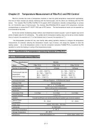
10. <strong>SP9</strong> in box<br />
Special box for <strong>SP9</strong> (order code <strong>GSM</strong>-SP-BOX-M) with power supply (type <strong>GSM</strong>-<br />
PWR1) is produced. Note: This box has to be ordered separately and is designed<br />
only for <strong>SP9</strong> “slim” variant.<br />
Contact your <strong>GSM</strong> (mobile<br />
phone) operator if you have<br />
any problem with SIM card<br />
in your mobile phone.<br />
Vstupy<br />
<strong>GSM</strong> anténa<br />
<strong>SP9</strong> has problem<br />
with SMS sending<br />
Problem with<br />
remote<br />
configuration via<br />
<strong>GSM</strong> modem<br />
SIM card has not active<br />
CSD (Circuit Switched<br />
Data) data<br />
Make a small video of LED<br />
diode blinking on <strong>SP9</strong> and<br />
send it to service.<br />
Check the SCA center<br />
setting on SIM card and in<br />
<strong>SP9</strong> configuration –<br />
program SPInit<br />
Contact your mobile<br />
operator to be sure CSD<br />
data tariff is active for both<br />
SIM cards (in <strong>SP9</strong> and in<br />
Modem).<br />
Note CSD data is not GPRS!<br />
COM X2 X4 X6 X8 A1-<br />
X1 X3 X5 X7<br />
SMS PROCESSOR<br />
<strong>GSM</strong> - <strong>SP9</strong><br />
<strong>GSM</strong>-SP-BOX-M<br />
X9 A1+<br />
1 2<br />
3 4<br />
5 6<br />
7 8<br />
IN(X)<br />
PWR<br />
<strong>GSM</strong><br />
ERR<br />
7 8<br />
OUT(Y)<br />
USB 1 2<br />
www.SEApraha.cz<br />
3 4<br />
5 6<br />
C1-C4 Y2 Y4 Y5 Y7 Y8 8-30V<br />
Y1<br />
Y3<br />
C5-C8<br />
Y6<br />
- +<br />
DC<br />
Výstupy<br />
+ -<br />
12V<br />
POWER<br />
SUPPLY<br />
230V~ / 12V=<br />
<strong>GSM</strong>-PWR1<br />
L<br />
N<br />
Warning<br />
Don’t locate <strong>GSM</strong> antenna too close to <strong>SP9</strong> analog inputs due to possible<br />
noise interference.<br />
<strong>GSM</strong>-SP-BOX-M<br />
Box parameters:<br />
Width: 166 mm<br />
Height: 140 mm (without connectors)<br />
Depth: 87 mm<br />
IP55<br />
230V~<br />
11. Warranty<br />
General warranty period is 12 months after purchase, when eventual malfunction<br />
device will be repaired free of charge in SEA company while shipping to SEA is paid<br />
by customer and SEA pays for shipping back to customer. For SW there is 24<br />
months warranty under following conditions:<br />
Both CPU and PC software is sold “as is”. The software was created by the best<br />
software engineers in SEA and was carefully tested both in SEA and also by SEA<br />
customers using <strong>GSM</strong> applications products made in SEA. In spite of making all<br />
possible to get error free software it can happen, that the software in CPU or PC<br />
programming SW or their mutual interaction has some error under some specific<br />
conditions. If such error is found and the description of the problem including<br />
configuration file is sent by E-mail to SEA ltd., the error is removed free of charge<br />
and SEA will send new SW by E-mail to customer.<br />
SEA ltd. has NO RESPONSIBILITY for any<br />
damage, lost, costs and any other problems direct or inducted,<br />
caused by such SW error, by eventual device malfunction from<br />
any reason or by undelivered SMS from the device.<br />
<strong>GSM</strong>-<strong>SP9</strong>_<strong>Users</strong>_Manual_EN_v1-14.docx / 2013-04-26 page #6 of 6