26114745-GSM-SP9_Users_M... .pdf
26114745-GSM-SP9_Users_M... .pdf
26114745-GSM-SP9_Users_M... .pdf

You also want an ePaper? Increase the reach of your titles
YUMPU automatically turns print PDFs into web optimized ePapers that Google loves.
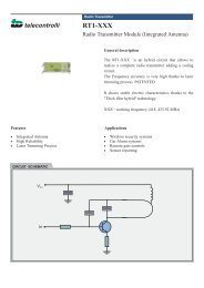
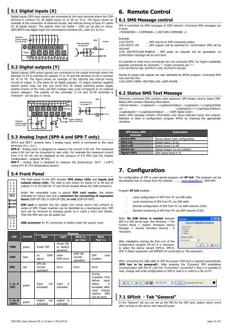
5.1 Digital inputs (X)<br />
Digital inputs (<strong>SP9</strong> input signals) are connected to the input terminal where the COM<br />
terminal is common for all digital inputs X1 to X9 (or X11). The figure shows an<br />
example of the connection of external circuits, and internal wiring of input X1 (same<br />
for all digital inputs). The polarity does not matter - COM can be plus or minus.<br />
<strong>GSM</strong>-<strong>SP9</strong>-D has digital input X10 connected to terminal (A1-) and X11 to A1+.<br />
External<br />
power supply<br />
8 to 30 V DC<br />
Inputs<br />
COM X2 X4 X6 X8 A1-<br />
X1 X3 X5 X7 X9 A1+<br />
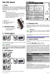
5.2 Digital outputs (Y)<br />
Digital outputs (<strong>SP9</strong> output signals) are connected to the output terminals where the<br />
terminal C1-C4 is common for outputs Y1 to Y4 and the terminal C5-C8 is common<br />
for Y5 to Y8. The figure shows an example of the external and internal wiring<br />
circuits of output Y1 (the same for all digital outputs). Y2 output switches negative<br />
branch power relay coil and vice versa Re2 Y6 output switching power supply<br />
positive branch of the relay coil Re6 (voltage relay must correspond to an external<br />
source voltage!). The polarity of the terminals C1-C4 and C5-C8 terminals is<br />
irrelevant - can be plus or minus.<br />
5.3 Analog Input (<strong>SP9</strong>-A and <strong>SP9</strong>-T only)<br />
<strong>SP9</strong>-A and <strong>SP9</strong>-T versions have 1 analog input, which is connected to the input<br />
terminals (A1+, A1-).<br />
<strong>SP9</strong>-A - Analog input is designed to measure the current 0-20 mA. The measured<br />
value 0-20 mA can be converted to user units. For example the measured current<br />
from 4 to 20 mA can be displayed as the pressure of 0-5 MPa (see the chapter<br />
Configuration - program SP Init).<br />
<strong>SP9</strong>-T - Analog input is designed to measure the temperature -50°C …+150°C<br />
(using KTY 81-210 temperature sensor)<br />
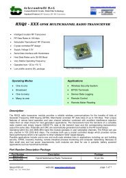
5.4 Front Panel<br />
1 2<br />
3 4<br />
5 6<br />
7 8<br />
IN(X)<br />
PWR<br />
<strong>GSM</strong><br />
ERR<br />
OUT(Y)<br />
1 2<br />
3 4<br />
5 6<br />
External<br />
power supply<br />
8 to 30 V DC<br />
+<br />
C1-C4 Y2 Y4 Y5 Y7 Y8<br />
Y1 Y3 C5-C8 Y6 - +<br />
+<br />
+<br />
Re2<br />
+<br />
Re6<br />
8-30V<br />
DC<br />
Výstupy<br />
Internal wiring<br />
of input X1<br />
Power supply of<br />
<strong>SP9</strong> 8 to 30 V DC<br />
Internal wiring<br />
of output Y1<br />
The front panel of the <strong>SP9</strong> includes <strong>SP9</strong> status LEDs and inputs and<br />
outputs status LEDs. The state is only shown for inputs X1 to X8 and all<br />
outputs Y1 to Y8 (LED for Y7 and Y8 are located above the USB connector).<br />
Under the removable cover is placed SIM card reader, the button<br />
(intended for future use) and a connector for connecting of expansion<br />
board (<strong>GSM</strong>-SP-CB2 or <strong>GSM</strong>-SP-CB5) or unit (<strong>GSM</strong>-SP-EXP).<br />
SIM card is inserted into the reader (cut corner down) and contacts to<br />
center of <strong>SP9</strong>. Proper insertion can be identified by a mechanical click. SIM<br />
card can be removed by pressing gently on it (until a click) and release.<br />
Then the SIM card can be pulled out.<br />
USB connector for PC connection is hidden under the square cover.<br />
Meaning<br />
LED COLOR Dark Light Blink 1x<br />
per 3sec<br />
Power ON<br />
PWR green Power OFF or battery - -<br />
powered<br />
<strong>GSM</strong><br />
ERR<br />
1 to 8<br />
(IN)<br />
1 to 8<br />
(OUT)<br />
blue<br />
red<br />
green<br />
green<br />
no<br />
signal<br />
<strong>SP9</strong> OK:<br />
normal<br />
operation<br />
<strong>GSM</strong><br />
input not<br />
activated<br />
output not<br />
activated<br />
other<br />
<strong>GSM</strong> error<br />
<strong>GSM</strong> OK:<br />
normal<br />
operation<br />
1k<br />
<strong>SP9</strong><br />
3k9<br />
<strong>SP9</strong><br />
0,2A<br />
X1<br />
Inputs<br />
COM<br />
Y1<br />
C1-C4<br />
Blink<br />
Fast 1:1<br />
SIM<br />
problem<br />
Error Error Error<br />
input is<br />
activated<br />
output is<br />
activated<br />
-<br />
- -<br />
card<br />
during<br />
transition time<br />
before input<br />
status is<br />
accepted after<br />
input change<br />
(before SMS<br />
can be sent)<br />
6. Remote Control<br />
6.1 SMS Message control<br />
<strong>SP9</strong> is controlled via SMS messages of <strong>GSM</strong> network. Command SMS messages are<br />
in form:<br />
[]<br />
Example:<br />
1234 STATE … <strong>SP9</strong> returns an SMS containing status<br />
1234 DOUT1 ON … <strong>SP9</strong> output1 will be switched on. Confirmation SMS will be<br />
returned<br />
1234 DOUT8 PULSE NOBACK … <strong>SP9</strong> pulse on output8 will be generated, no<br />
confirmation message will be sent back<br />
It’s possible to write more commands into one command SMS. For higher readability<br />
separate commands by semicolon “;” inside command use “=”.<br />
1234 OUTPUT0=ON; OUTPUT1=ON; OUTPUT3=PULSE;<br />
Names of inputs and outputs are user definable by SPInit program. Command SMS<br />
may look like this:<br />
1234 GATE=OPEN; HEATING=ON; LAMP=BLINK<br />
6.2 Status SMS Text Message<br />
Whenever command SMS contains valid password, <strong>SP9</strong> always returns status SMS.<br />
Status SMS contains following information:<br />
: = = ...<br />
=<br />
= ... <br />
Status SMS message contains information only about selected inputs and outputs.<br />
Selection is done in configuration program SPInit by checking the appropriate<br />
checkbox.<br />
<strong>SP9</strong> Status SMS<br />
Explanation<br />
Example<br />
Device <strong>SP9</strong>:<br />
Device Name (user configurable)<br />
DIn1=on<br />
Digital Input 1 is on<br />
DIn2=off<br />
Digital Input 2 is off<br />
DOut3=on<br />
Digital Output 3 is on (closed)<br />
Signal=58% <strong>GSM</strong> Signal level in %<br />
7. Configuration<br />
For configuration of <strong>SP9</strong> is used special program call SP Init. This program can be<br />
downloaded free of charge from the website ......... www.seapraha.cz <strong>GSM</strong>-<strong>SP9</strong>.<br />
Program SP Init enables:<br />
<br />
<br />
<br />
<br />
Local configuration of <strong>SP9</strong> from PC via USB cable<br />
Local monitoring of <strong>SP9</strong> from PC via USB cable<br />
Remote configuration of <strong>SP9</strong> from PC via <strong>GSM</strong> network (CSD)<br />
Remote monitoring of <strong>SP9</strong> from PC via <strong>GSM</strong> network (CSD)<br />
Note: No USB driver is needed because<br />
<strong>SP9</strong> is a HID device type. See Windows the<br />
Control Panel System Hardware Device<br />
Manager Human Interface Devices - if<br />
necessary.<br />
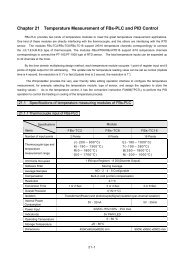
After installation (during the first run) of the<br />
configuration program SP Init it is necessary<br />
to select the device variant (<strong>SP9</strong>-A, <strong>SP9</strong>-D,<br />
<strong>SP9</strong>-T).Select expansion unit <strong>SP9</strong>EXP (if connected) or “No extension”.<br />
After connecting the USB cable to <strong>SP9</strong> the proper COM port is selected automatically<br />
(<strong>SP9</strong> has to be powered!). After pressing the [Connect] <strong>SP9</strong> establishes<br />
communication with the PC (see the "Connection: Connected"). Now it is possible to<br />
read, change and write configuration to <strong>SP9</strong> or read it or write to a file on PC.<br />
7.1 SPInit - Tab “General”<br />
In the "General" tab you can set up the PIN for the SIM card, station name, event<br />
after turning on the device and internal inputs.<br />
<strong>GSM</strong>-<strong>SP9</strong>_<strong>Users</strong>_Manual_EN_v1-14.docx / 2013-04-26 page #2 of 6