26114745-GSM-SP9_Users_M... .pdf
26114745-GSM-SP9_Users_M... .pdf
26114745-GSM-SP9_Users_M... .pdf

You also want an ePaper? Increase the reach of your titles
YUMPU automatically turns print PDFs into web optimized ePapers that Google loves.
7.9 SPInit - Important Terms Explanation<br />
PIN (Personal Identification Number – usually four digits number). Only persons<br />
with knowledge of PIN can operate a SIM card (in case the PIN usage on a SIM card<br />
was activated). Usage of the PIN can be deactivated. Insert the SIM card to your<br />
mobile phone and follow the instruction in the mobile phone manual. (Usually the<br />
PIN usage can be deactivated in Menu -> Security -> PIN).<br />
ACCESS CODE = Password for SMS commands, configuration and monitoring of<br />
<strong>SP9</strong> accepts only SMS with a valid access code. The password is requested also for<br />
connection of <strong>SP9</strong> (via USB cable or remotely via data connection of <strong>GSM</strong> network).<br />
Factory setting of access code is “1234”.<br />
EVENT = level change in case of digital input, zone change in case of analog inputs.<br />
<strong>SP9</strong> can react on EVENTS by several ACTIONS if it is setup this way. <strong>SP9</strong> can send<br />
SMS messages on selected phone numbers and/or to make voice calls on selected<br />
phone numbers.<br />
ACTION = one voice call or one SMS to one user. Any EVENT can contain several<br />
ACTIONS.<br />
USER LIST = List of all users and their phone numbers which are used for<br />
ACTIONS. User names are used only for better clarity. <strong>SP9</strong> does not use them in any<br />
way.<br />
DEVICE OFF = Disconnection of <strong>SP9</strong> from any form of power supply (including<br />
internal battery).<br />
Here it is possible to select the format of the values (not for internal inputs), which<br />
used for displaying and the unit values.<br />
Conversion<br />
In this table, you can specify your own conversion of input values to be displayed<br />
(not for internal inputs)<br />
In the tab "Zones and<br />
events" can be set the<br />
name of the zone and the<br />
limit value with hysteresis.<br />
Whenever the actual value<br />
is inside the zone, the zone<br />
name is displayed in the<br />
status SMS message.<br />
Furthermore is possible to<br />
set up the action which will<br />
be executed after the input<br />
level transition (above or<br />
below a certain level) after<br />
a specified delay. Setting of<br />
actions and macros is the<br />
same as for the digital<br />
inputs<br />
DEVICE ON = Connection of <strong>SP9</strong> to any form of power supply. (Processor reset has<br />
the same effect).<br />
POWER ON/OFF = Connection/disconnection of supply terminals from external<br />
power supply. (<strong>SP9</strong> supplied from internal battery can send SMS about Power<br />
recovery and Power outage).<br />
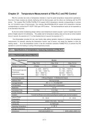
7.10 Remote Configuration<br />
<strong>SP9</strong> can be configured remotely via <strong>GSM</strong><br />
data connection (CSD) in the same way<br />
like via USB cable (Note: You need any<br />
<strong>GSM</strong> modem connected to your PC). Just<br />
click in menu [Options] and in new<br />
window called “Options” set the “Station’s<br />
phone” number for data connection to<br />
<strong>SP9</strong>. Click [OK] to close the window. For<br />
connection select proper COM port which<br />
is used for communication with modem<br />
and press the button [Connection]. Confirm the phone<br />
number [Yes]. When the <strong>GSM</strong> connection is established it’s<br />
possible to operate the <strong>SP9</strong> in the same way like via USB.<br />
Note: Press [Disconnect] when your task is finished.<br />
Example:<br />
Sample configuration with<br />
the analog input values<br />
conversion to user units:<br />
Analog input is configured<br />
as current input 0-20 mA.<br />
Pressure sensor gives 4 mA<br />
at 0 MPa and 20 mA at 10<br />
MPa (see settings in the<br />
picture).<br />
A/D<br />
Converter<br />
Range<br />
MAX<br />
Zone<br />
HIGH<br />
User<br />
Units<br />
100 kPa<br />
Event SMS<br />
(user defined text)<br />
Increase Over Critical Level!<br />
Decrease on Operational Level.<br />
Status SMS<br />
Name Zone<br />
X<br />
Value<br />
X<br />
PRESSURE HIGH 71kPa<br />
PRESSURE MIDDLE 69kPa<br />
7.11 Events<br />
<strong>SP9</strong> can be set up to inform about events (= changes) on its digital and analog<br />
inputs. <strong>SP9</strong> sends information via SMS message or makes a voice call. By the SPInit<br />
program is possible to set several actions for each event specifying the phone<br />
number – user who will receive an SMS message and who will be called. A various<br />
SMS can be sent to and a voice call can be made to more phone numbers from the<br />
list. The order of SMS and voice calls depends on a list of actions for each action.<br />
Voice call rises the probability the user will not miss received SMS message.<br />
7.11.1 How to create an Event<br />
First of all the Event has to be created in the configuration program SP Init. Click by<br />
a mouse on the symbol of a key . By pushbutton [+ ADD] select requested<br />
action of <strong>SP9</strong> (SMS or voice call), write the text of SMS which has to be sent or<br />
insert the sequence of DTMF numbers in case of a voice call. Now select a user and<br />
add him to a list of users for this event by a click on an arrow [>>]. Please check<br />
carefully the number of<br />
users for an event. In case<br />
the number of users is zero<br />
nothing will happen (no<br />
SMS will be sent).<br />
An event for the analog<br />
input can be created in the<br />
folder Analog inputs. Click<br />
by mouse on the symbol<br />
key . In the "Type and<br />
conversion" can be set:<br />
Input type<br />
Note: Analog input A1 is<br />
current type 0-20 mA (<strong>SP9</strong>-<br />
A) or temperature (<strong>SP9</strong>-T)<br />
and cannot be changed.<br />
User units<br />
Input<br />
Value<br />
MIN<br />
7.11.2 Macros<br />
Macros are useful when you need to get values or input and output states in event<br />
or status SMS messages.<br />
Macro Meaning Example<br />
[DINx NAME] Digital input name Input1<br />
[DINx VALUE] Digital input state On<br />
[DOUTx NAME] Digital output name Output1<br />
[DOUTx VALUE] Digital output state Off<br />
[AIN1 NAME] Analog input name Pressure<br />
[AIN1 VALUE] Analog input value 20<br />
[AIN1 STATE] Analog input zone Low<br />
[BAT] Battery charge level in % 75%<br />
[SIGNAL] <strong>GSM</strong> signal level in % 68%<br />
[STATION] Station name <strong>SP9</strong><br />
Use the following numbers instead of letter “x”:<br />
1-11 in Dinx ... as the number of digital input<br />
1-8 at DOutx ... as the number of digital output<br />
Example:<br />
MIDDLE<br />
LOW<br />
0 kPa<br />
Increase on Operational Level.<br />
Decrease below Operational Level!<br />
PRESSURE MIDDLE 31kPa<br />
PRESSURE LOW 29kPa<br />
Event SMS prepared in configuration:<br />
Alarm! Details: [DIN1 NAME] = [DIN1 VALUE], [DIN5 NAME] = [DIN5 VALUE],<br />
[AIN1 NAME] = [AIN1 VALUE] / [AIN1 STATE], Battery = [BAT] %, Signal =<br />
[SIGNAL]<br />
An incoming SMS message:<br />
Office: Alarm! Details: Door = open, Safe = Ok, Pressure = 0.2Pa/Low, Battery =<br />
75%, Signal = 68%<br />
<strong>GSM</strong>-<strong>SP9</strong>_<strong>Users</strong>_Manual_EN_v1-14.docx / 2013-04-26 page #5 of 6